Whittle V8

Advert

Whittle V8

Home Forums I/C Engines Whittle V8

Viewing 8 posts - 1 through 8 (of 8 total)
  • Author
    Posts
  • #555338
    Zan
    Participant
      @zan

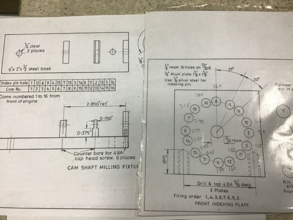
      ce6ce1da-ea52-45b9-8c33-8b3b86819bc0.jpegI’m at the stage of preparing to make the camshaft, but need to make the machining fixture and a travelling steady, Iv had the casting for 20 years…. Here’s the problem

      The photo shows the drawings. Whittle does not fully explain in his notes about the fixture. (Me July 95 #82) The indexing wheel is fixed to the back of the camshaft , his photos of machining it show this at the right on the Miller. However the drawing states only the “ front indexing plate” so is this a view on the END of the fixture OR the view from the Front of the engine/camshaft. I think it’s the former but if I am wrong the engine will run backwards or not at all

      Any guidance from anybody who has actually got the engine running would be much appreciated.


      Edited By Zan on 23/07/2021 12:35:14

      Advert
      #2615
      Zan
      Participant
        @zan

        Camshaft fixture

        #555355
        Ady1
        Participant
          @ady1

          A few threads

          #555363
          Emgee
          Participant
            @emgee

            Zan

            Are you a member of the Whittle V8 engine build group on iO ?

            If not advise you join at the following link, lots of info on that group from people who have completed the build.

            **LINK**

            Emgee

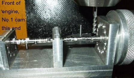
            See note on my picture, cannot confirm this is correct though.

            whittle camshaft machining.jpg

            Edited By Emgee on 23/07/2021 14:19:16

            #555442
            Zan
            Participant
              @zan

              Thanks emgee. Your shaft looks good! Indexing on both ends of the jig?

              I joined the group and asked in there as well but still hoping for an answer in here

              #555449
              Emgee
              Participant
                @emgee

                Zan

                The 3 plates were clamped as one when drilled and reamed to make sure the bearing bores were aligned, all indexing was done at the front as detailed by Eric in the write-up.

                Emgee

                #555502
                Zan
                Participant
                  @zan

                  Emgee

                  So the drawing shows the right end of the jig calling it the front , not the front of the engine which is on the left in your photo with the drawing face outwards on the right, not facing the front of the engine ( actually at the back of the engine!)

                  #555516
                  Emgee
                  Participant
                    @emgee

                    Zan

                    Perhaps someone on the iO group will clarify the details.

                    The reason behind my note on the picture is that the gear driving pin is held in the indexing end and as the gear is at the rear of the engine No.1 cylinder is at the prop end so must be as shown.

                    Emgee

                    Edited By Emgee on 24/07/2021 14:56:44

                  Viewing 8 posts - 1 through 8 (of 8 total)
                  • Please log in to reply to this topic. Registering is free and easy using the links on the menu at the top of this page.

                  Advert

                  Latest Replies

                  Home Forums I/C Engines Topics

                  Viewing 25 topics - 1 through 25 (of 25 total)
                  Viewing 25 topics - 1 through 25 (of 25 total)

                  View full reply list.

                  Advert

                  Newsletter Sign-up