Thompson Engine from Scratch

Advert

Thompson Engine from Scratch

Home Forums I/C Engines Thompson Engine from Scratch

Viewing 25 posts - 1 through 25 (of 29 total)
  • Author
    Posts
  • #2596
    JasonB
    Moderator
      @jasonb
      Advert
      #505504
      JasonB
      Moderator
        @jasonb

        A recent thread on MEM Forum asking about details of the Sissons' Thompson engine got me interested in this one which for some reason had gone under my radar for some time.

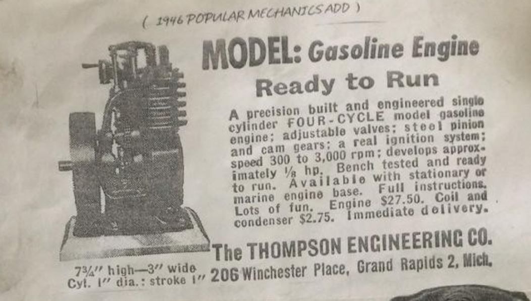
        Originally available from The Thompson Engineering Co of Grand rapids in ready to run form.

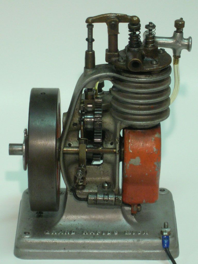
        A casting kit was later available from Sissons that had some differences to the original such as a more angular frame and different head layout

        Although I have visited Bob Herder's site a number of times over the years I had overlooked his version which seems closer to the original

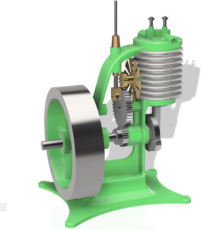
        Rather than take the simple route of locating plans or even a set of castings where someone has done the work for you I opted to design my own from various images found on the net and basic sizes given in the advert. I went for my usual 24mm bore and full metric conversion with stock sizes and metric threads etc. As I'm unlikely to run this in a hull or chassis where some cooling is available I decided to include a cooling fan and also a means to adjust the timing while running, this is the result of a few evenings spent with Alibre showing the main components and general layout.

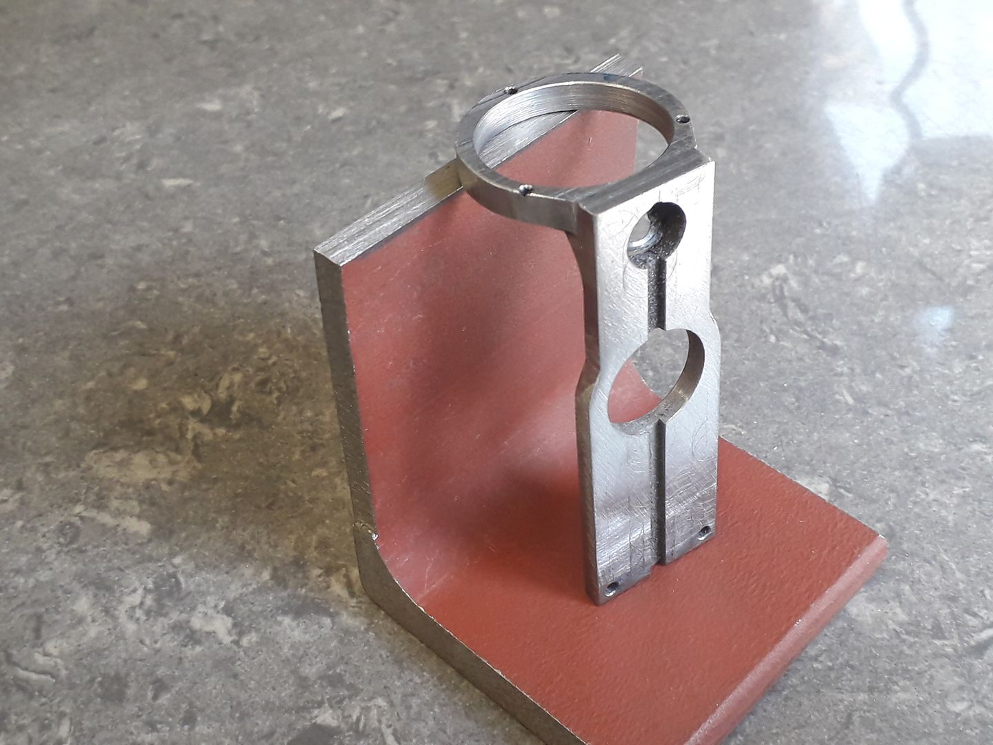
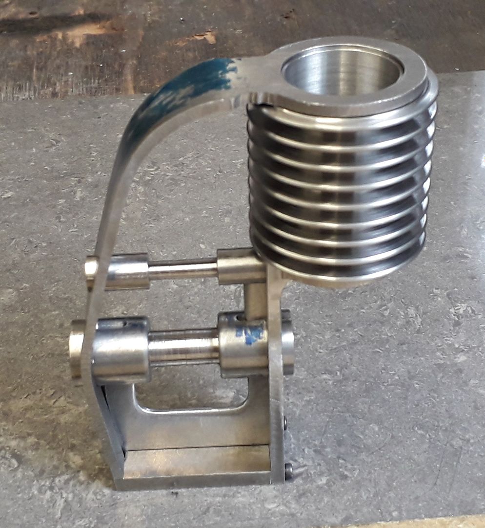
        I made a start on the open frame as this is the main part of the engine and the one requiring the most work. To get a nice solid construction and reduce the number of parts in the single fabrication I used a section cut out of a PFC (parallel flange channel) structural steel to form the vertical leg that carries the boss for crankshaft, camshaft and the bottom of the cylinder. This also had slots milled in for stiffening webs and a couple of holes for screws to keep things together while soldering.

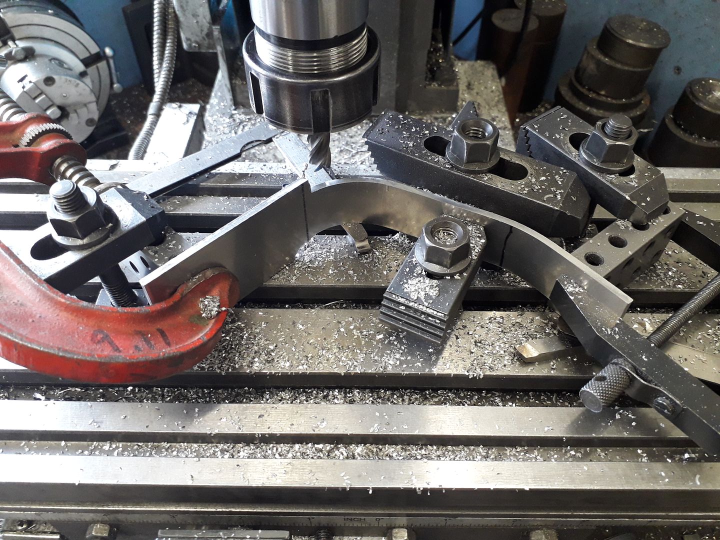
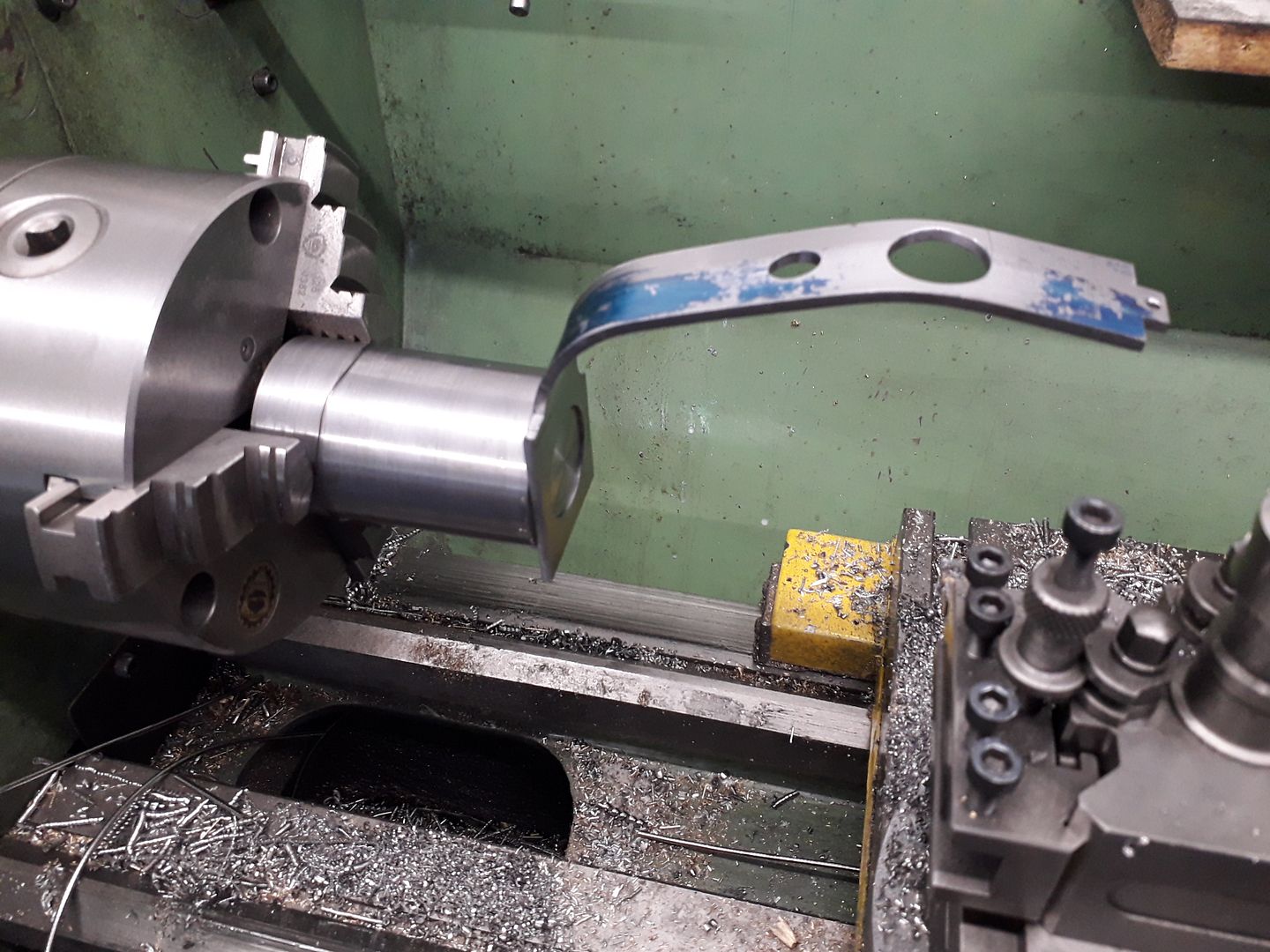
        Next a slightly over width strip was cut from some 3mm steel sheet and that was easily bent to the required shape using a 1:1 drawing as a guide to check that the bends were correct. The bent strip was then clamped to the mill table and most of the excess width milled off down the sides to keep the mass as small as possible so things would heat up quicker when it came to soldering.

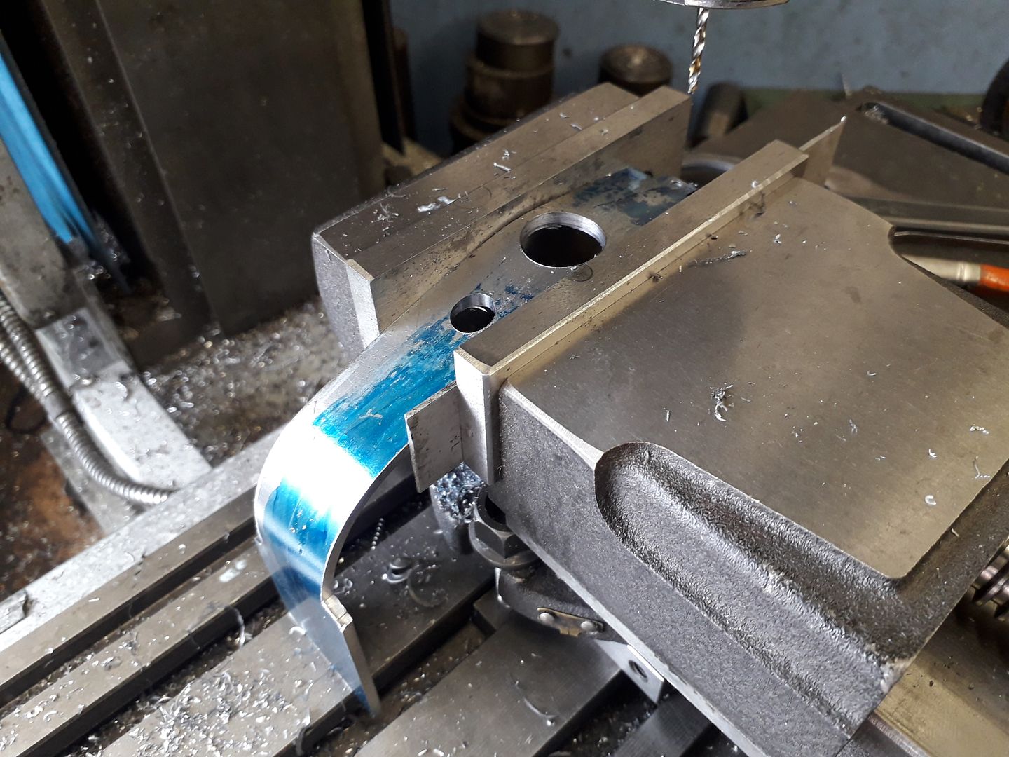
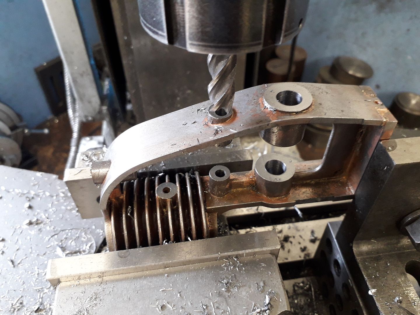
        With the end that will go around the top of the head set vertical to the mill table holes were bored for the various bosses.

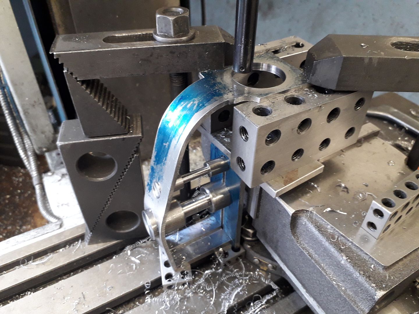
        here you can see the hole being bored that will fit over a spigot on the top of the cylinder, you can also see the bottom plate and bosses in place, again these have had the excess material in the middle turned to a waist so there is less to heat.

        #505531
        Henry Brown
        Participant
          @henrybrown95529

          Jason, I'm not sure if it's just me but there aren't any photo's showing! I looked earlier and assumed it was my slowish internet or ratty old laptop but still the same…

          #505542
          Michael Gilligan
          Participant
            @michaelgilligan61133

            Jason’s [typically astonishing] photos are showing fine this morning.

            MichaelG.

            #505543
            JasonB
            Moderator
              @jasonb

              Thank's Michael, I did my usual copy and paste from my post over on MEM where from comments last night I knew they are showing.

              #505545
              Ramon Wilson
              Participant
                @ramonwilson3

                Yes, I can see them fine too.

                Looks like a typical clever bit of fabrication from the 'Bellamy workshop' to me – you certainly have an eye for breaking the subject down into parts and bringing them together so convincingly Jason – and you do come up with some unusual and different subjects yes

                Are you copying the text in the posting box including images from MEM and just pasting in this one? Never thought to do that before.

                Regards – Ramon

                #505546
                Henry Brown
                Participant
                  @henrybrown95529

                  How strange! I have looked in other threads, notably the workshop progress one, and can see pictures posted by others but not Jason's, and I still can't see them here!

                  There must be something this end, as far as I know nothing has changed other than we have a new 4G router because we have to use mobile internet so I'll check my settings.

                  #505548
                  JasonB
                  Moderator
                    @jasonb

                    Ramon I copy and paste then just have to go through and cut out each link to the images and paste using the image icon here which is quite quick to do.

                    Henry it may be Photobucket is being blocked at your end for some reason as that is what I usually host build thread images on, the odd image in other threads is more likely to be hosted here. Try the MEM thread and see if they come up which will point to Photobucket if they don't.

                    #505556
                    Ramon Wilson
                    Participant
                      @ramonwilson3

                      Thanks Jason – I'll try that on my next project wink

                      Still a bit to do on this one though!

                      #505657
                      Henry Brown
                      Participant
                        @henrybrown95529

                        I checked the MEM thread using Chrome and Edge Jason, no pictures there either so its got to be something my PC doesn't like about Photobucket. I'll have a google and see if I can find a fix, thanks for the suggestion…

                        #506080
                        JasonB
                        Moderator
                          @jasonb

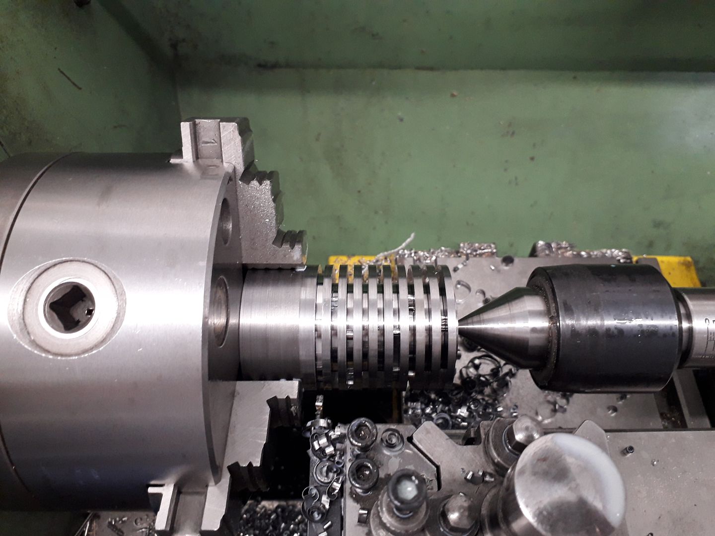
                          When drawing up the engine I played with a few options for the cylinder, I did think of doing an aluminium finned outer with cast iron liner but it would not have been easy attaching this to the frame and the same problem would have existed if I went with an all cast iron option. In the end I settled on a steel finned outer which could be silver soldered into the frame that would accept a cast iron liner.

                          First job was to saw of a length of EN1A steel with sufficient length to allow it to be held in the 3-jaw while a spigot was turned to locate it in the upper part of the frame, here you can see me using the frame to gauge the fit.

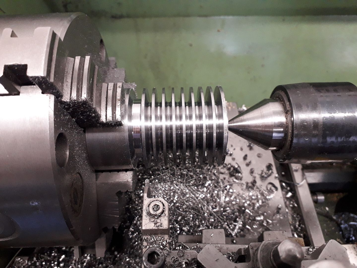
                          Then with some added tailstock support the fins were roughed out using a 2mm GTN type parting insert.

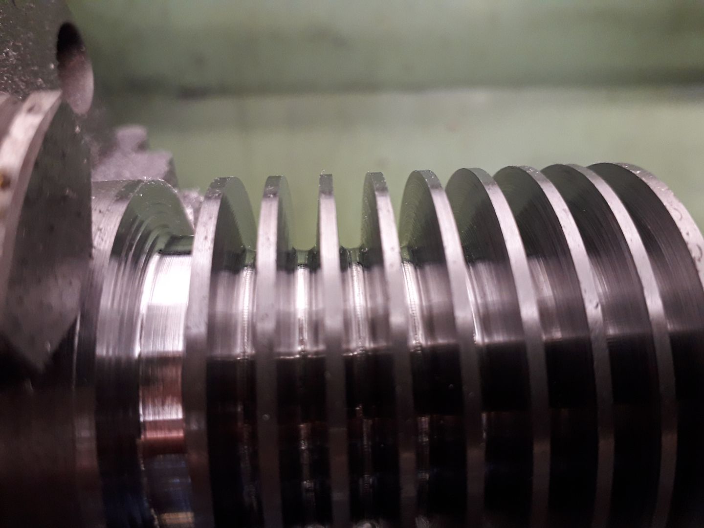
                          Changing to a 2mm dia MRMN tool the sides of the fins were tapered and the valley rounded to give the "cast" look

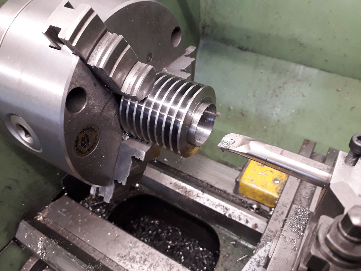
                          The chucking piece was then sawn off and the cylinder outer bored and a spigot cut to locate into the lower part of the frame.

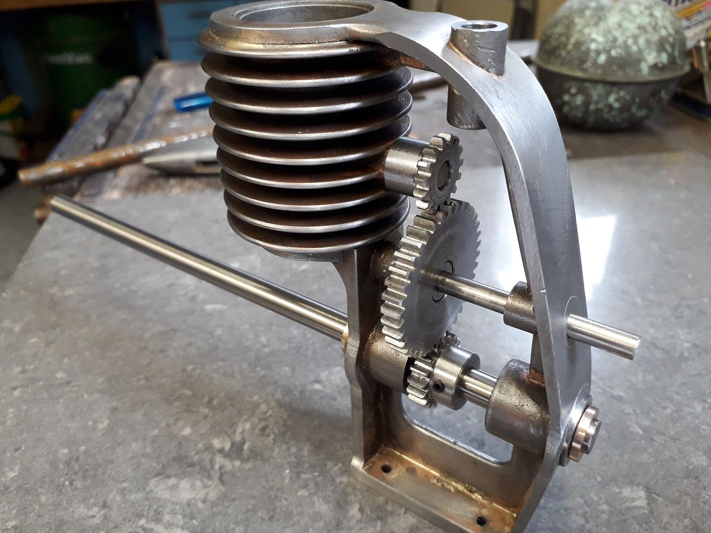
                          The next job was to make the various webs that stiffen the frame, these were located into shallow slots milled into the inner faces of the frame and shaft bosses, here you can see a couple in place, the crests of the fins have also been rounded over.

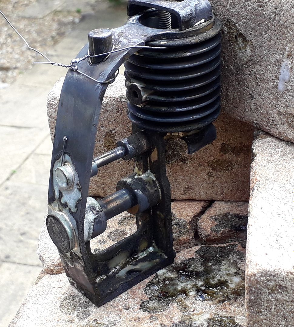
                          After completing the webs and adding more bosses for the valve guide and fan spindle it was time for a bit of silver soldering.

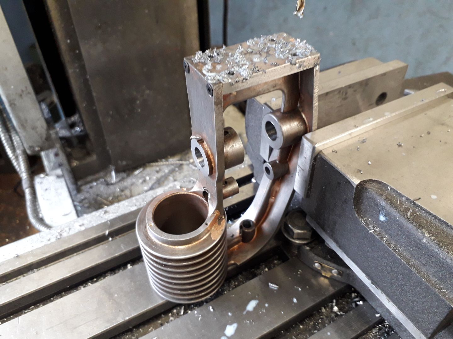
                          I could now treat my fabrication as a casting. After sawing out the spacers between the bosses the inner faces were milled back to length then the frame held flywheel end upwards and the shaft holes drilled and reamed. If you look closely particularly at the cam shaft boss that I tried to hide with the milling cutter you can see that things moved slightly during soldering but that protruding boss is due to be flushed off so won't show.

                          The bottom was given a quick skim and the mounting holes added

                          I opted for off the shelf gears as they are cheap particularly as they were wide enough to cut down the middle so I have some for the next project, some make shift shafts were slipped into the holes and gear mesh checked out OK.

                          #507694
                          JasonB
                          Moderator
                            @jasonb

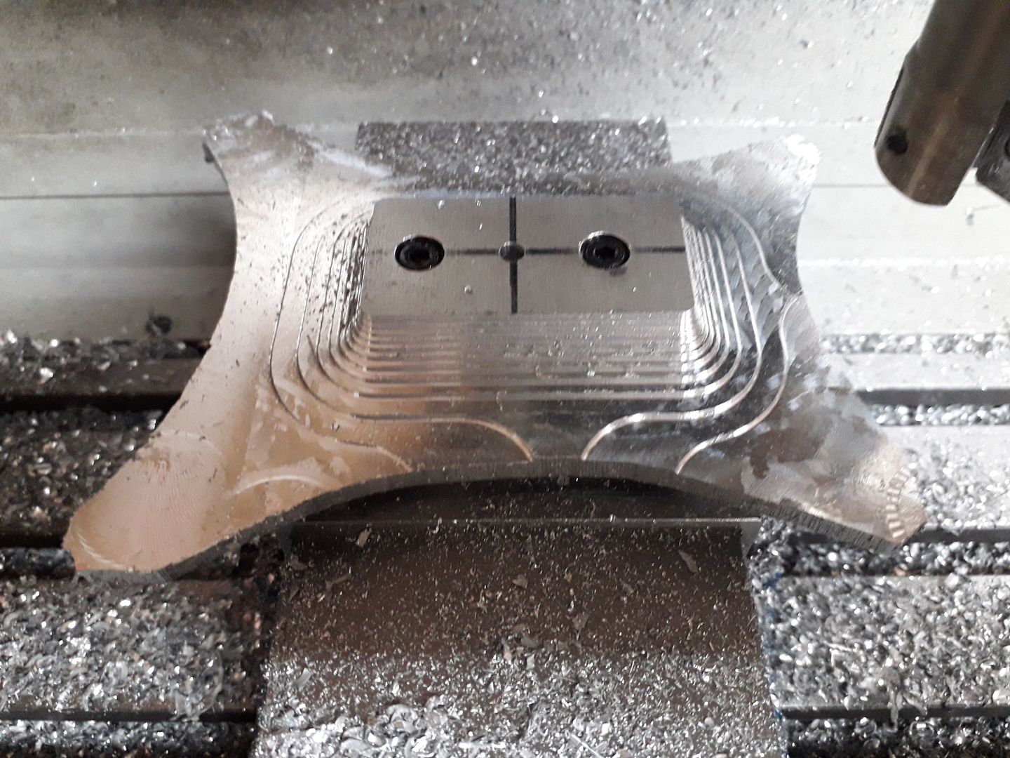
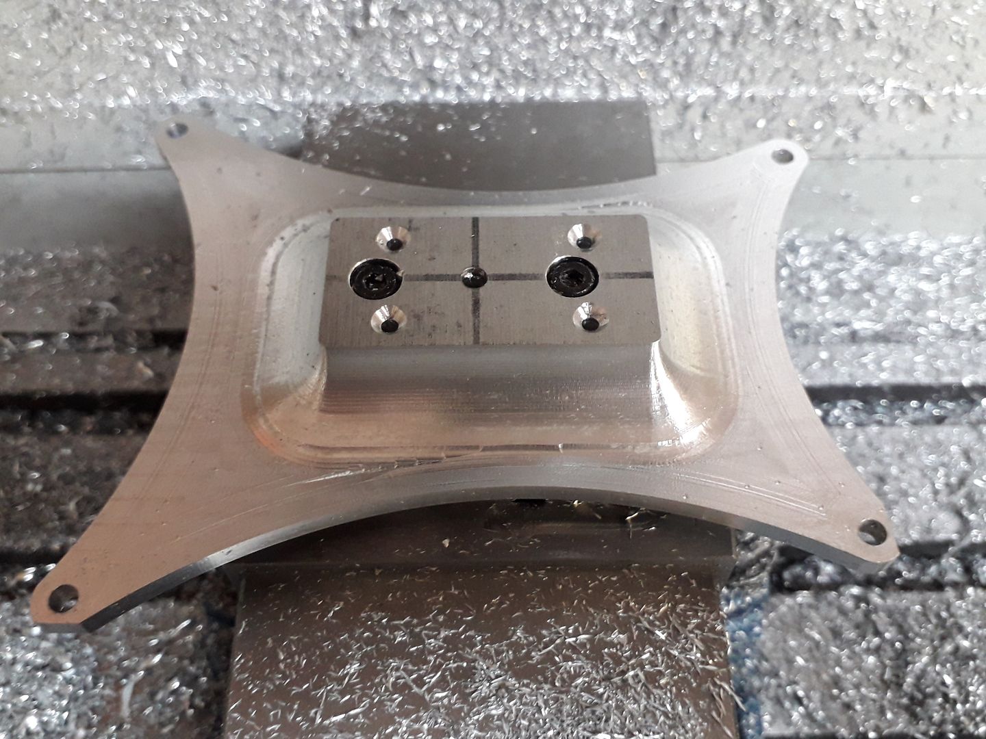
                            I decided to go for a more shapely base than the original as it gave me an excuse to try a few more things out on the CNC. A piece of 16mm 6082 was rough cut to size on the vertical bandsaw and screwed to a block which in turn could be held in the vice. I tried out a 25mm dia 2-flute indexable cutter for the roughing pass which meant a lot less passes around the work due to being able to use a wide 20mm stepover, it worked quite well just getting a bit noisy as I got towards the bottom due to the unsupported edges giving a bit of chatter.

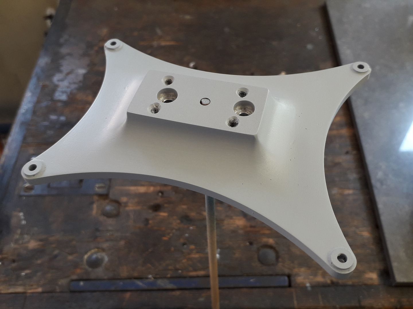
                            The finishing was done with a 6mm 4-flute ball ended cutter using Fusion 360's Steep & Shallow 3D finishing, it did leave a couple of ridges where direction changed due to what I have now found was a slightly too tight Z-axis. You may also be able to spot that I was short of material on a couple of corners, this was due to positioning the work based on the ctr of the top face where the engine fixes but doing the CAM based on the ctr of the stock which was about 2mm different.

                            But with a bit of JBWeld to build up the corners and some work with Emery cloth on the ridges it did not come out too bad once a coat of etch primer had been blown on, I've since rounded over the edges a bit more as they look to crisp in this photo.

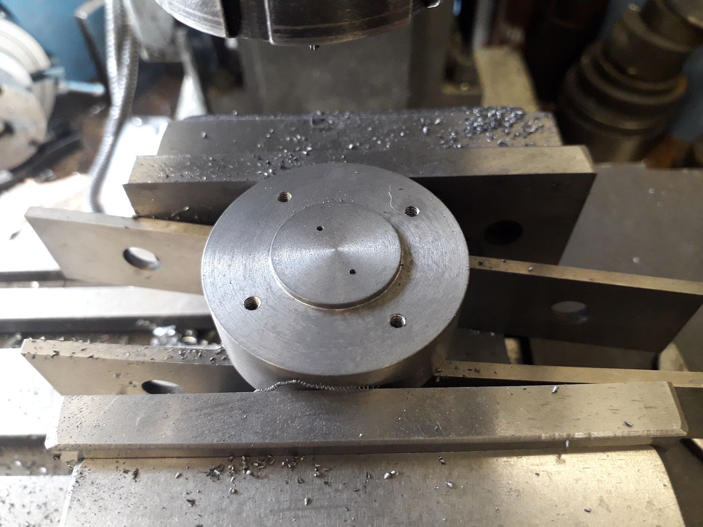
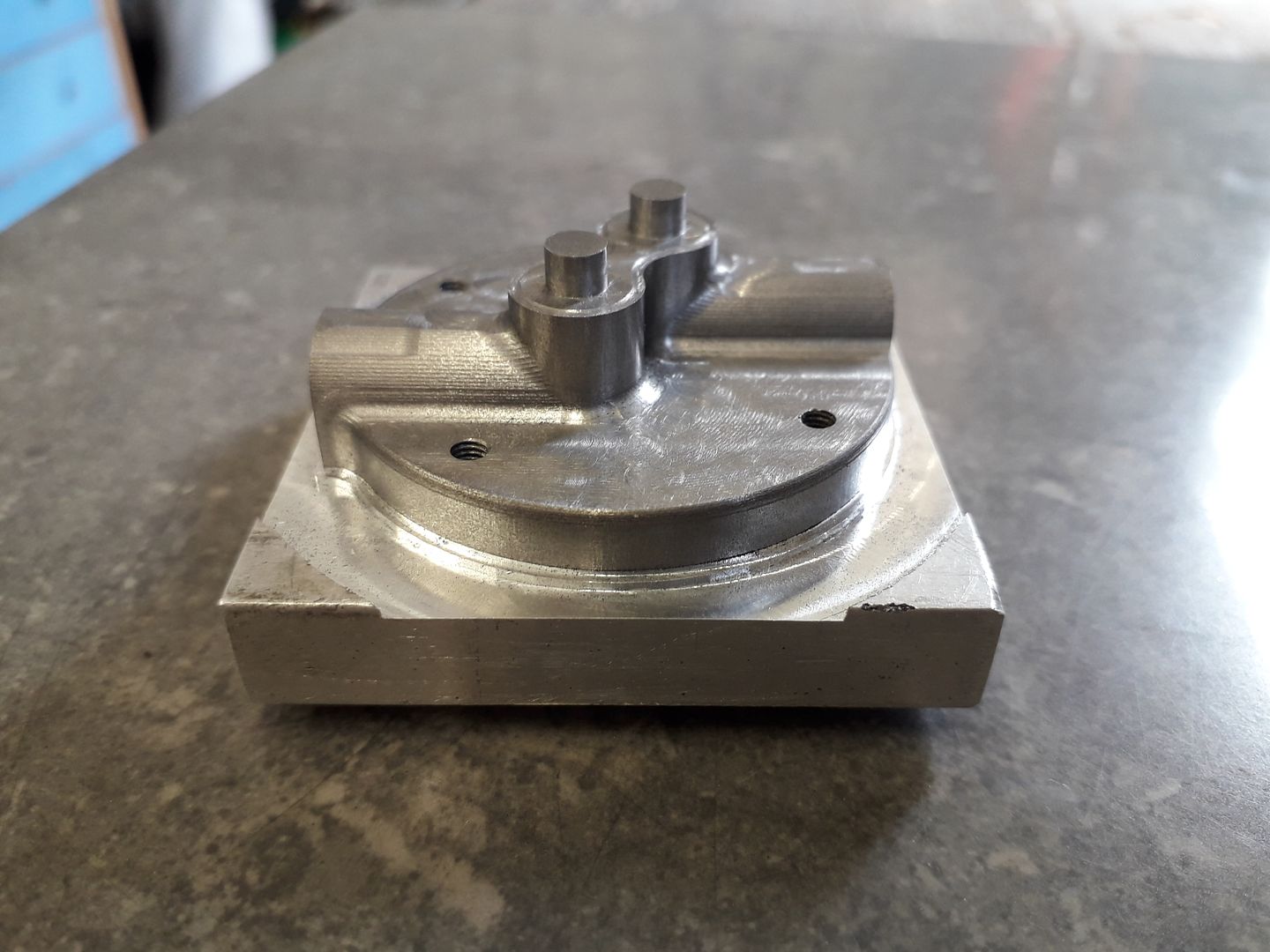
                            The cylinder head started as a lump of cast iron bar in the lathe where a 1mm spigot was turned to locate in the cylinder liner before being transferred to the mill where I drilled and tapped what will become the clearance holes for the head screws and also just spotted the position of the two valve pockets.

                            I was then able to mount the head onto a block of aluminium by screwing up from below which made it easy to hold for shaping the top and edge which was done on the CNC. Still a few ridges left where the mill's head is sticking slightly.

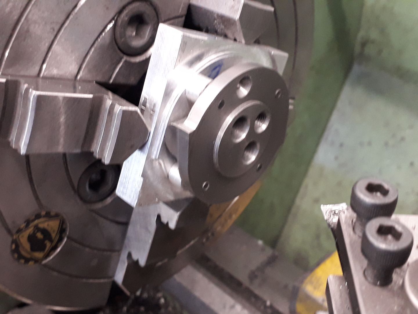
                            Four spacers were turned up so that the head could be held the opposite way round in the 4-jaw and the valve holes drilled, reamed, counterbored and the seats taper turned all in one setting. Then finally back to the lathe to add inlet and exhaust passages which were tapped M6x1 and M8 x 1 respectively.

                            #510702
                            JasonB
                            Moderator
                              @jasonb

                              Continuing to get some use out of the KX3 some of the smaller parts were then made with its aid.

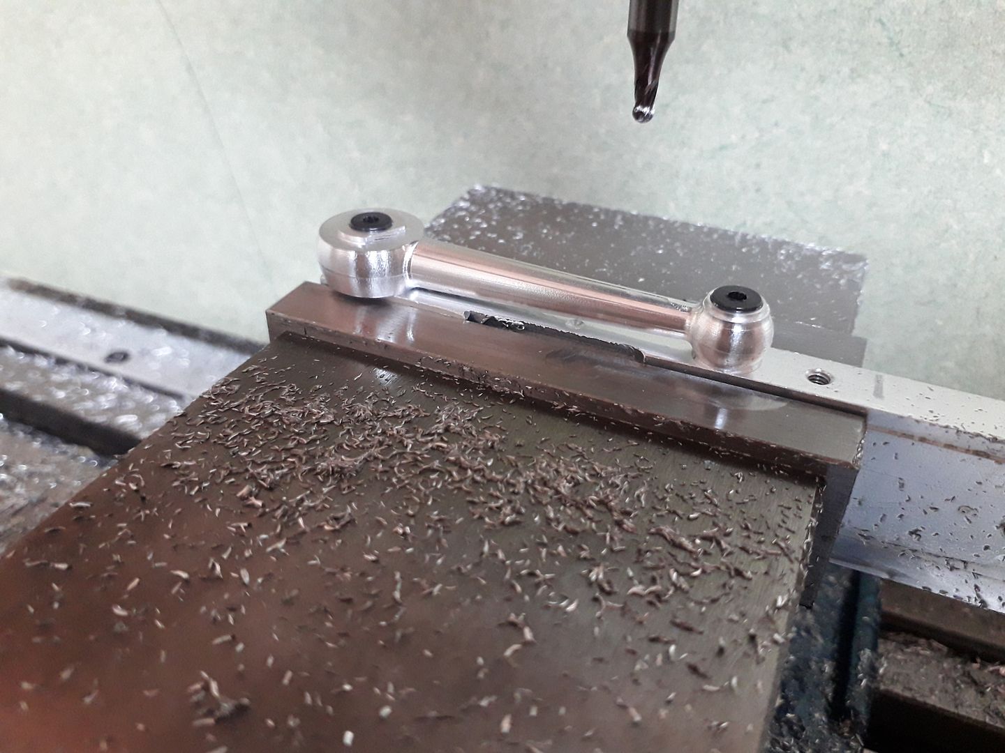
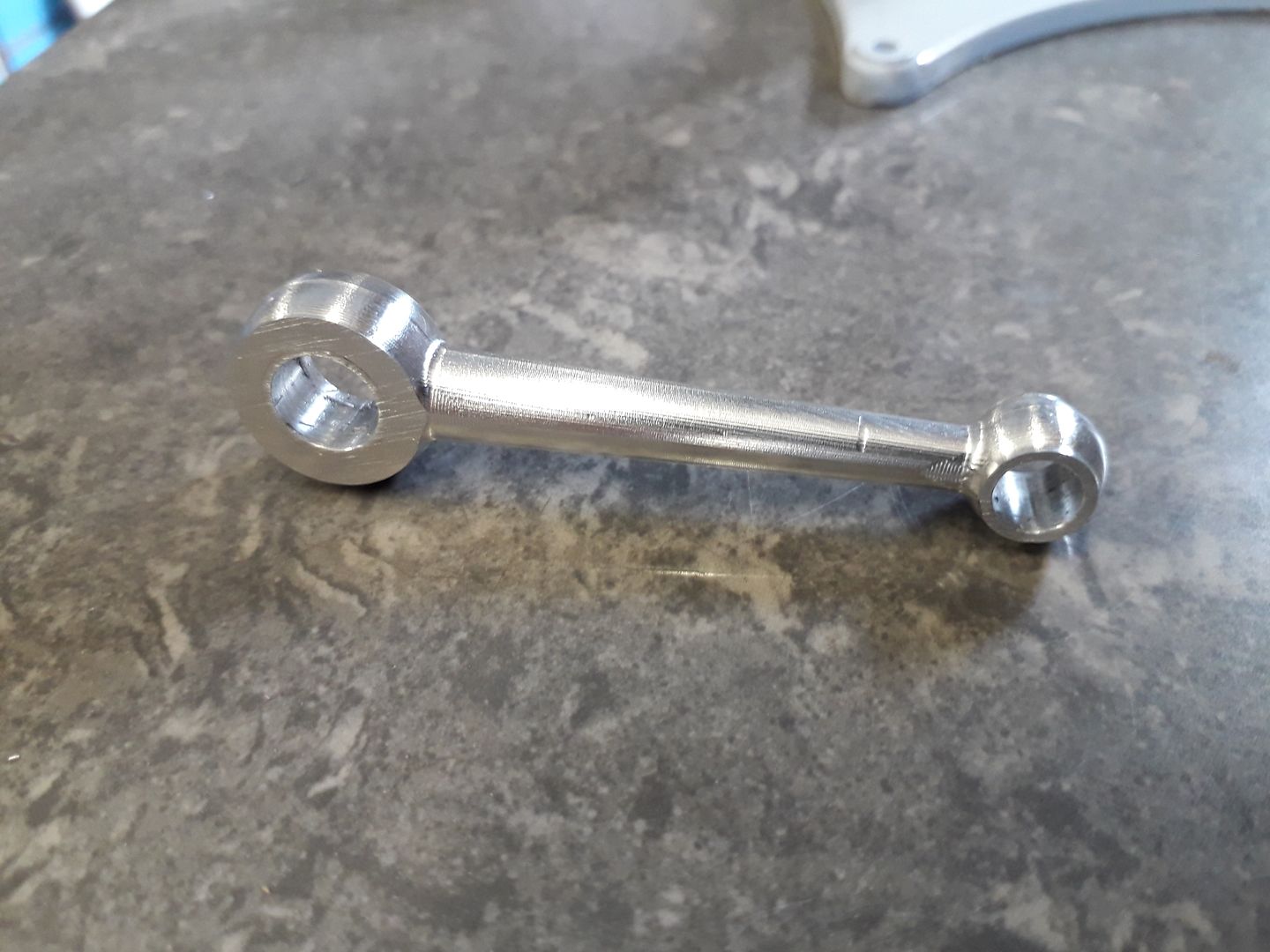
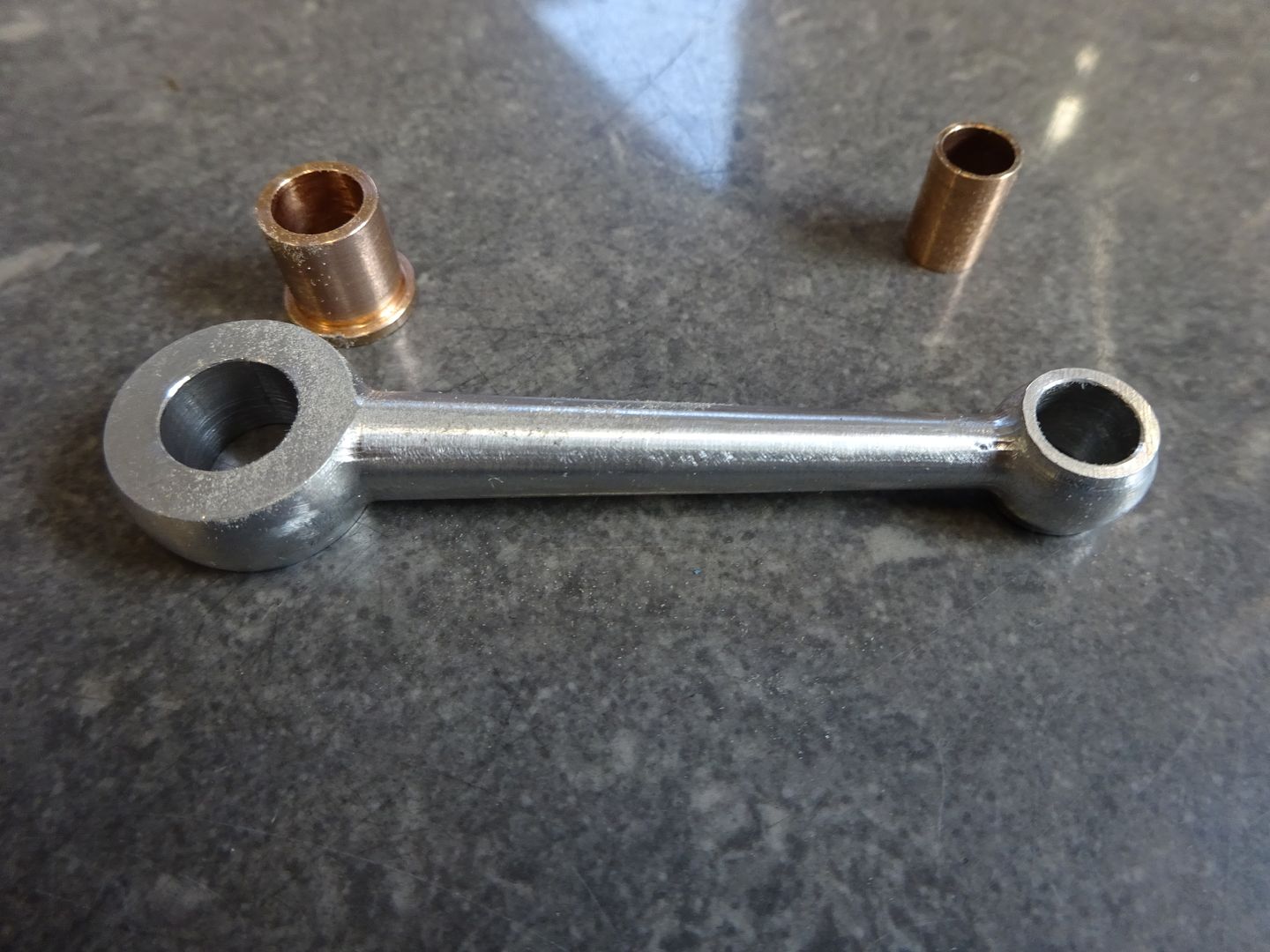
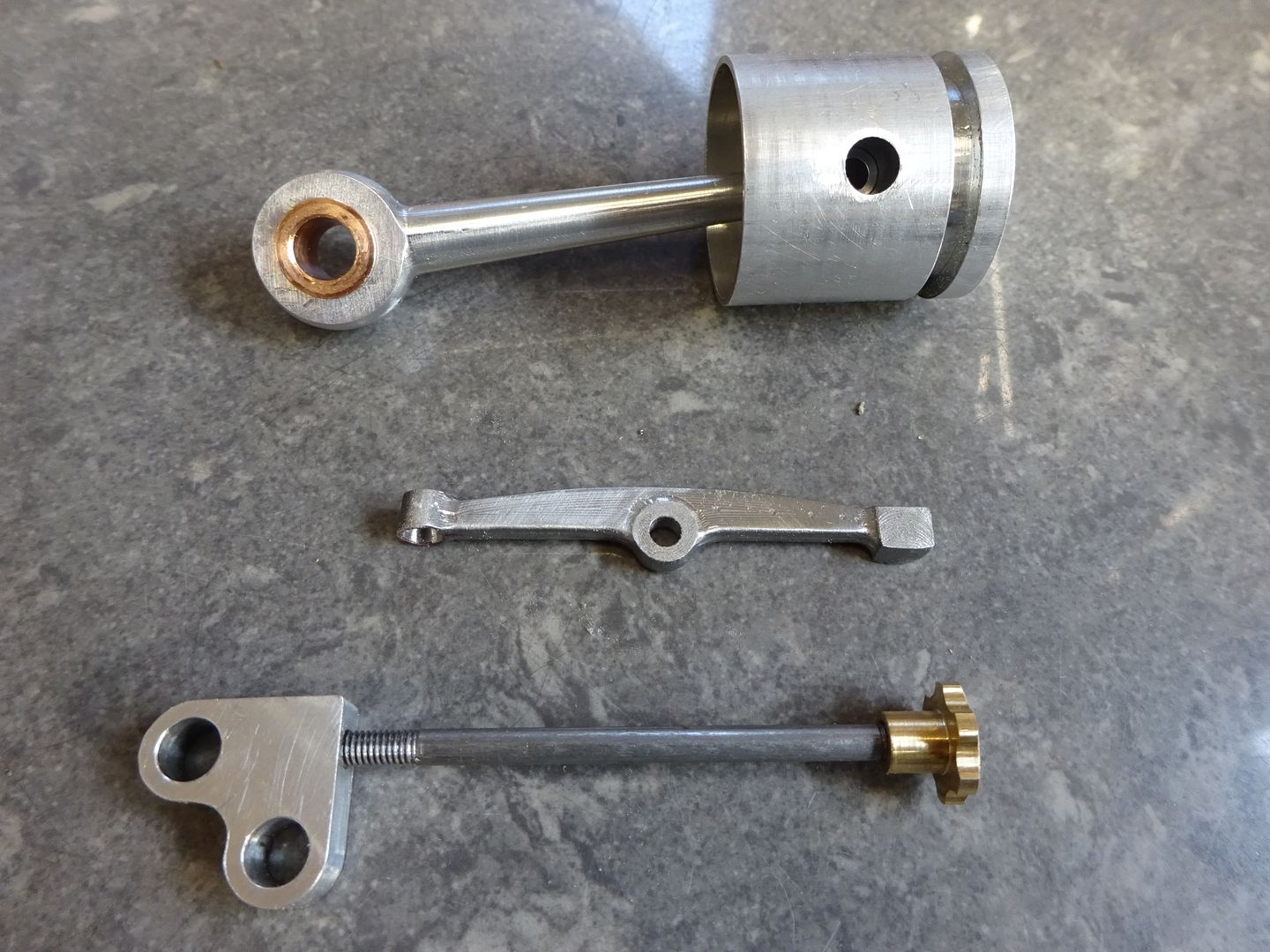
                              For the conrod a piece of round 2014 had flats milled on either and was then drilled and reamed for big and little ends. it was fixed to a holding block with a couple of top hat bushes and given a pleasing shape.

                              Followed by turning a couple of bronze bushes that were a lightly pressed in with a drop of 648 for good measure.

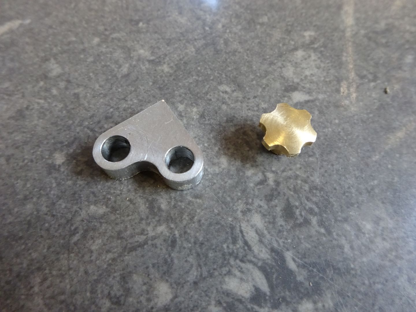
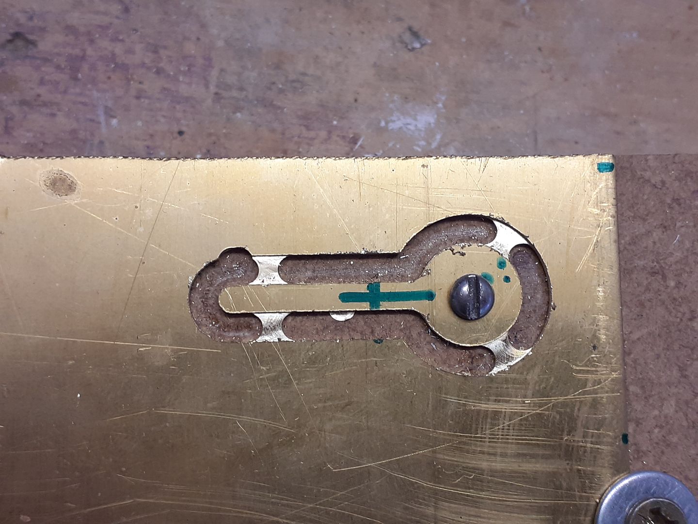
                              Unlike the original I wanted to be able to adjust the ignition timing while the engine was running and the curves on the timing bracket and a small brass knob for the adjuster were again ideal CNC jobs.

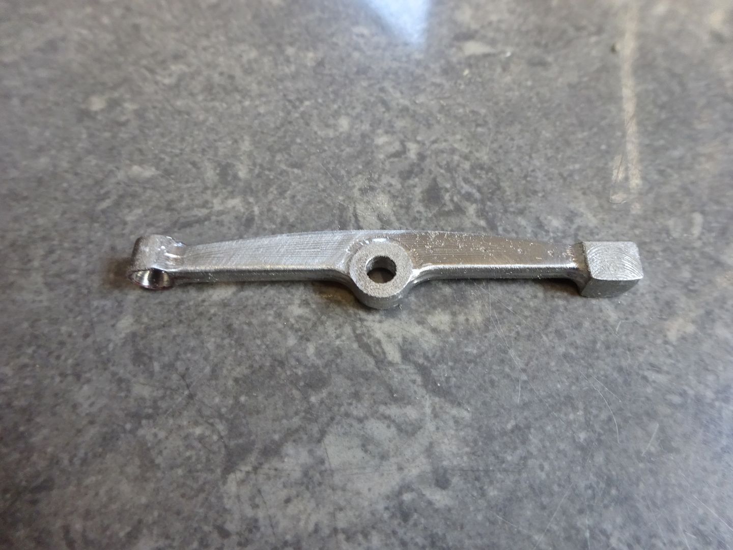
                              The Rocker arm was next up on the list being held at either end on an overlong blank that had the waste material cut off after machining.

                              The piston was a simple turning job but I did use the CNC to mill out the dog bone shaped internal recess, here it is along with the other small parts.

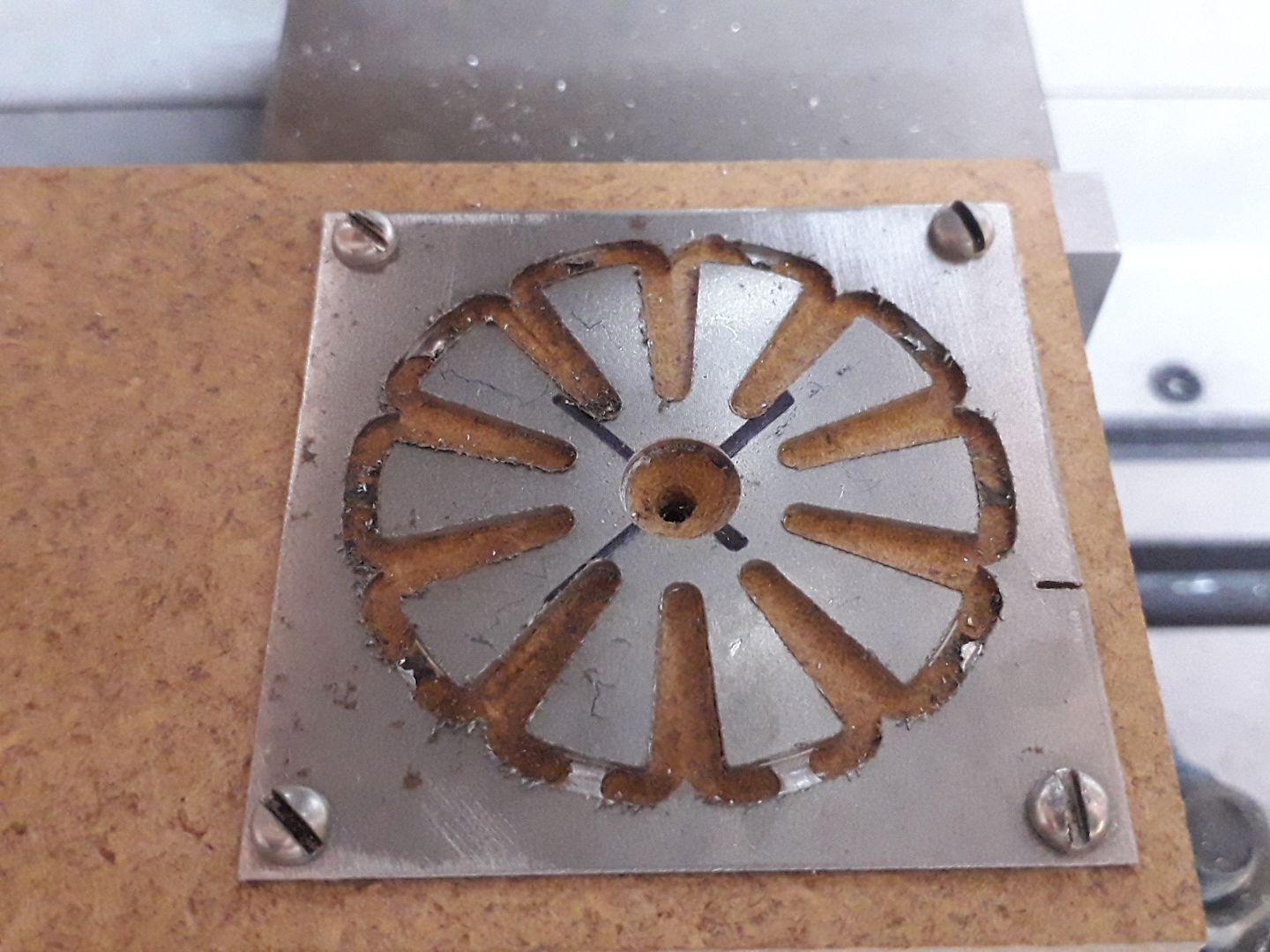
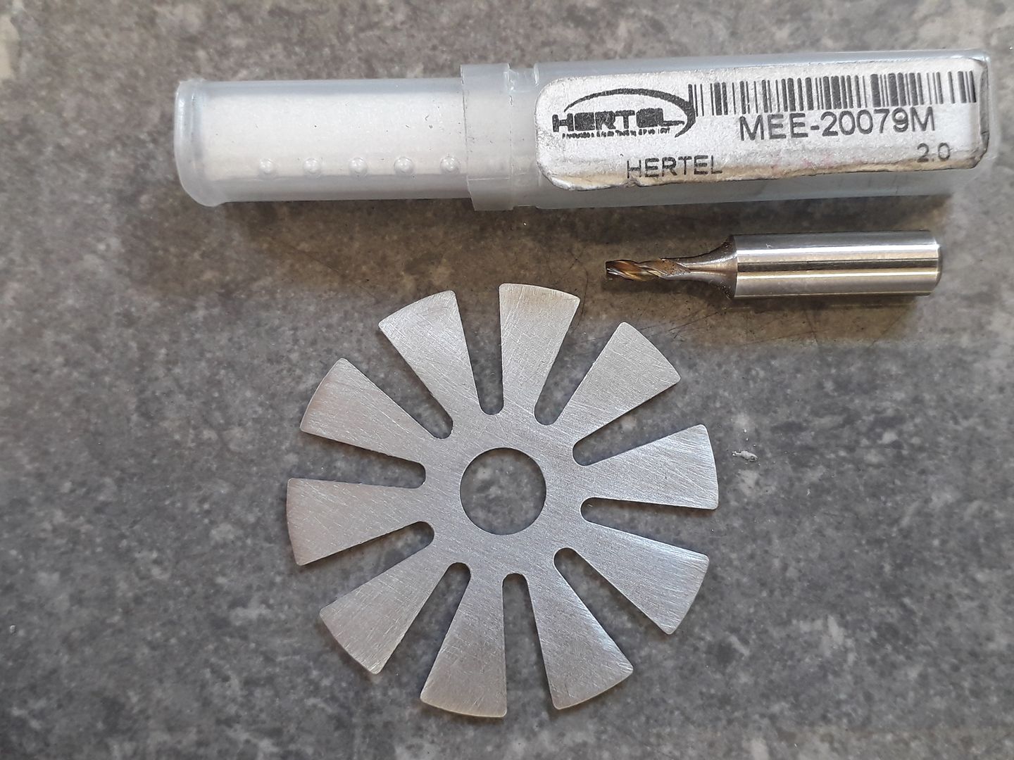
                              Another feature I wanted to add was a small cooling fan which was cut from 0.5mm steel steel, a few tabs were included in the code so that it would remain in place while the 2mm cutter worked it's way around the shape, these were simply cut through and the remains filed off to finish.

                              #513166
                              JasonB
                              Moderator
                                @jasonb

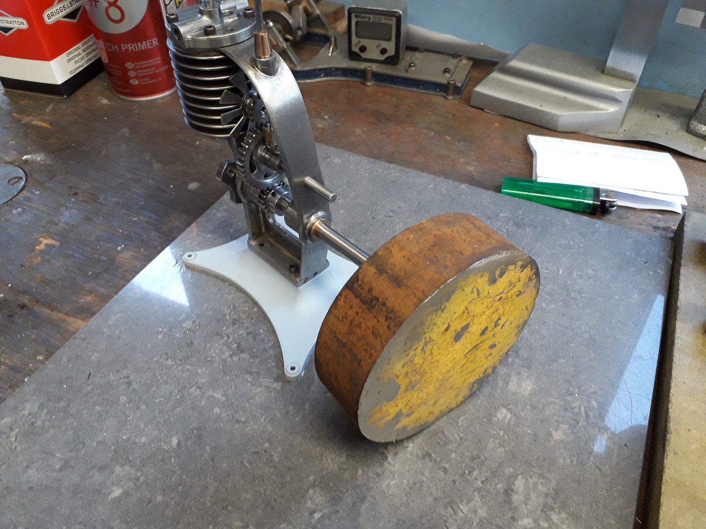
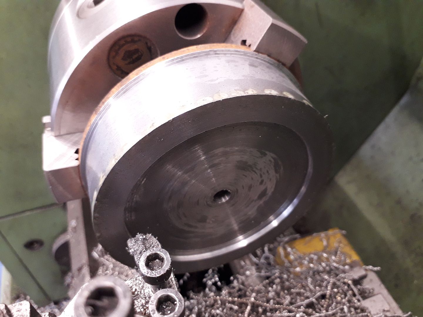
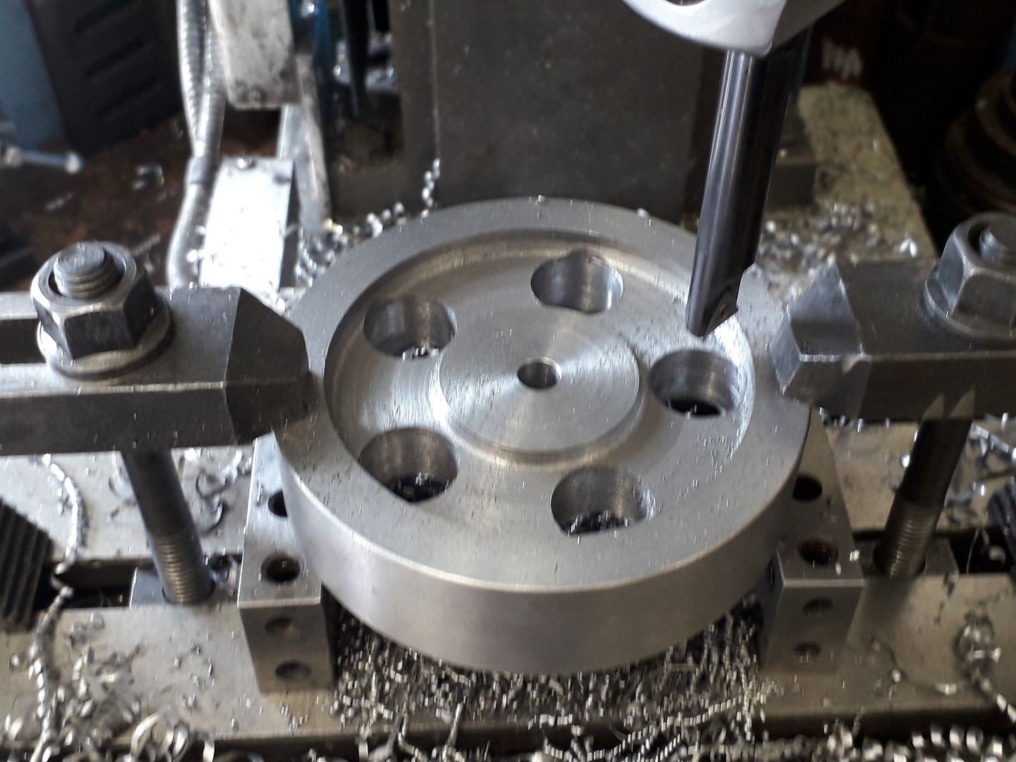
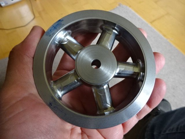
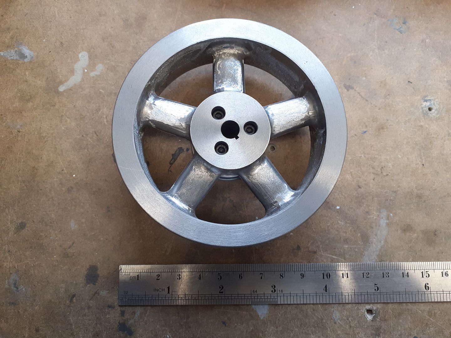
                                I was not too keen on the solid flywheels that are shown in the photos of other engines so decided to go for a spoked one along the lines of what's on the Wall Wizzard with heavy spokes and rim and a large hub that the starter cord pulley could be screwed to. I ordered a piece of EN3 but the colour suggests I got EN8 frown I started buy roughing it down to size on the lathe from the 105mm dia purcheased to 100mm finished dia, I have a couple of holders that allow the two "unused" corners of CCMT inserts to be used and find them ideal for this type of work.

                                The middle section was recessed on both sides to loose some of the waste material and then some holes drilled and bored so that the milling cutter could enter easily and not have so much work to do.

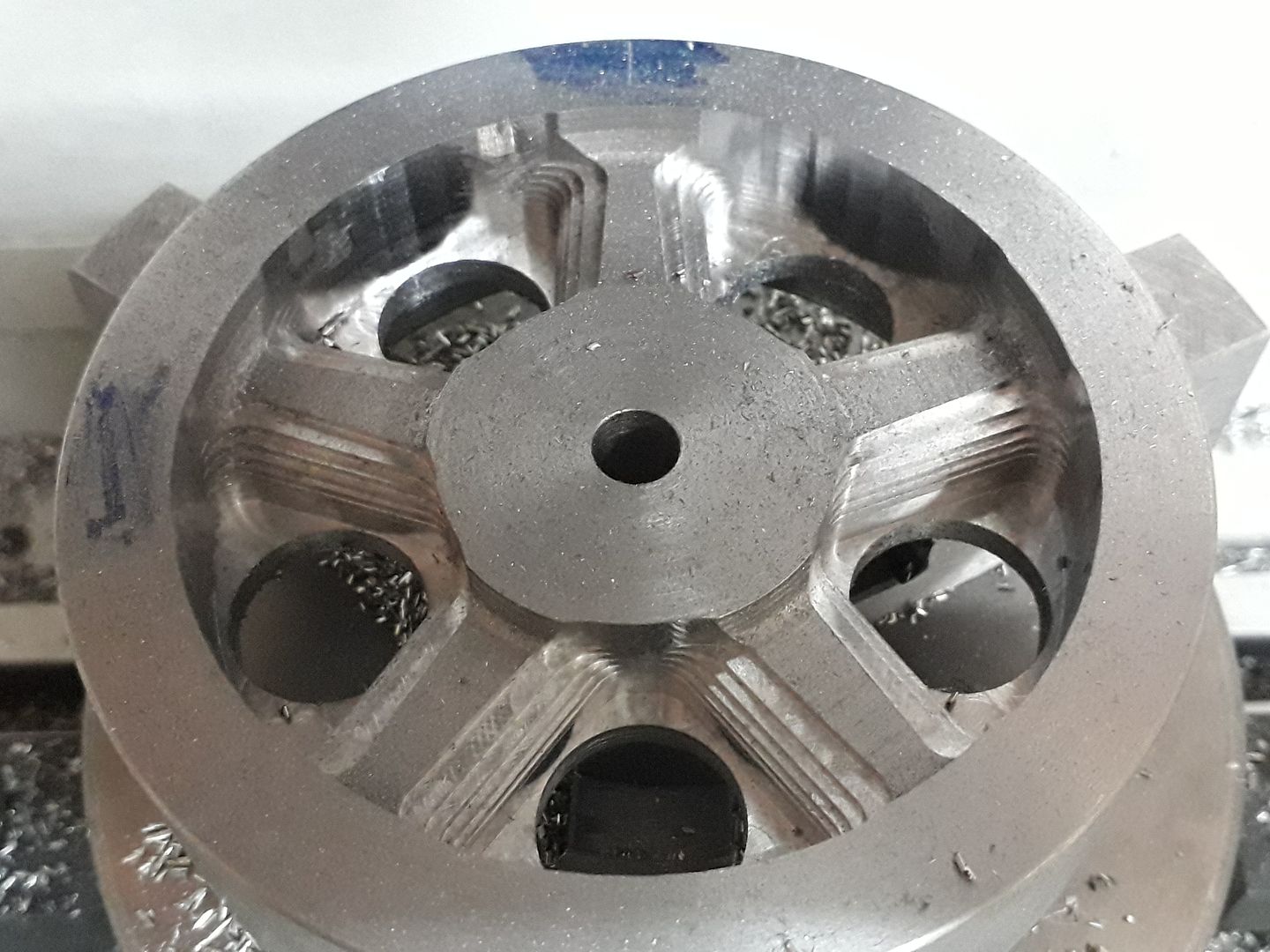
                                With the flywheel held in a 3-jaw chuck mounted to the CNC's table the initial adaptive clearing cut was done leaving the stepped finish below

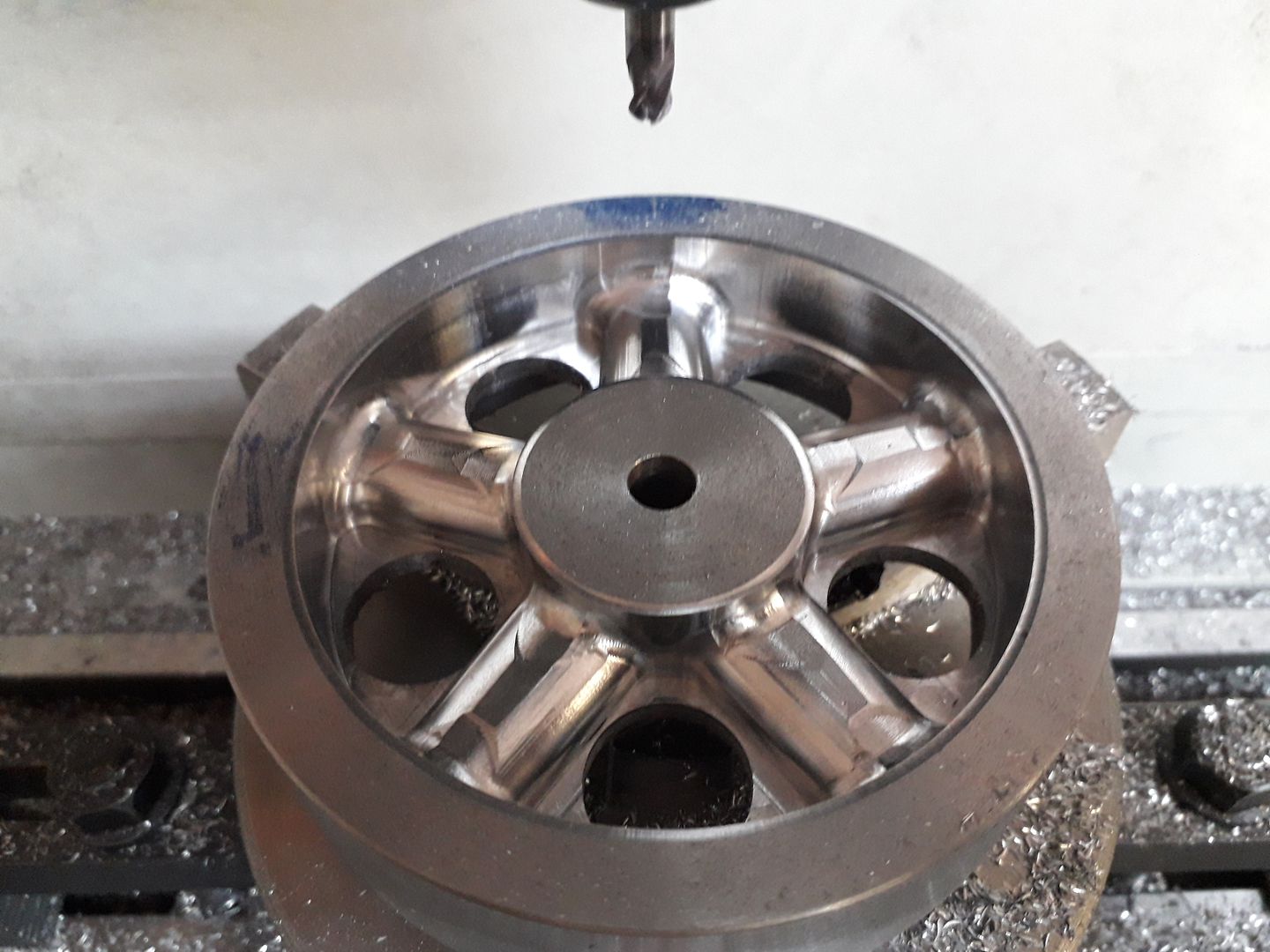
                                A "steep & Shallow" cut was then taken with a 6mm ball ended cutter before flipping the flywheel over and doing the same two operations to the other side

                                There were a few ridges due to some backlash which has now been traced to an overtight head gib strip so the spokes were given a light tickle with the Dremel before adding the pulley screw holes and broaching the keyway.

                                Edited By JasonB on 12/12/2020 19:49:20

                                #513203
                                Ron Laden
                                Participant
                                  @ronladen17547

                                  Morning Jason that turned out well, certainly has a cast look about it and also looks a weighty wheel even at 4 inches, did you choose steel to save all the mess in using iron.

                                  Ron

                                  #513204
                                  JasonB
                                  Moderator
                                    @jasonb

                                    Just easier and cheaper to get hold of the steel, I'm quite happy machining iron and it actually cuts easer so could have done the job quicker.

                                    #514834
                                    JasonB
                                    Moderator
                                      @jasonb

                                      Just a small post tonight. I was not that keen on the fuel tank or carb shown on the earlier engines so I decided to go for something similar to what I made for the Midget not least because I still had five of those miniature jam jars to find a use for!

                                      Apart from having it screw into the cylinder head rather than use a flange mounting the only other real deviation was to have a lever to rotate the throttle barrel rather than using the actual jam jar. The CNC made quick work of this with a 3mm 3-flute cutter blending all the internal and external radii perfectly, I set the CAM to leave a couple of tabs so the part did not fly off part way through cutting and these were easily cay and removed with a needle file.

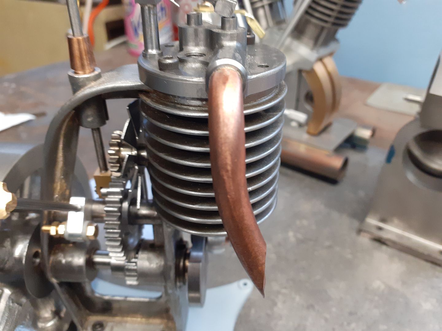
                                      I used a piece of 8mm copper brake line for the exhaust which was filled with lead to stop it collapsing while being bent over a former. The lead melted out without sticking to the uncleaned copper so it was easy to silver solder on a short length of brass drilled 6mm and threaded M8 x 1.0mm so it could be screwed into the head and like the carb locked with a round nut with two spanner flats as I felt that looked a bit nicer than the usual hex nuts.

                                      That just about completes the construction. I have test run the engine but did not bother to video it, these tests did show that it gets quite hot so my hopes to paint it in Kawasaki green have had to be put on hold as I felt some VHT paint may stand a better chance of surviving and their "kermit" green is not as bright sad. Now that the paint has had time to harden I'm waiting for a bright day to take some photos before the paintwork gets mucked up with oil etc doing the video run but hope to have pics and a video for you soon.

                                      #514843
                                      DiogenesII
                                      Participant
                                        @diogenesii

                                        I look forward to that. ..You plan to leave the crank 'open' rather than close it in?

                                        #514844
                                        JasonB
                                        Moderator
                                          @jasonb

                                          Yes I'll be leaving it exposed, adds to the interest if you can see what's going on even if it's a bit messy.

                                          #520745
                                          JasonB
                                          Moderator
                                            @jasonb

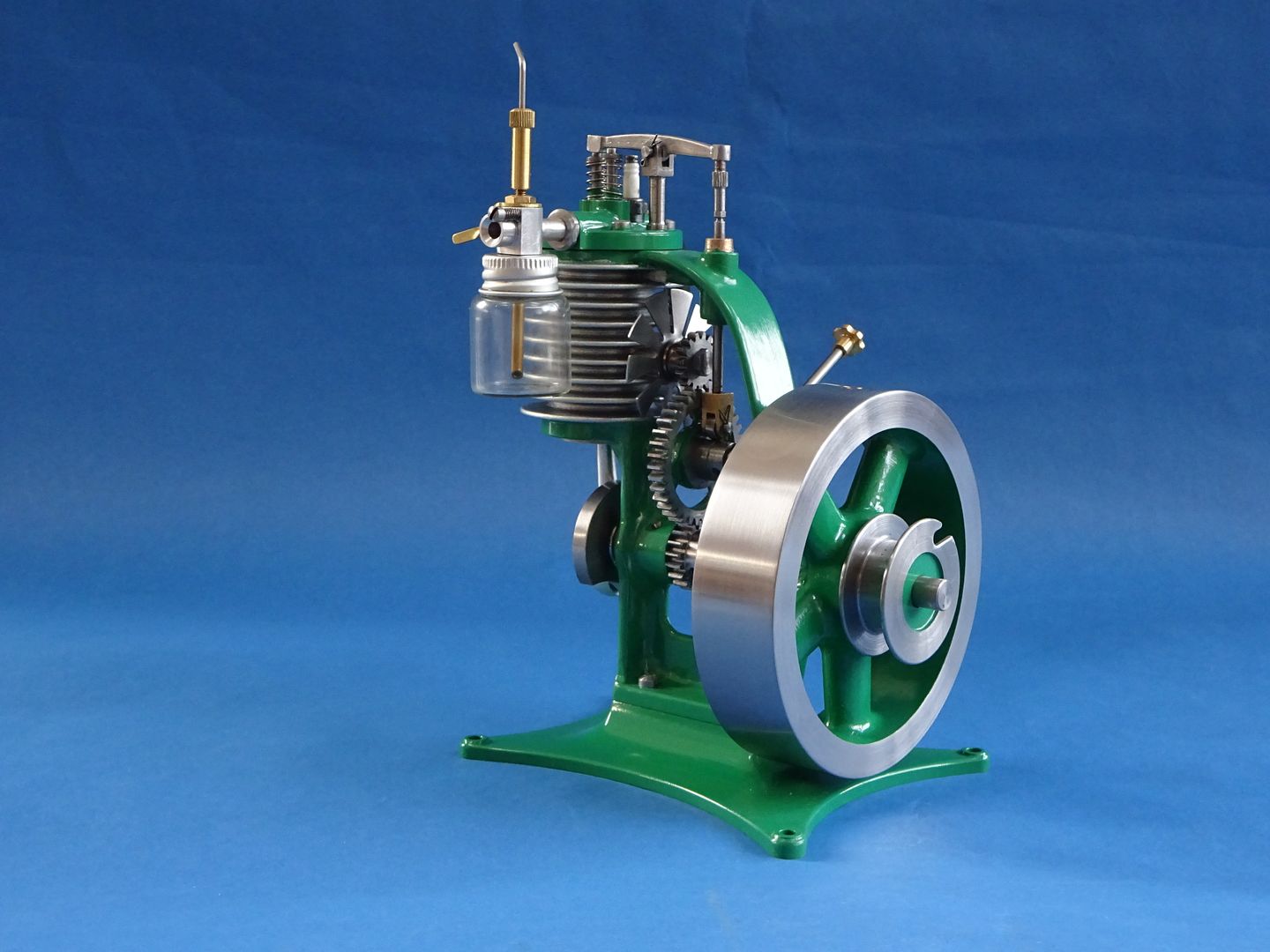
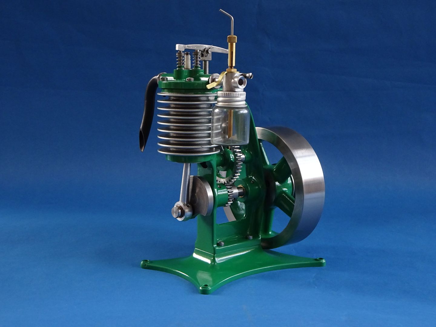
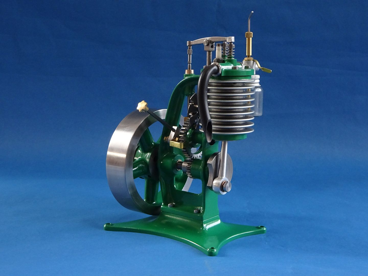
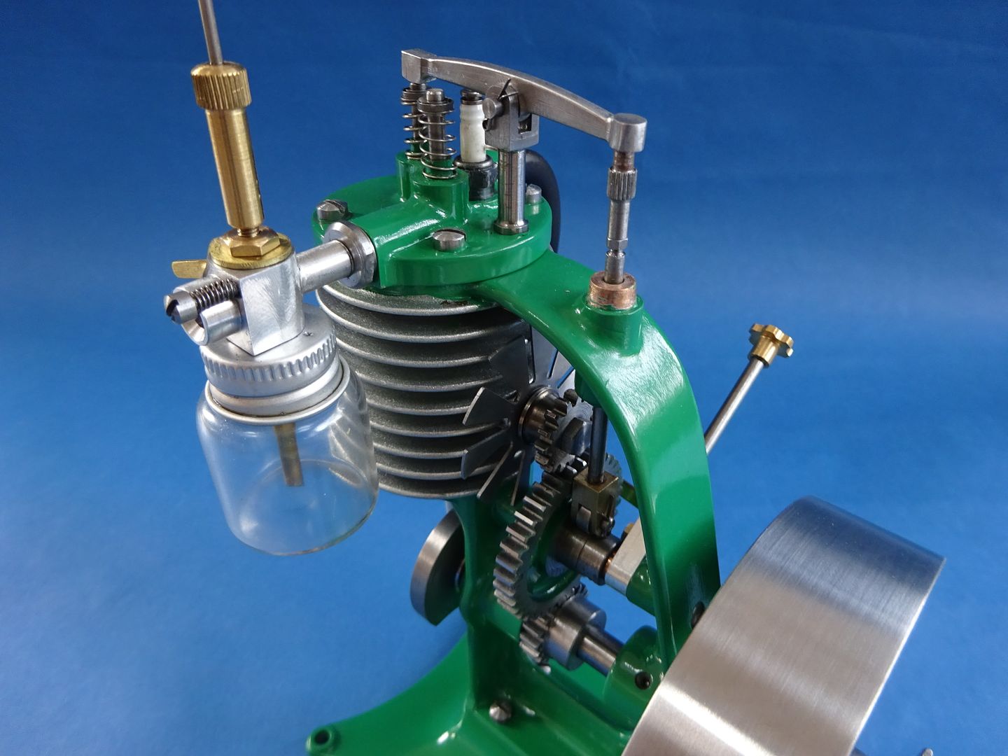
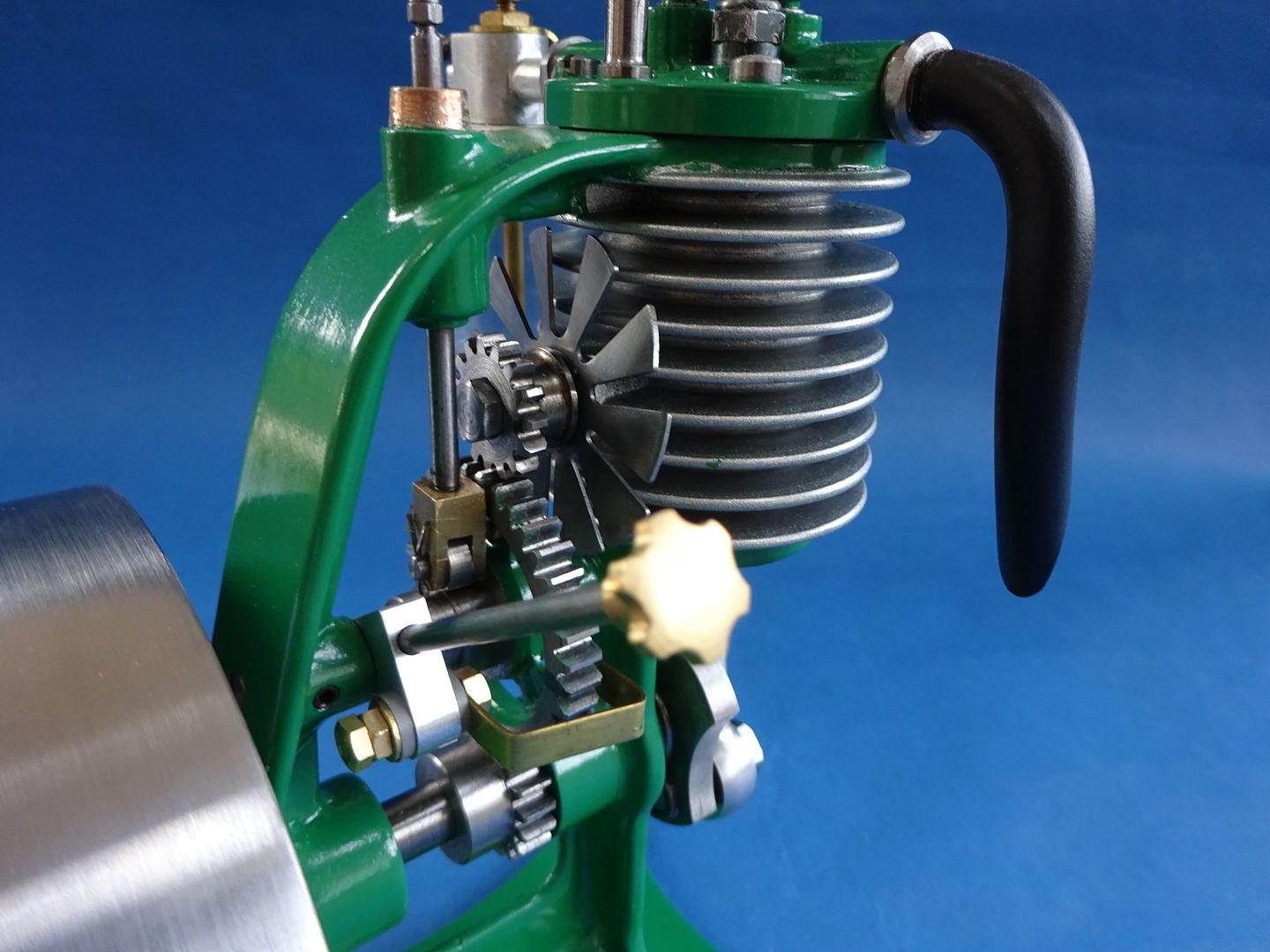
                                            I finally got round to taking some photos of the finished and painted engine. Apart from the green which was darker than I originally planned I'm quite pleased with how it turned out.

                                            #520775
                                            Craig Brown
                                            Participant
                                              @craigbrown60096

                                              Beautiful looking engine! Look forward to a video of it running

                                              #520921
                                              Ron Laden
                                              Participant
                                                @ronladen17547

                                                Very nice indeed, impressed with the fabricated frame and base.

                                                I to look forward to the video I should imagine it will sound good.

                                                Ron

                                                #521547
                                                JasonB
                                                Moderator
                                                  @jasonb

                                                  Thanks for all the appreciative comments

                                                  But onward to the important bit before anyone thinks Unlike a few engines this one seemed to run better after stripping and painting and starts first time after a pull of the cord which I can get 5-6 winds around the starter pully. It's still running quite hot particularly when I lean it out which also ups the revs and makes the throttle a bit more responsive. Richening the mixture a bit slows it down to a more pleasing (to me) speed but then the throttle has little effect.

                                                  I did not play with the timing on the video as it is hard to do up the adjuster one handed and did not want to risk things coming loose as during initial testing that did happen and the brass ignition contact went through the open gears and was spat out the other side in several pieces blush

                                                  The exposed gears and crank make it a bit noisy but it does make for a more interesting engine when running rather than having everything hidden away inside a crankcase and the dirty oil seems to wipe off Ok smiley

                                                  #521553
                                                  John Dean 3
                                                  Participant
                                                    @johndean3

                                                    Looks good Jason. Fuel looks to be a clear liquid, what is it? Could you possibly describe your ignition system as it seems to work very well.

                                                    Thans, John

                                                    #521577
                                                    JasonB
                                                    Moderator
                                                      @jasonb

                                                      For the liquid fueled IC engines I tend to use Colmans fuel which is available from most camping and outdoors type retailers as it is used as a camp stove fuel.

                                                      The Americans sometimes refer to it as "White gas" as it is almost colourless unlike pump gas (petrol) but the main reason I use it is it smells far less so you don't end up with a workshop smelling of petrol fuels and if you bring the engine into the house for display/storage there is no lingering smell.

                                                      As this is an open crank 4-stroke I am running a very small amount of Husqvarna 2-stroke oil and after about a min into the running you can see I've filled up with a slightly stronger mix as there is more of a green tinge to the fuel. Some people add WD40 or the Americans like their marvel Mystery Oil.

                                                      As far as the ignition goes I tend to use the CDI ignitions from S/S in the States this being their single spark unit, you can just see the outer cover of it laying over the battery holder though they are winding the business down and retiring. The unit can be tripped by a hall sensor but also has the option for a pair of simple contacts just by using 2 of the three wires that would have gone to the hall sensor and I much prefer to do it that way. You don't need anything fancy for contacts like you would with a traditional car coil, just two metal contacts, on this engine I have a fixed brass stud in the side of the larger cam gear and an insulated flat brass strip contact on an adjustable are so that when the two meet the circuit is completed and you get your spark.

                                                      Power comes from four AA batteries and I'm using a standard length 1/4 x 32 Rimfire sparkplug with one of S/S's silicon boots as the plug is a bit too close to the exhaust rocker you a more traditional looking brass clip causing the spark to take the easy route and not happen inside the engine. There is a ground wire that completes the circuit back to the CDI which I've just got hooked up to one of the cylinder head screws for now.

                                                      Nearest equivalent from a UK source now that S/S are winding up would be the MCL-1 unit done my Minimag

                                                    Viewing 25 posts - 1 through 25 (of 29 total)
                                                    • Please log in to reply to this topic. Registering is free and easy using the links on the menu at the top of this page.

                                                    Advert

                                                    Latest Replies

                                                    Home Forums I/C Engines Topics

                                                    Viewing 25 topics - 1 through 25 (of 25 total)
                                                    Viewing 25 topics - 1 through 25 (of 25 total)

                                                    View full reply list.

                                                    Advert

                                                    Newsletter Sign-up