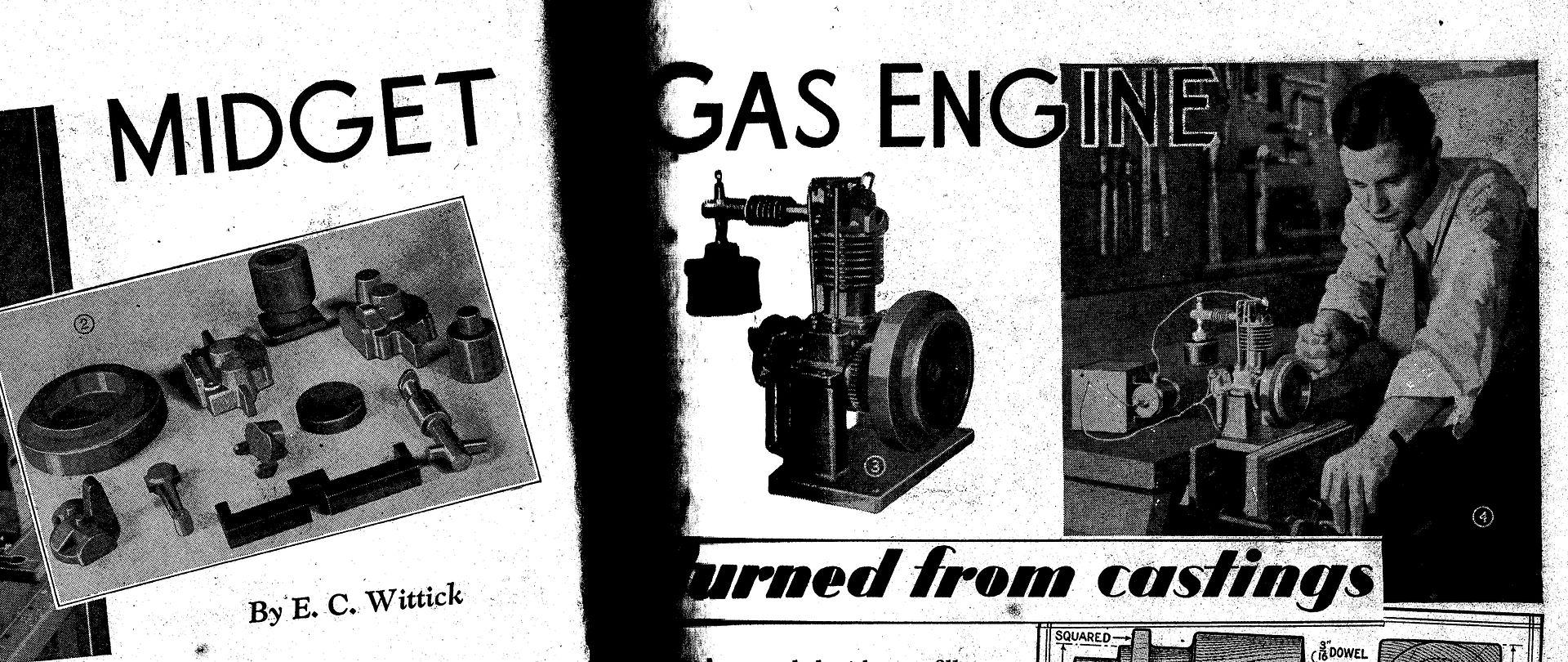
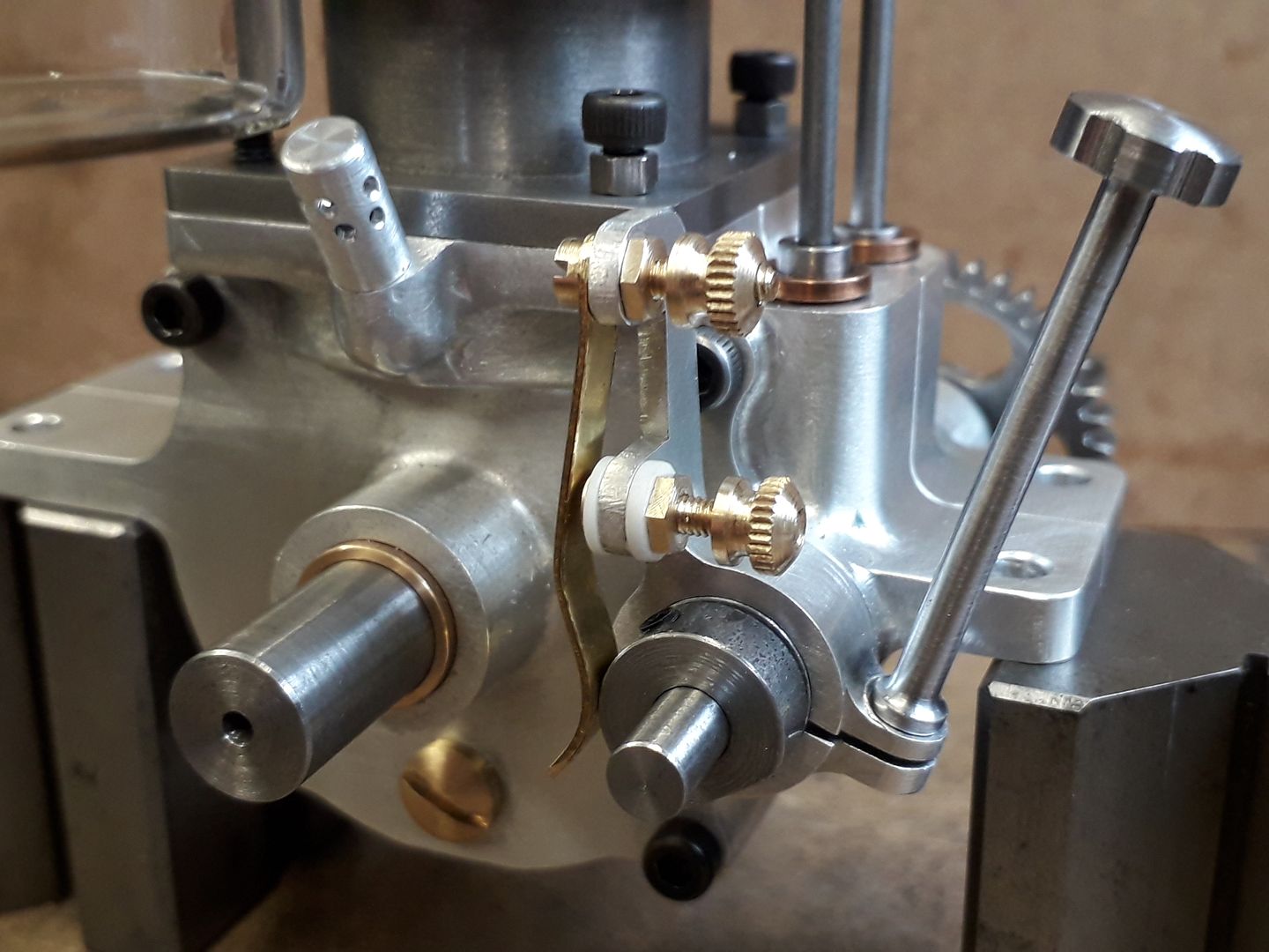
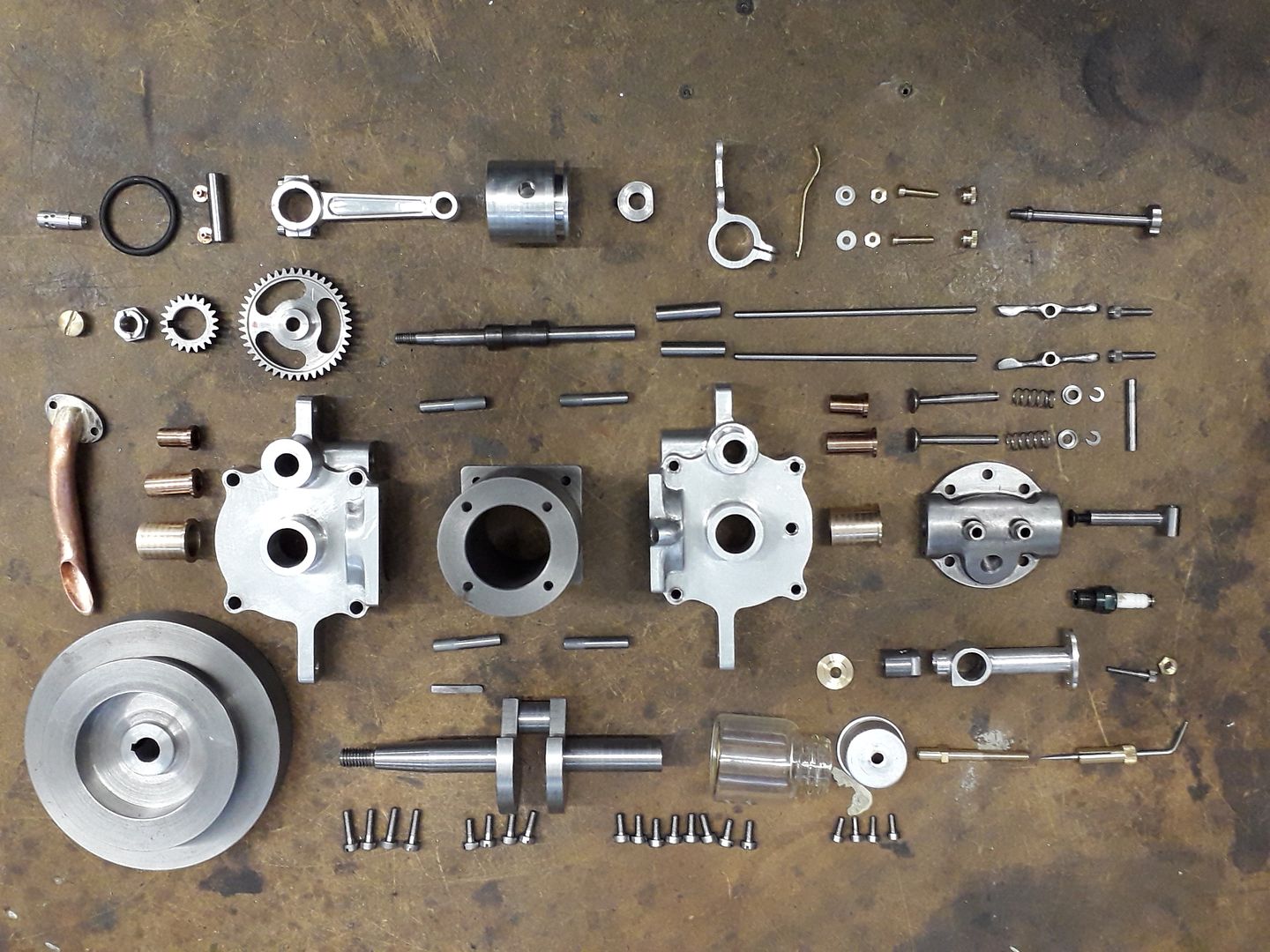
I first became aware of this engine when one popped up as a suggested video on You-tube and I quite liked the look of it. The Video said that the design was in a 1936 issue of Popular Mechanics which detailed making the patterns and a second issue had the working drawings and machining description. After a bit of googling I found the first part on the web but not the second, however the two parts were also published in Popular Mechanics "Shop Notes" from 1938 which I managed to buy an old copy of.

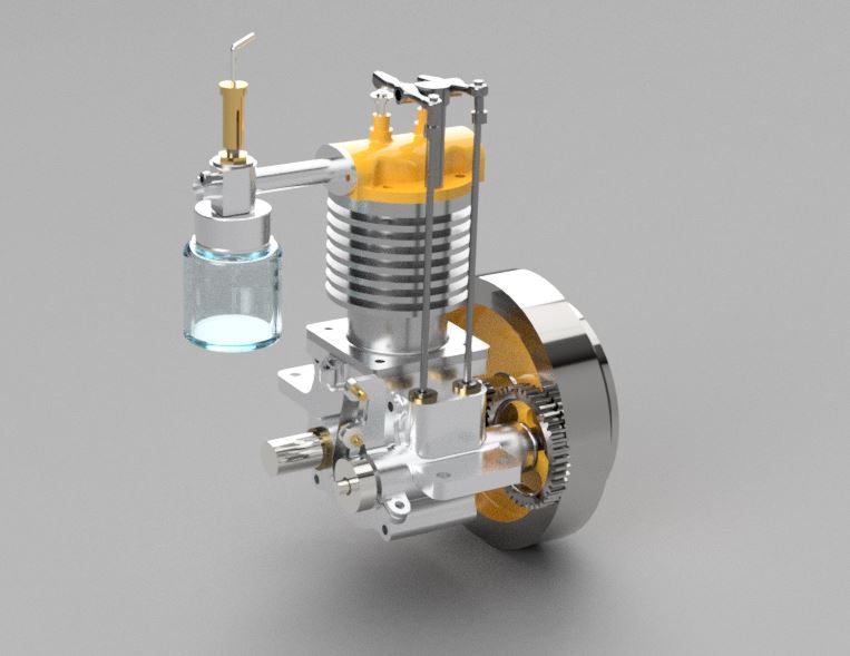
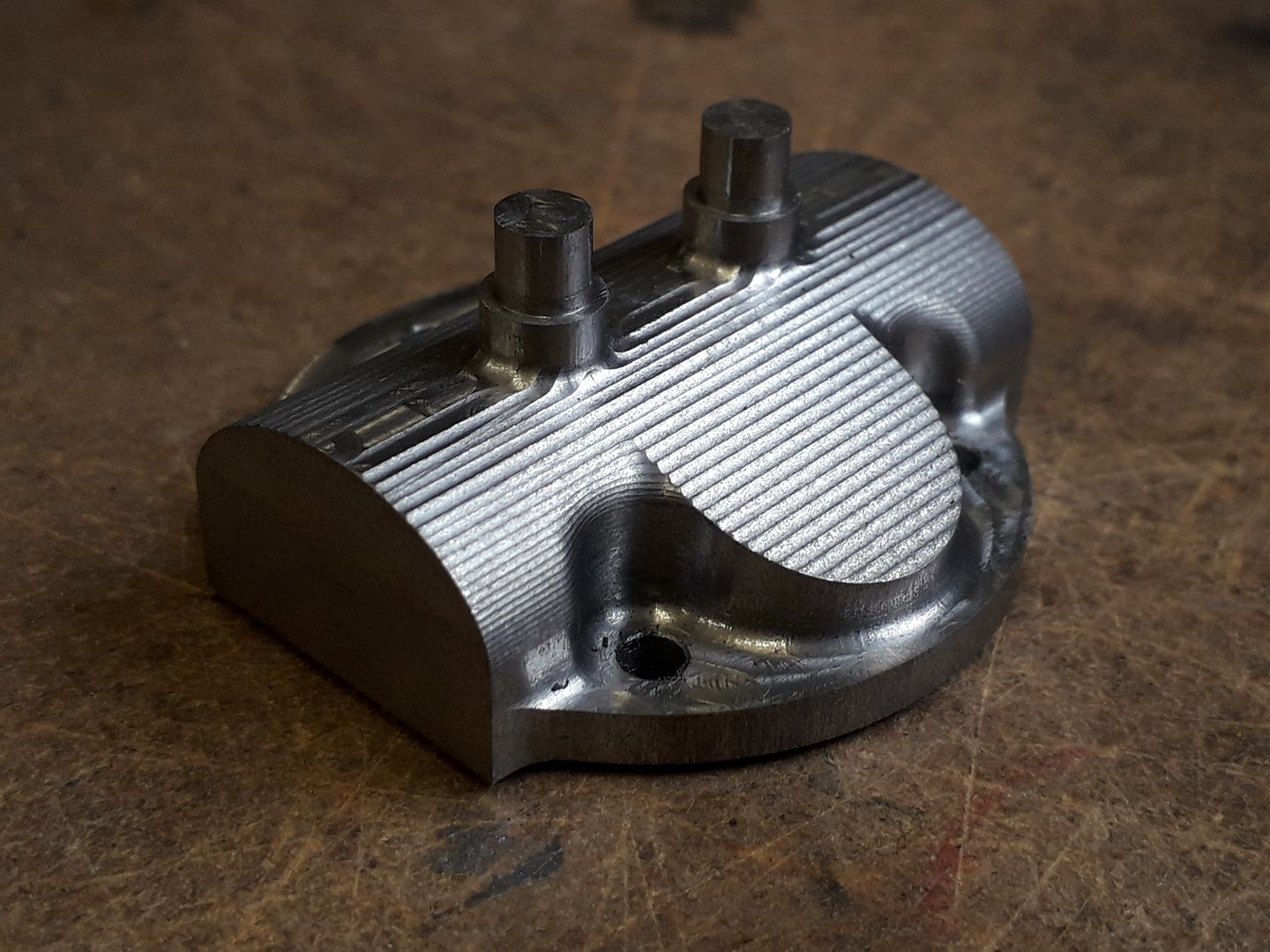
Now you know how I feel about some castings and that combined with a newly acquired CNC mill made the decision to cut from solid an obvious choice and while I was at it a reduction in size from the original 1 1/4" bore down to my usual 24mm bore and a complete metric design. As shown in the magazine there were some rather crude details and lack of refinement so I also set about changing just about every part yet still staying true to the original layout and the look of an old engine not a clunky barstock engine. A few evenings work in Alibre and the basic design was ready.

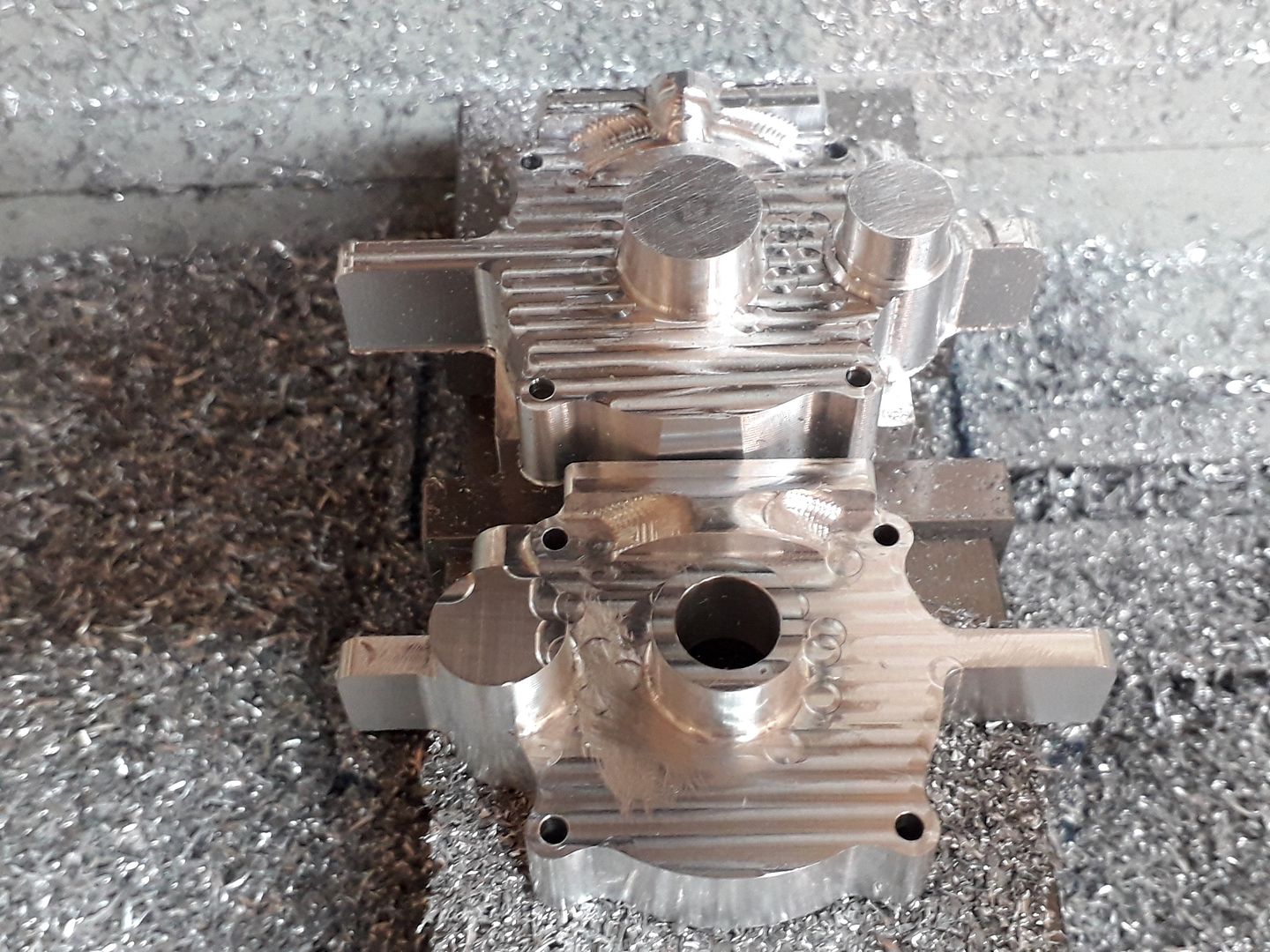
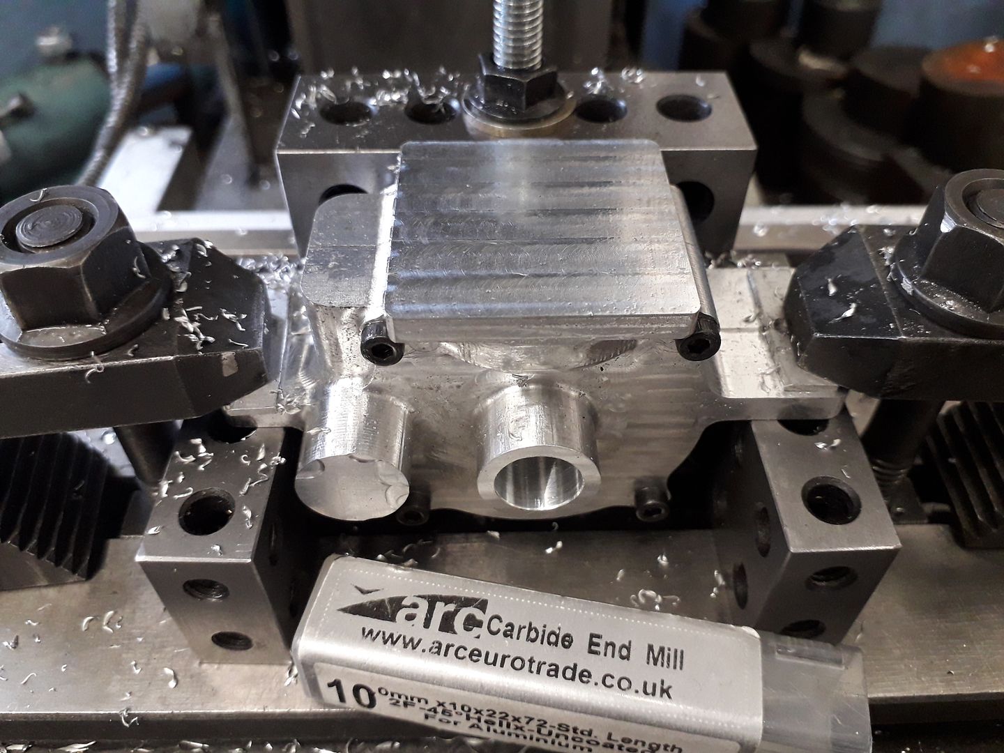
The parts that needed the most work and that would make or break the project were the two crankcase halves so I started with them by exporting my design from Alibre to F360 where I used the CAM to create the codes for cutting the crankcases.
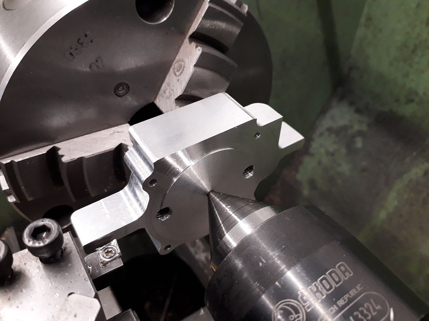
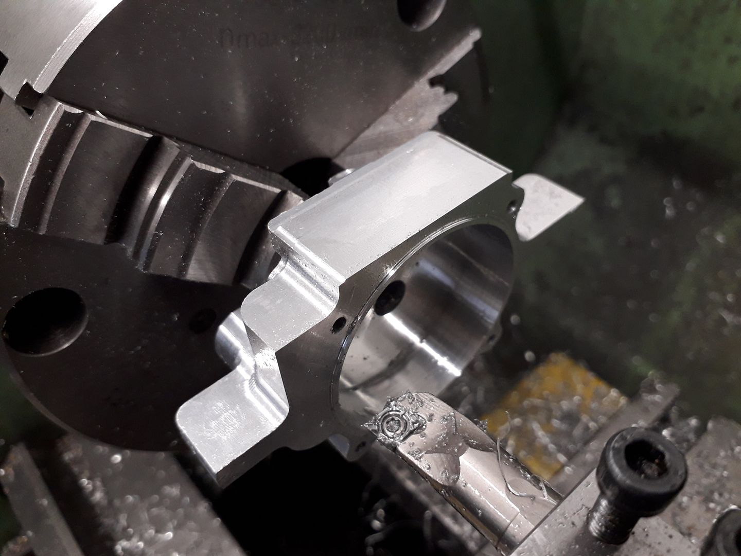
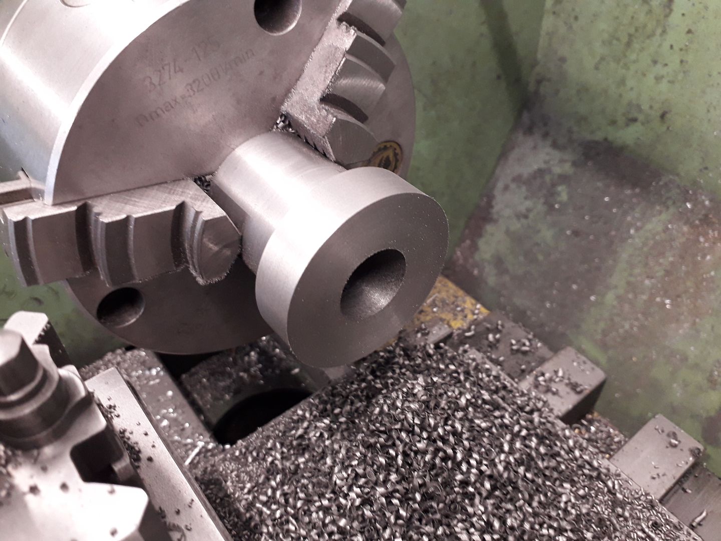
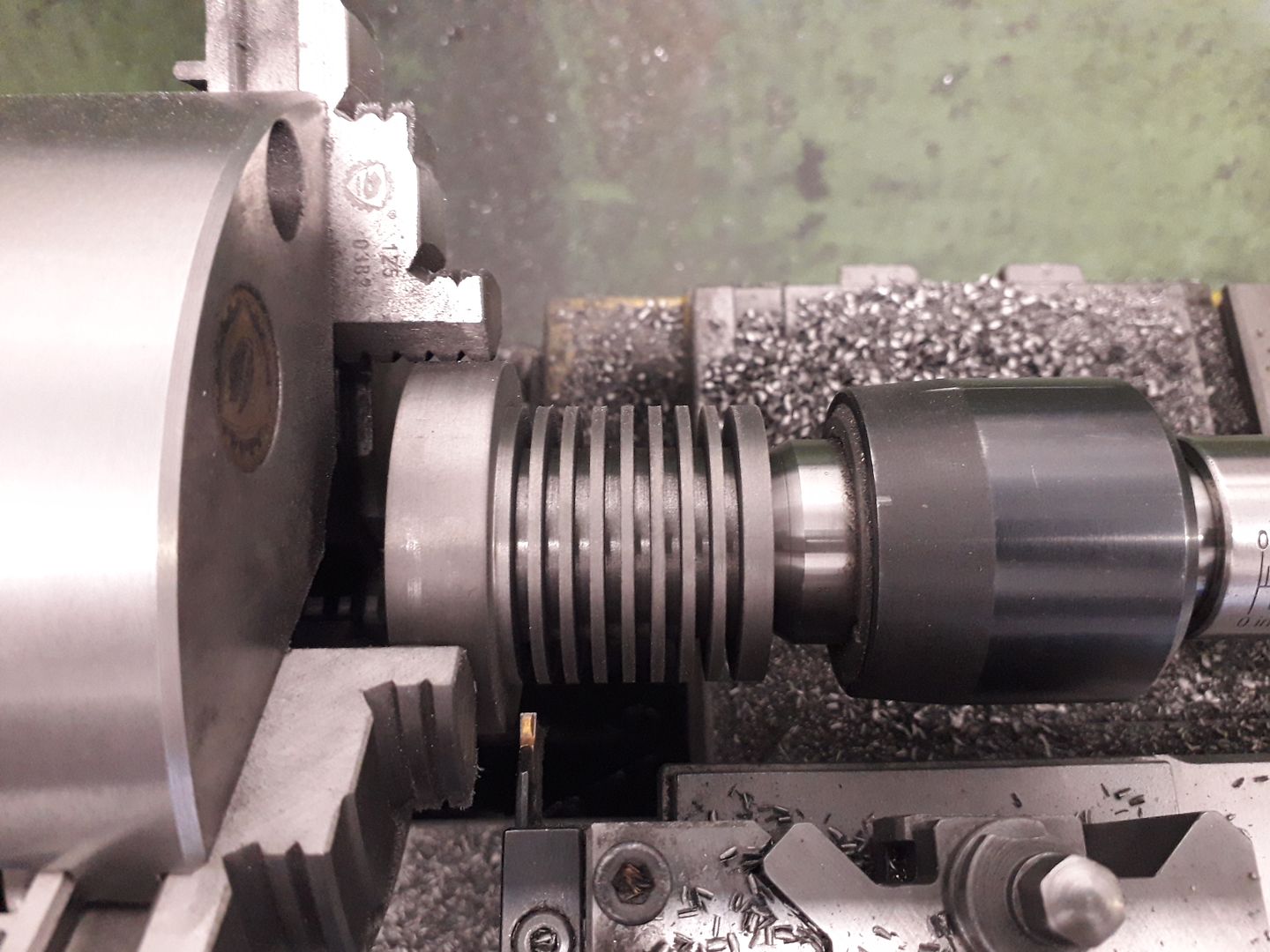
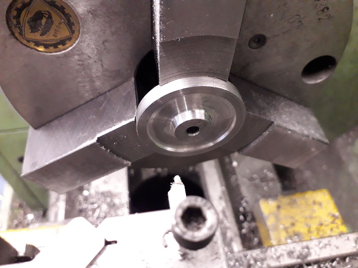
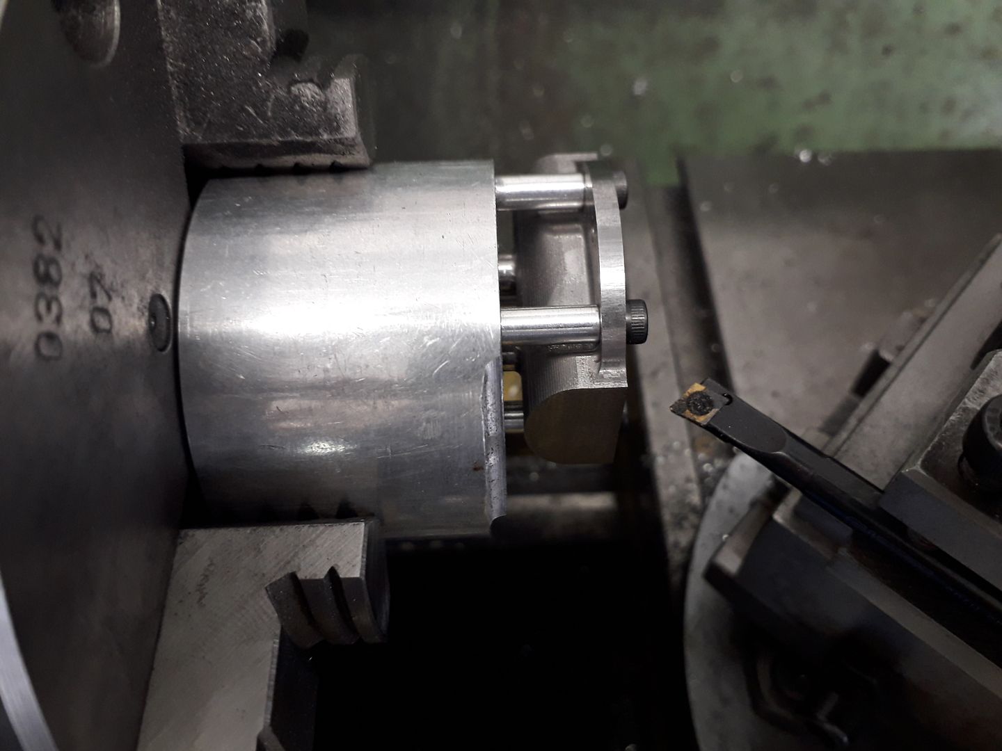
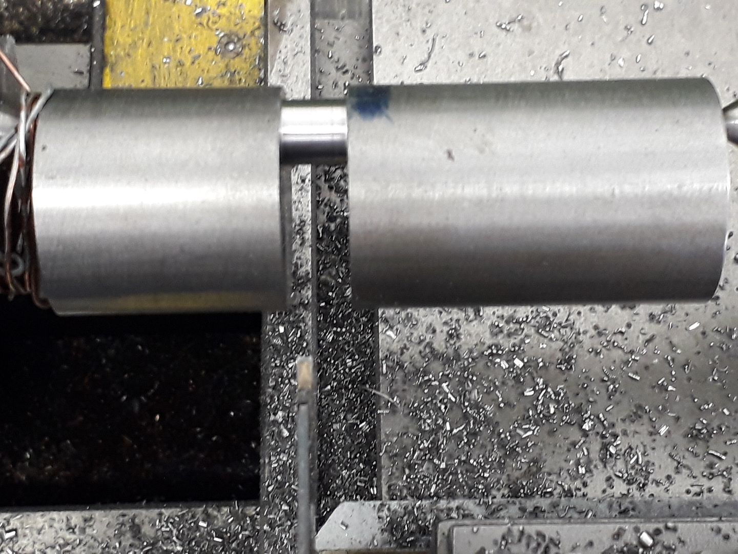
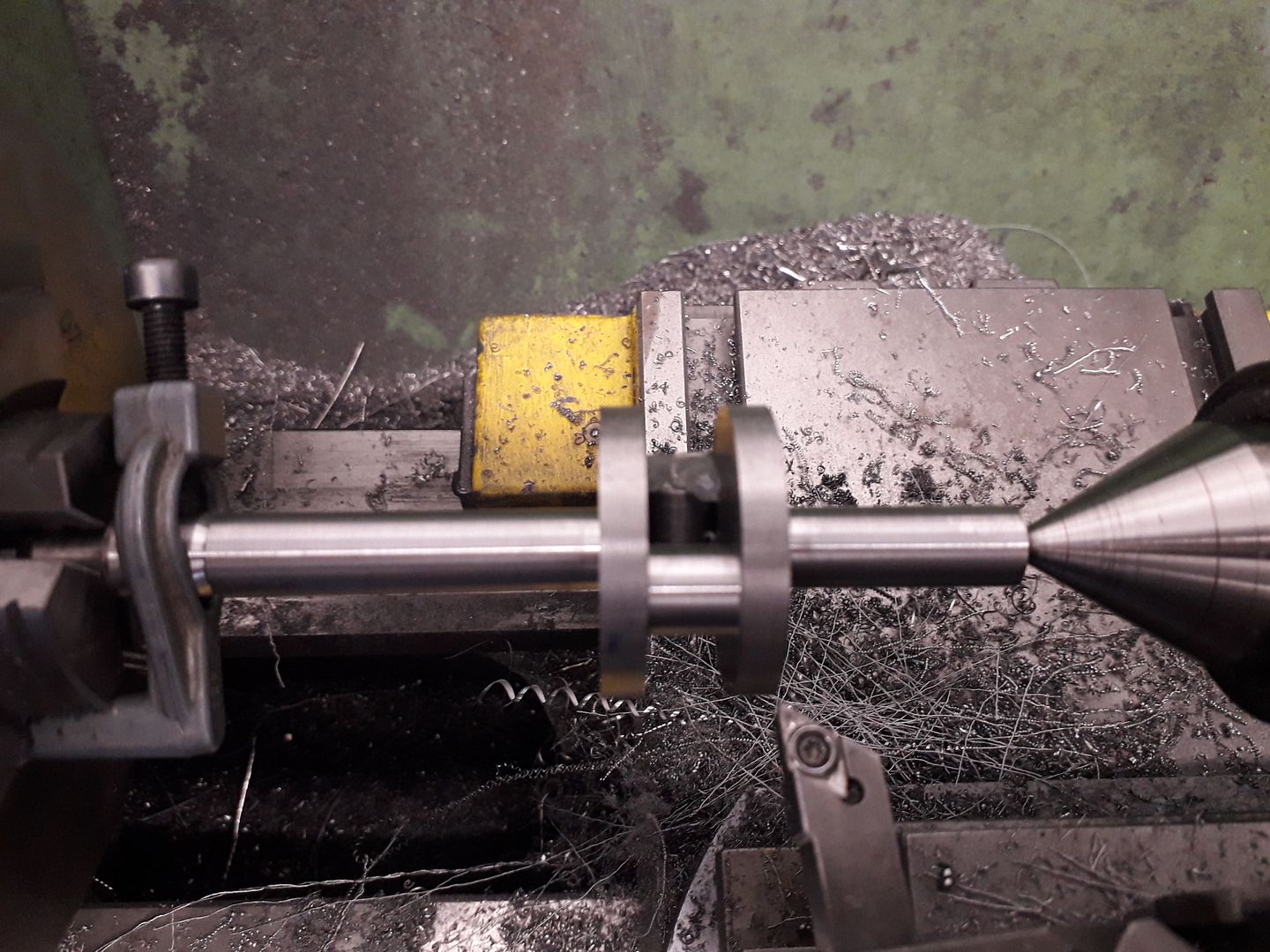
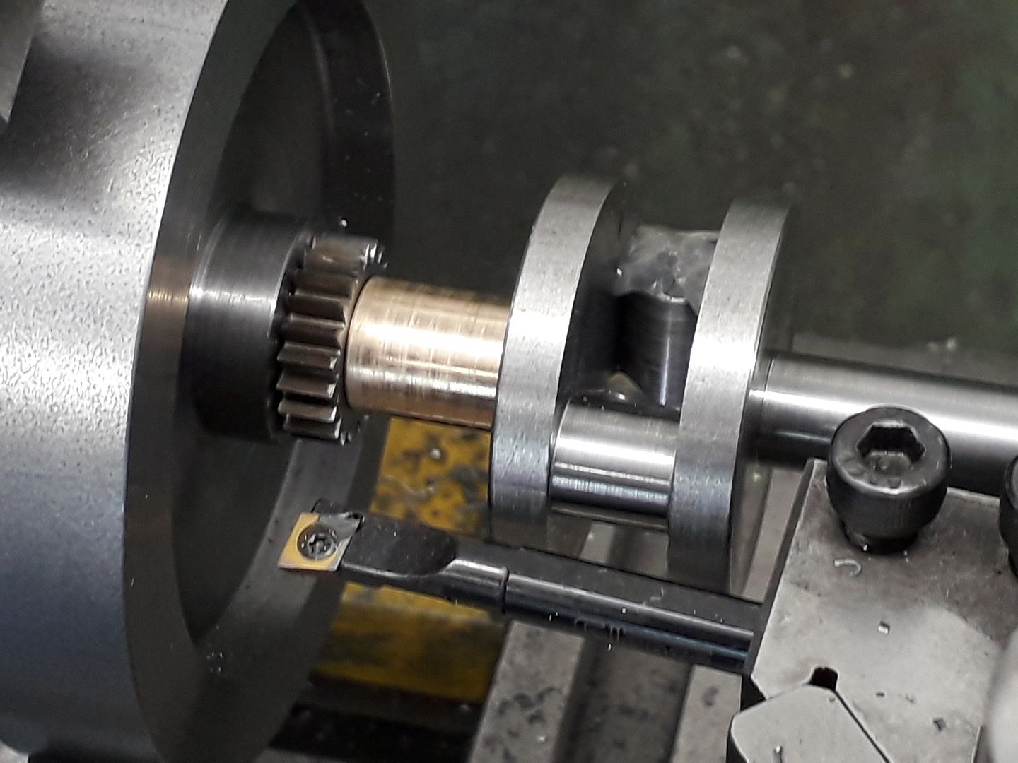
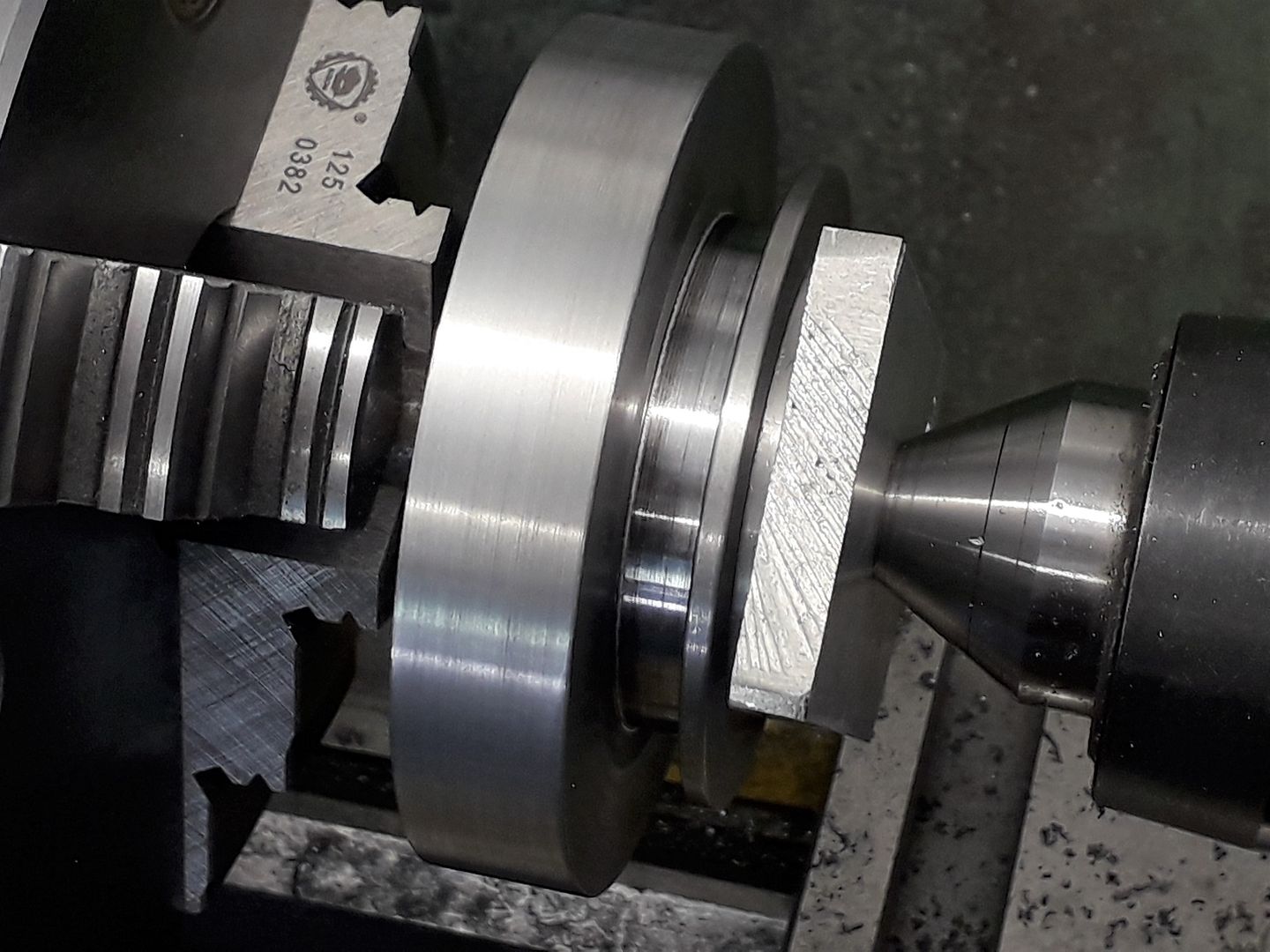
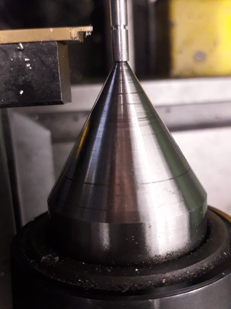
Rather than make nesting jaws to mill the inside I decided to use the lathe, firstly bringing the case down to thickness with the tailstock giving support as there was not much to hold during the interrupted cuts.

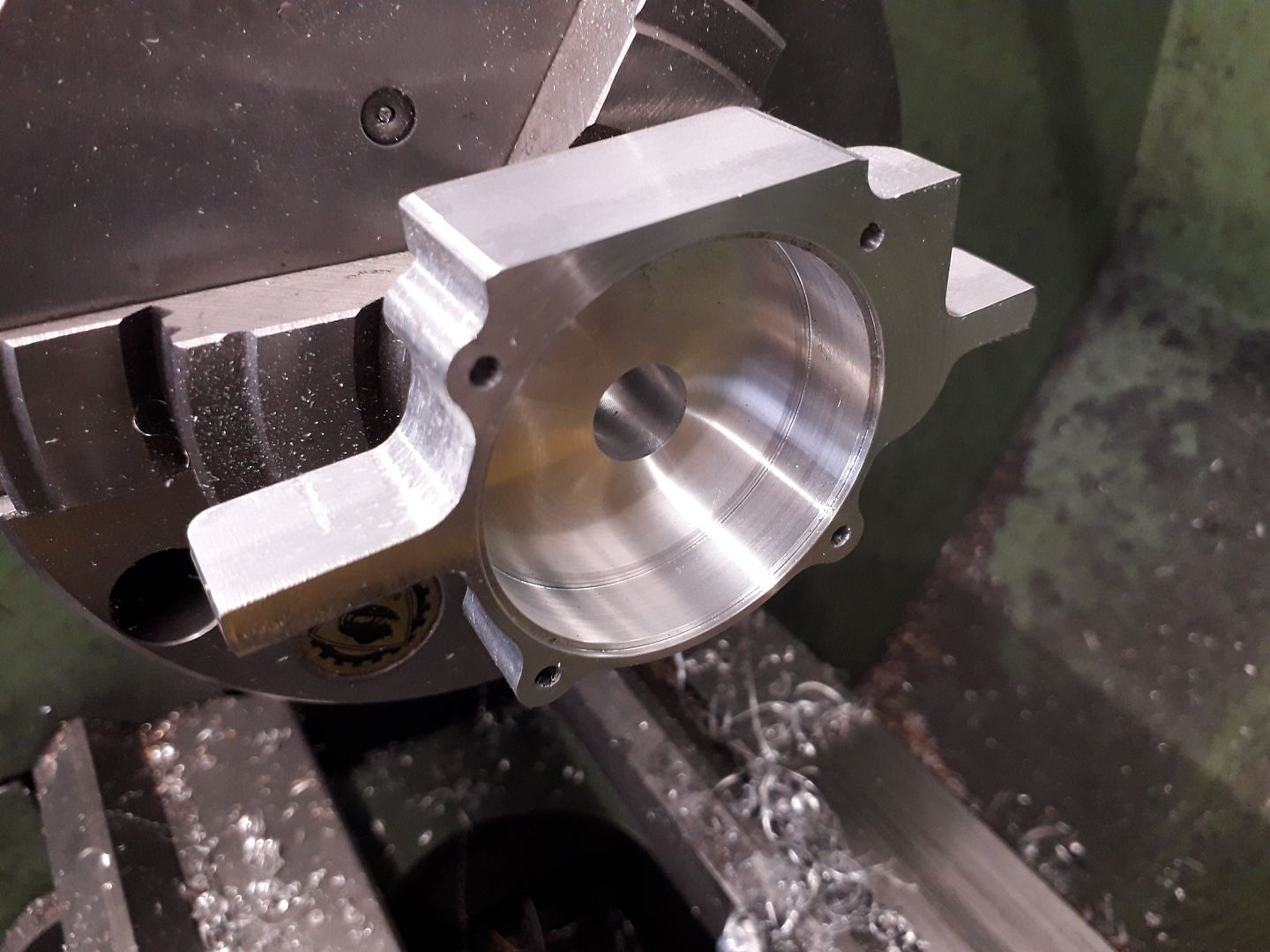
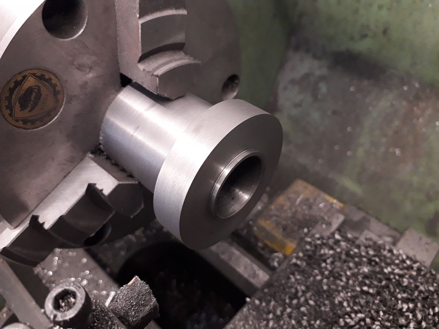
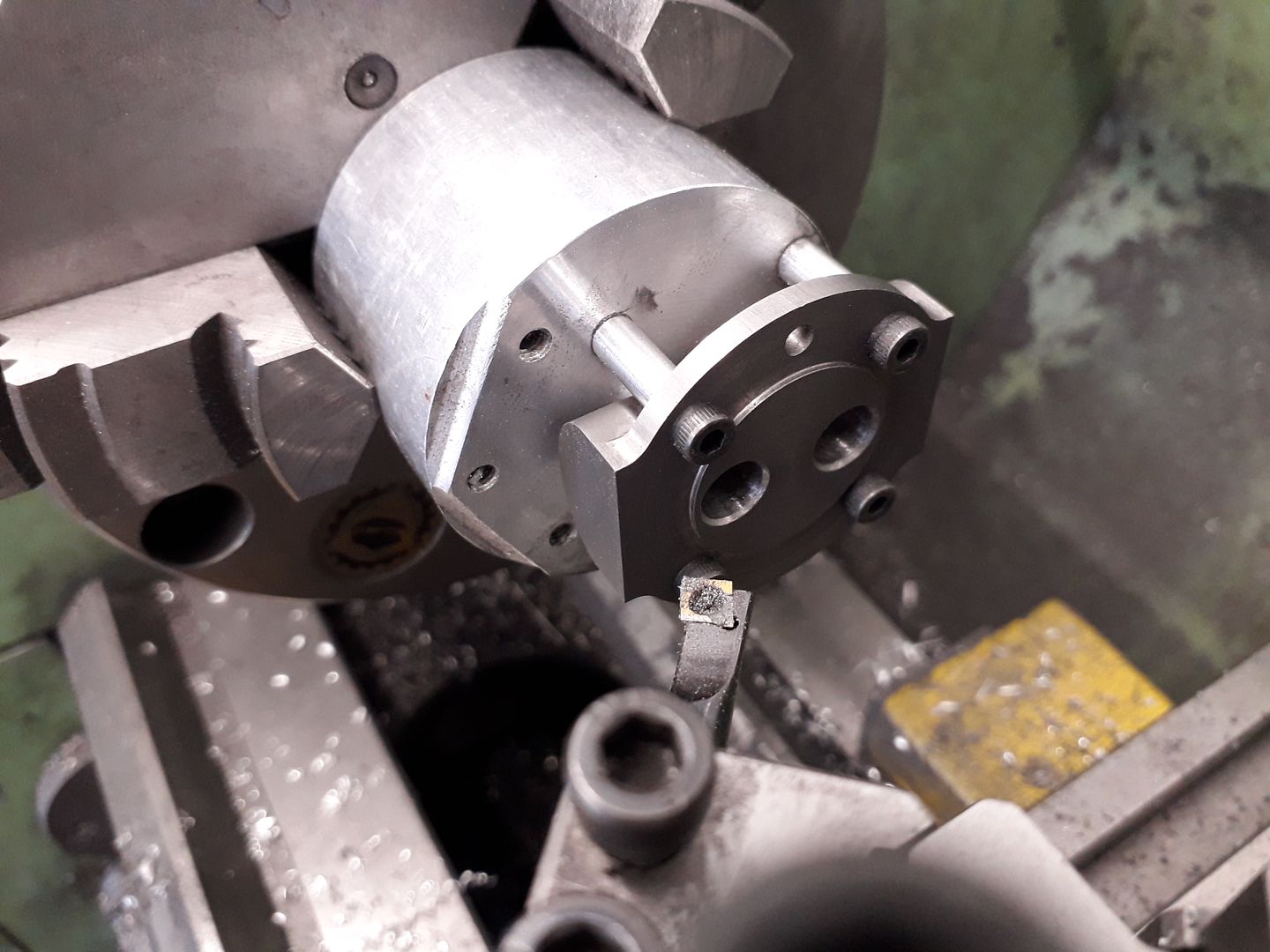
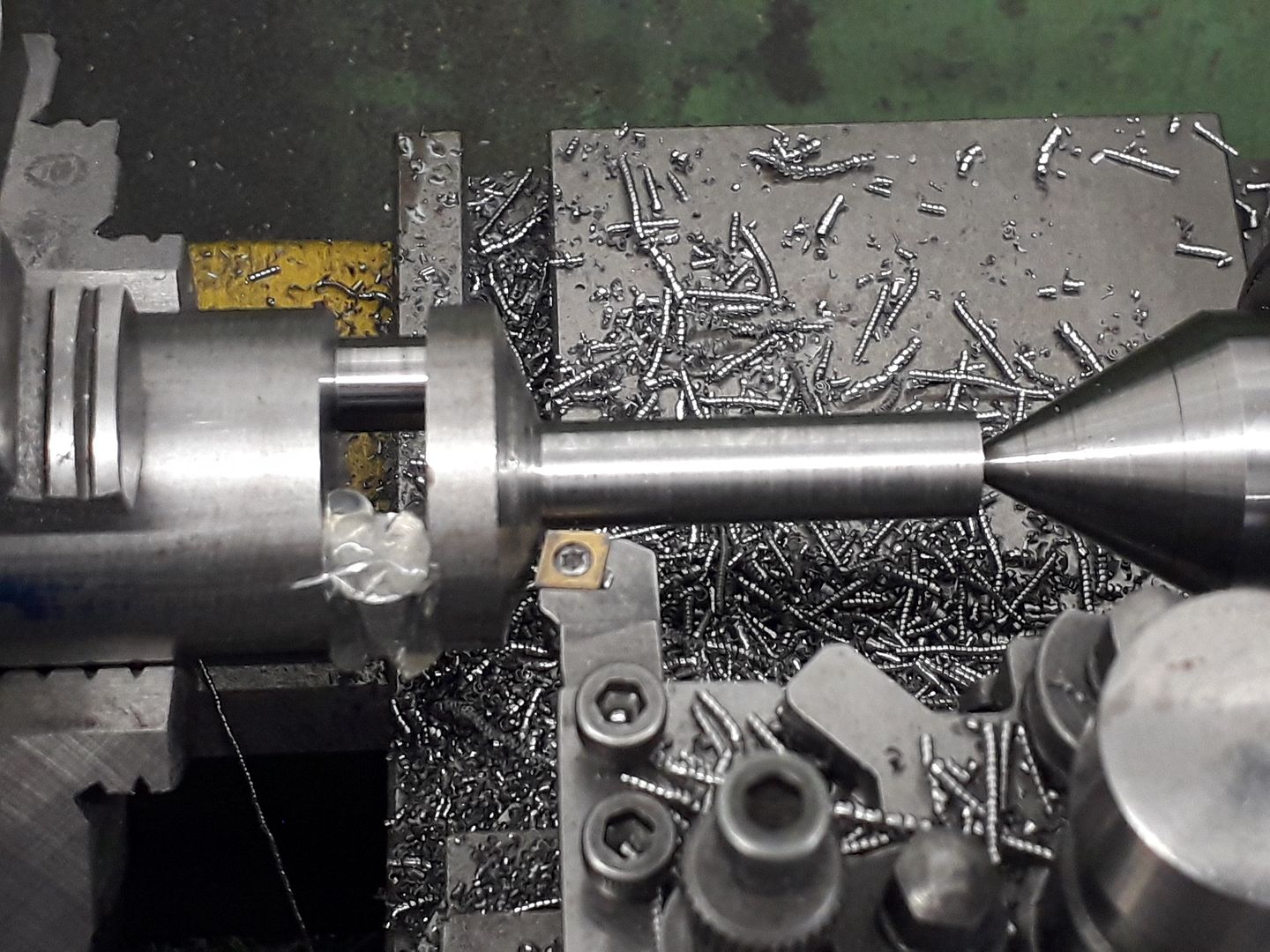
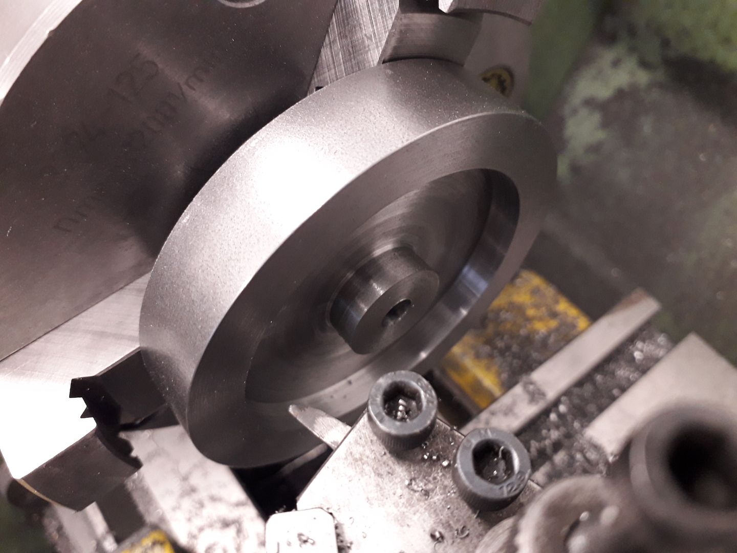
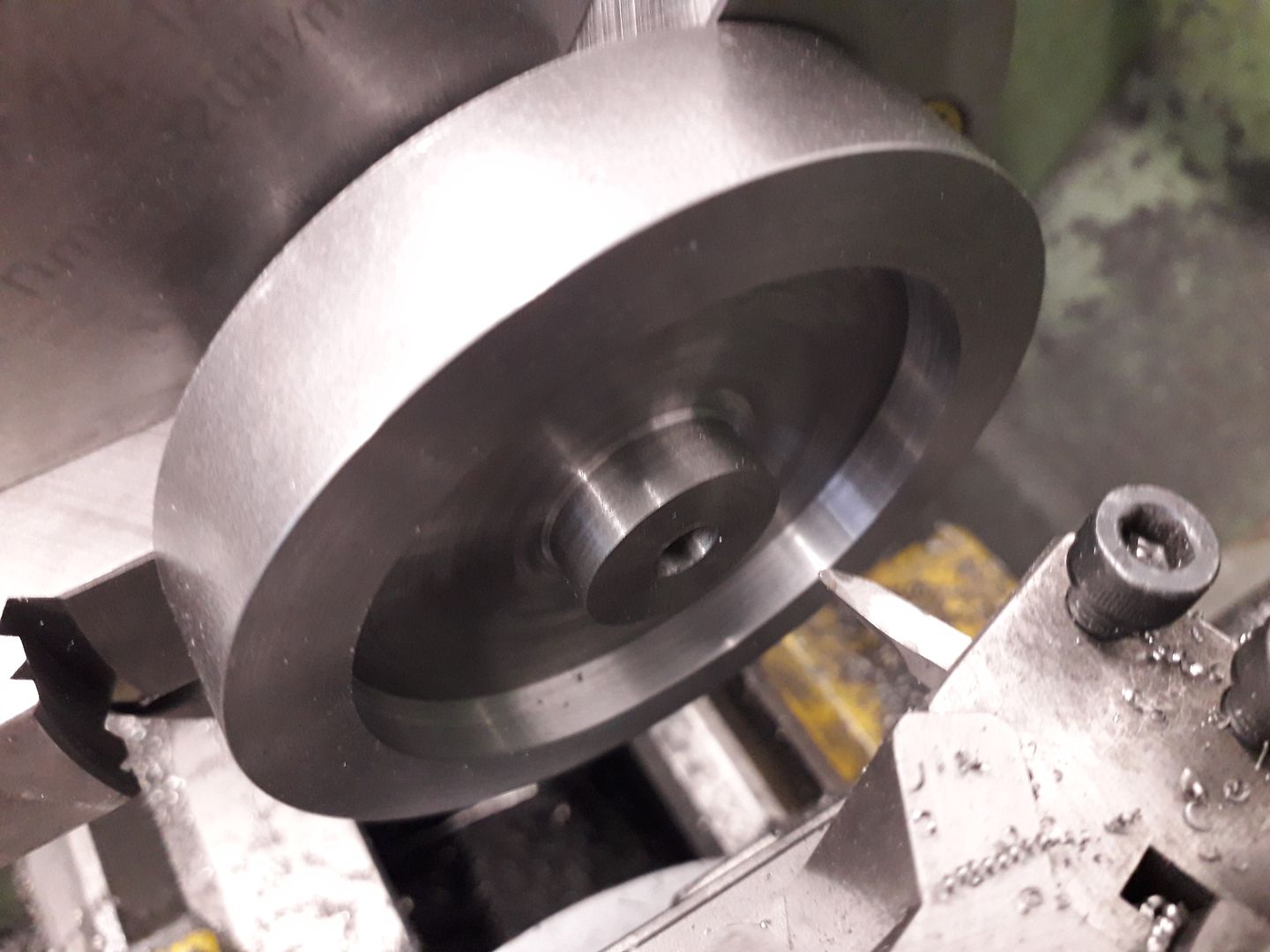
Followed by boring out the space for the crank and an undersize bearing housing. You can just see that I also included a small locating recess for a spigot on the other half, the original did not have this but I felt it would help keep the two halves lined up.

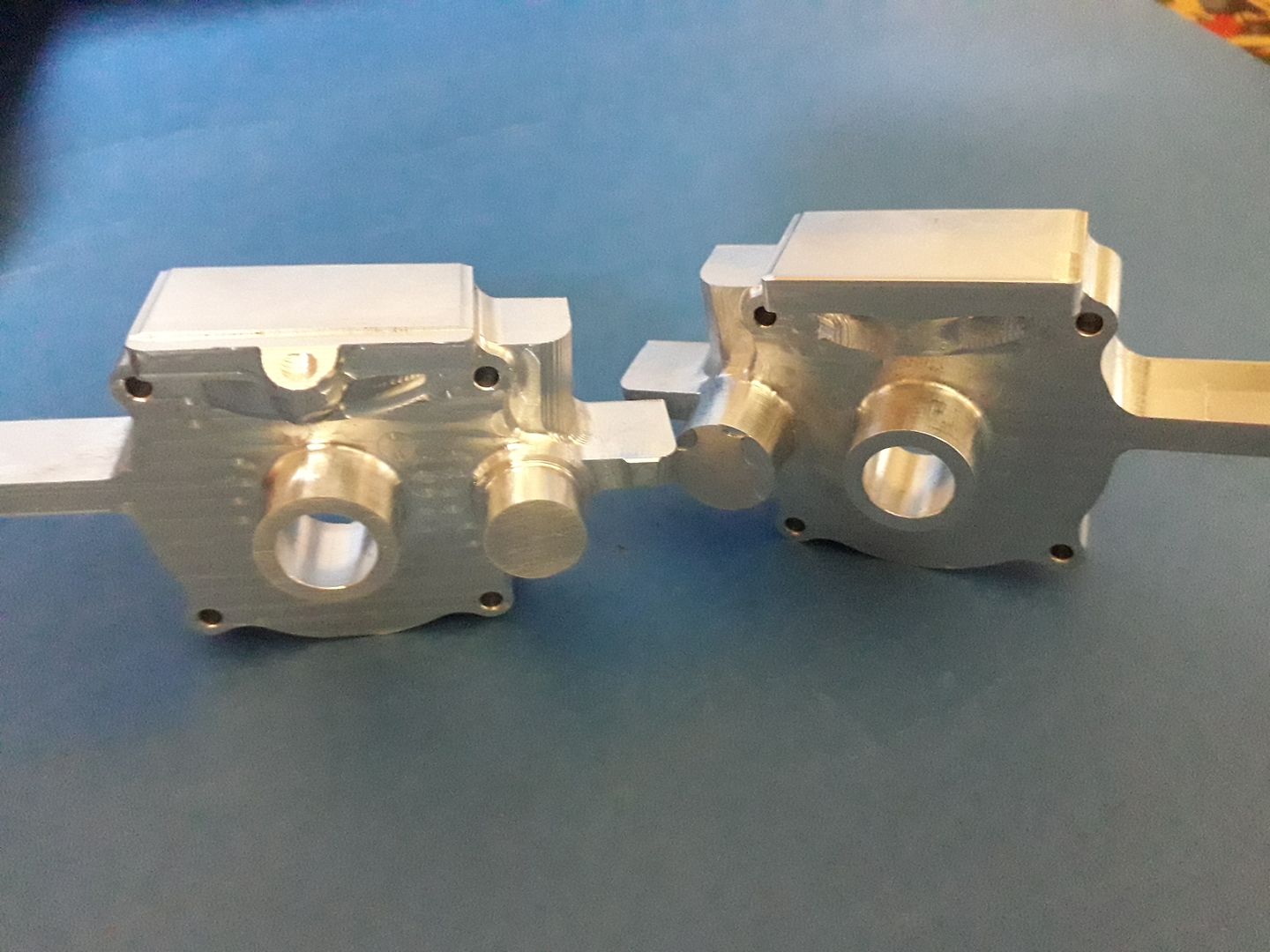
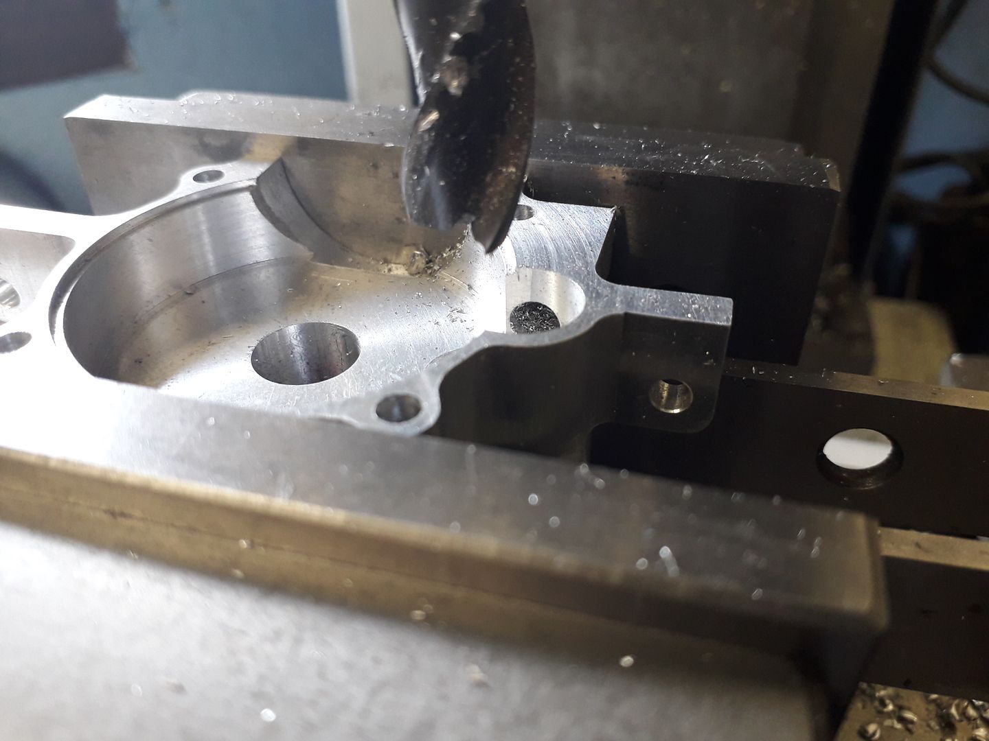
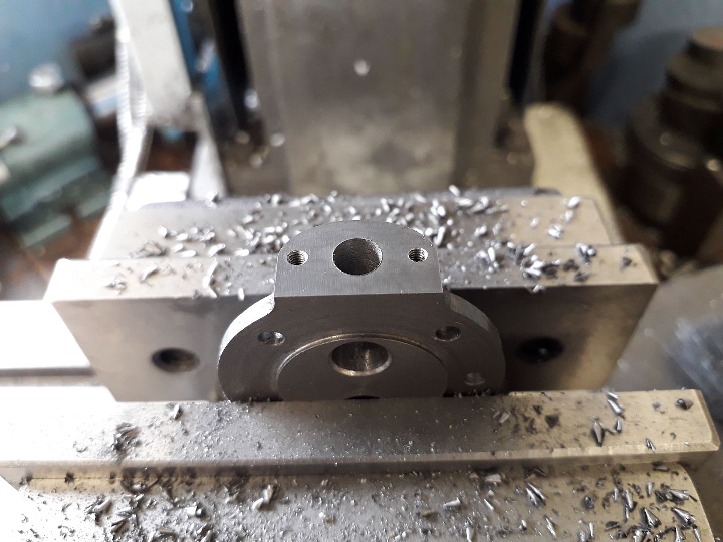
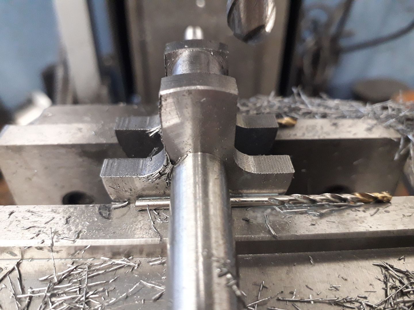
The rear half was milled out with a few changes to the CAM to take into account what I had learnt doing the front half, it is basically a mirror image with the addition of a boss for the vent.

This was then turned in much the same way except a spigot was left rather than the recess.

I also started cleaning up the machining marks with needle & reiffer files and Emery cloth.

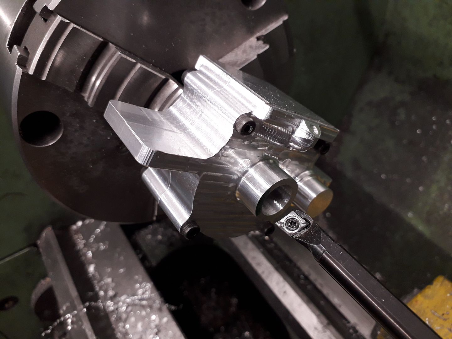
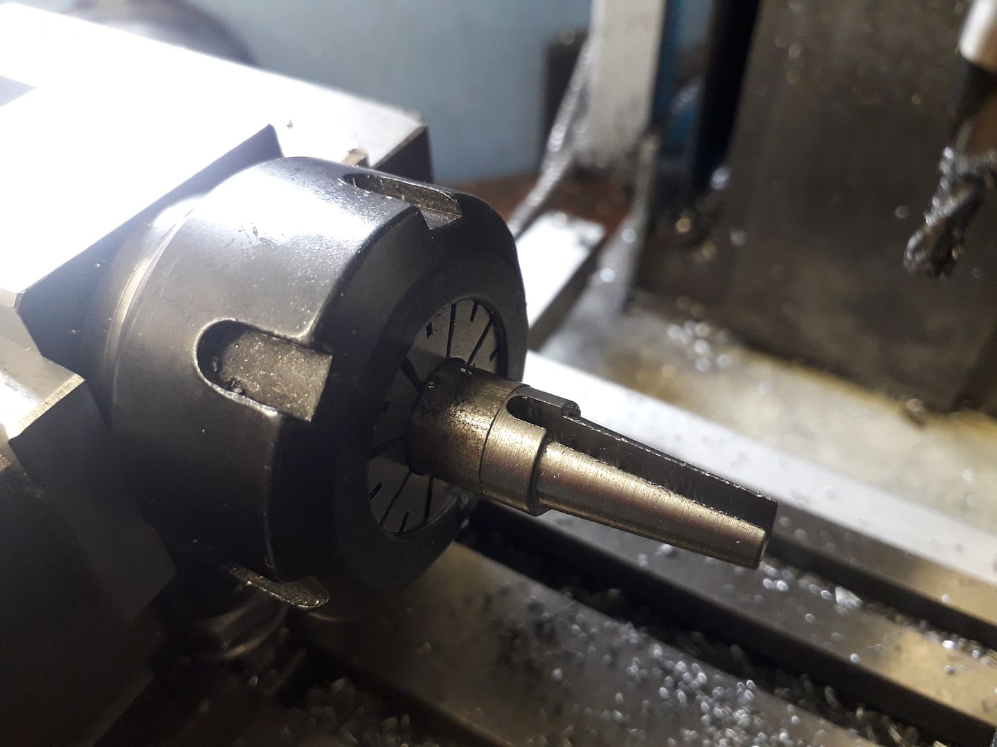
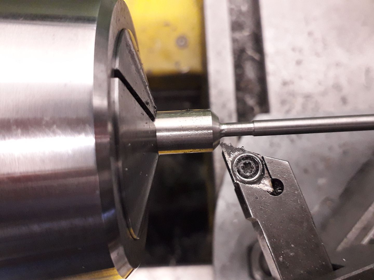
The screw holes were reamed to 4mm and some dowels made with M3 tapped holes each end. These also help keep the two halves lined up and are again another feature of my own. It was now possible to hold both halves in the lathe to bore both bearing housings at one setting to ensure perfect alignment.

Ron Laden.


