Steam operated drain cocks

Advert

Steam operated drain cocks

Home Forums General Questions Steam operated drain cocks

Viewing 23 posts - 1 through 23 (of 23 total)
  • Author
    Posts
  • #113729
    ed milton
    Participant
      @edmilton29925

      Dose any one know if there has been an article or drawings for steam operated drain cocks in ME mag?

      Advert
      #22505
      ed milton
      Participant
        @edmilton29925
        #113731
        Stewart Hart
        Participant
          @stewarthart90345

          Hi Ed

          Quite a few members at my club use them, I've drawn them and made a few sets and passed them on, so far they seem to have worked, if you PM me with your email adress I'll pass the drawing on.

          Stew

          #446980
          Frederick Michael WICKENS 1
          Participant
            @frederickmichaelwickens1

            Dear Stewart

            I have been trying to sort this out, steam operated drain cocks for ages, I would be interested with any drawing.


            Kind regards

            Mick W


            Edited By JasonB on 16/01/2020 15:41:42

            #447054
            Essm
            Participant
              @essm

              Hi Guys

              Search in Wikipedia for steam drain cocks for a drawing and then you can also follow various links

              Edited By Essm on 16/01/2020 21:55:03

              Sorry – search should be for Automatic cylinder cocks and not as previously shown

              Edited By Essm on 16/01/2020 22:03:19

              Please disregard this post altogether  – I am searching for correct link

              Edited By Essm on 16/01/2020 22:10:52

              #447055
              Nick Clarke 3
              Participant
                @nickclarke3

                Looking at the index to Model Engineer at **LINK**

                There are two references to 'Steam Operated Draincocks' but that doesn't mean there are not others under references to particular model designs.

                Model Engineer 2007 Volume 198 Issue 4292 Page 143
                Model Engineer 1985 Volume 155 Issue 3758 Page 165

                #447061
                Essm
                Participant
                  @essm

                  Hi again – please try this link for a drawing

                  **LINK**

                  #447067
                  Fowlers Fury
                  Participant
                    @fowlersfury

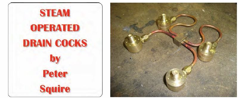
                    In 2015 there was a short article on Steam Operated Drain Cocks in David Carpenter's Model Engineers Website. I like the design and eventually plan to make a set as described by Peter Squire.

                    Usual "for personal use only" applies to downloads, so check the website:-
                    **LINK**

                    Doubt there's a problem with me showing the article's heading:-
                    capture.jpg

                    (You could PM me if interested)

                    #447071
                    nigel jones 5
                    Participant
                      @nigeljones5

                      I tried some a few yrs back….wasnt impressed

                      #447075
                      Paul Lousick
                      Participant
                        @paullousick59116

                        My preference is for manually operated drain cocks.

                        If the engine starts to prime , you can open a manual drain to release pressure and prevent damage to the cylinder, piston, etc.

                        Paul.

                        #447080
                        Brian Baker 2
                        Participant
                          @brianbaker2

                          Greetings Paul, I have been using steam operated drain cocks for some time, and they are completely controllable, just like taper cocks, just close the steam valve and they open to clear condensate, but with the added bonus that they will open automatically if you get a hydraulic lock.

                          Regards

                          Brian

                          #549334
                          Hans Hogendoorn
                          Participant
                            @hanshogendoorn60983

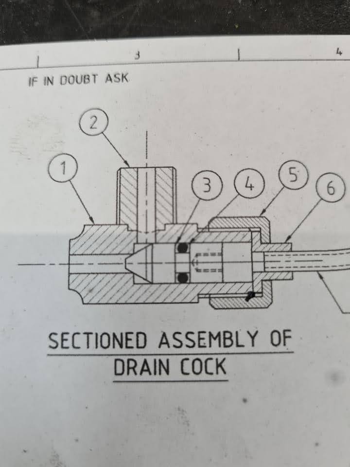
                            Maybe someone can help me, I downloaded some time ago this picture from a steam operated drain cock. This is all I have , is there someone recognize this part ? And maybe can help me with the rest?

                            Kind regards Hans

                            #549591
                            Daggers
                            Participant
                              @daggers

                              Hans,

                              sorry but I don’t recognise that image.

                              when i was looking for information on this subject I found this website, might be worth a look.

                              http://nelsonslocomotive.com/Heisler/Engine/CylinderCocks/CylinderCocks.htm

                              #549608
                              nigel jones 5
                              Participant
                                @nigeljones5

                                1. drain in

                                2. drain out

                                3. valve head

                                4. O ring

                                5. Gland nut

                                6. ferrule

                                7. Out of shot – live steam line

                                Simples – perhaps all that time spent trying to get them to work wasnt a complete waste! Whats not shown is that you will also need a steam relief valve to release pressure to operate the valve.

                                #549619
                                Hans Hogendoorn
                                Participant
                                  @hanshogendoorn60983

                                  Thanks !

                                  #549620
                                  Hans Hogendoorn
                                  Participant
                                    @hanshogendoorn60983

                                    Thanks !

                                    #549685
                                    duncan webster 1
                                    Participant
                                      @duncanwebster1

                                      I think it would work better with 2 connected to the cylinder and 1 as outlet. The drawing shows the OD of 1 not threaded, which agrees

                                      #549693
                                      Another JohnS
                                      Participant
                                        @anotherjohns

                                        I made some from the US model engine maker from a long time ago. I made my copies about 10-15 years ago now.

                                        Work great! Piston valve engine, so wanted something that would act as a relief valve if required.

                                        The one Hans shows above would be better than the ones I made; rather than annealing brass disks, the o-ring makes it simpler.

                                        Great little addition to a locomotive.

                                        #549697
                                        John Olsen
                                        Participant
                                          @johnolsen79199

                                          Sorry Duncan, 1 is the end that should connect to the cylinder. The pressure from the steam on the other end holds the valve on the seat. When there is no pressure there, any pressure in the cylinder can open the valve, allowing it to drain. The ones on my steam launch are just like the one shown, and they work fine. If the pressure in the cylinder gets high enough, say from trying to compress water, it can overcome the steam pressure on the other end and vent anyway, so they act as a relief valve, although I have also provided separate relief valves as well. The operating valve should be a changeover type, so that in one position it connects live steam to the valve, and in the other it connects the cylinder end of the valve to atmosphere.

                                          The operating cylinder part needs to be big enough to hold the valve on its seat, but not so much bigger that it won't act as a relief valve. The ratio of the areas will approximately determine the pressure at which it opens.

                                          I don't have drawings of mine, they were made by eye from a sketch, and they would be a bit big for all but the largest of model locos.

                                          John

                                          #549737
                                          Martin Johnson 1
                                          Participant
                                            @martinjohnson1

                                            I cosidered this type of design for my steam lorry – a large piston valve engine. I was cocerned that they would be rather poor at pressure relief because you would get the live steam line full of codensate. In the event of hydraulic lock on the engine, you have to shift a load of condensate in the actuation line – with it's own inertia. So I concluded it would not prevent damage to the engine. If someone has evidence to the contrary, I would be pleased to hear it.

                                            Martin

                                            #549780
                                            nigel jones 5
                                            Participant
                                              @nigeljones5

                                              Duncan – I opted for no.1 as it has a much lower surface area when closed so whould require less pressure to hold it shut, but either way should work…..I think

                                              #549783
                                              duncan webster 1
                                              Participant
                                                @duncanwebster1

                                                Consider it my way round. The diameter of port 1 scales at half the outside diameter of the Oring, so the areas are 4:1. The area exposed to cylinder pressure is 3/4 of that exposed to boiler steam pressure, and so if cylinder pressure is 1.333 * boiler pressure the valve will open. The other way round you need cyl pressure = 4* boiler pressure to open it.

                                                As Fizzy says, both work. The drawing implies port 1 is exhaust as there is no thread to secure it.

                                                #549797
                                                Baz
                                                Participant
                                                  @baz89810

                                                  Totally agree with Duncan

                                                Viewing 23 posts - 1 through 23 (of 23 total)
                                                • Please log in to reply to this topic. Registering is free and easy using the links on the menu at the top of this page.

                                                Advert

                                                Latest Replies

                                                Home Forums General Questions Topics

                                                Viewing 25 topics - 1 through 25 (of 25 total)
                                                Viewing 25 topics - 1 through 25 (of 25 total)

                                                View full reply list.

                                                Advert

                                                Newsletter Sign-up