Alibre There Eventually – Sort of

Advert

Alibre There Eventually – Sort of

Home Forums CAD – Technical drawing & design Alibre There Eventually – Sort of

Viewing 25 posts - 1 through 25 (of 56 total)
  • Author
    Posts
  • #654494
    Nigel Graham 2
    Participant
      @nigelgraham2

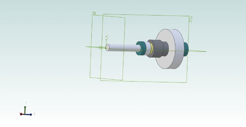
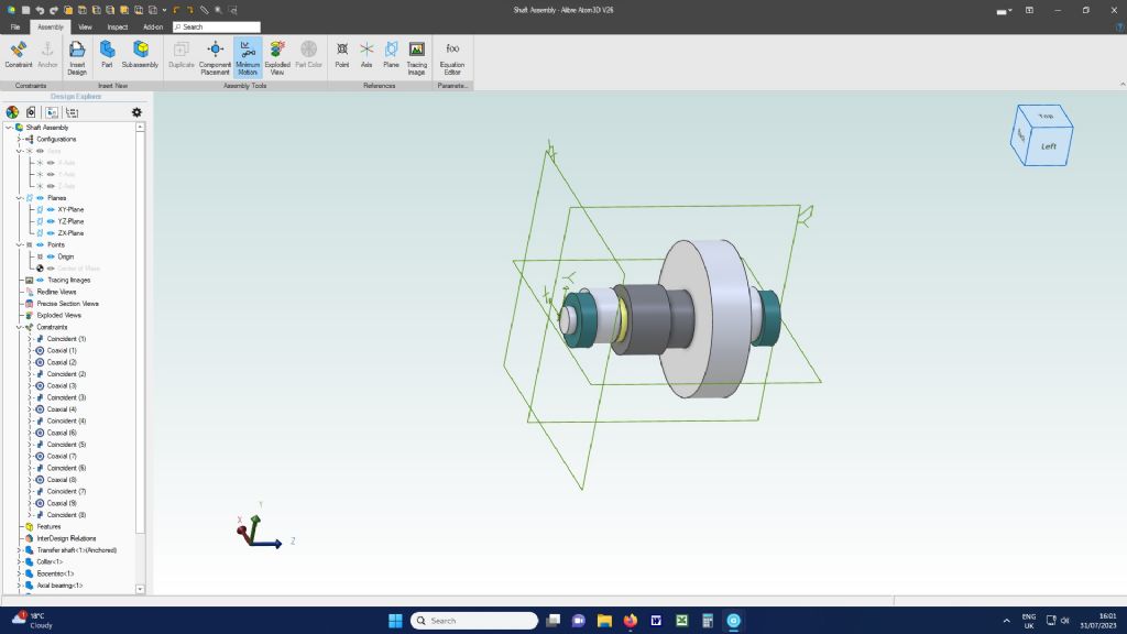
      This gear-shaft assembly was the subject of my previous thread.

      It is effectively the back part of a back-gear type reduction drive using 4 gears I have , but represented here by their pitch cylinders. Originally the spigot on the smaller was to nest in a counterbore in the larger but that proved too hard to draw.

      Somehow 6 holes for screws to lock them together, drilled through the larger wheel, have vanished too.

      I miscalculated the length of the shaft. It should be the length of the rest. I could no find no way to shorten it except by re-drawing it; but that just seemed to keep running into trouble. Lesson One: make a dimensioned paper and pencil sketch first!

      Along the shaft there are: retaining collar, eccentric, an axial bearing washer, the two gears (their bearing bushes hidden), second axial washer, eccentric, collar.

      I have omitted finer details like the collar's grub-screws.

      Placing the eccentrics proved odd. I found it very hard to put in the grub-screw hole (just as plain hole); and that it worked was more luck than judgement. When placed on the shaft the first was aligned to the plane but its copy rotated itself by some random angle near 90º relatively to the first. That Component Placement tool would not act on it, and I had to pull it round into line by very tentative dragging until it looked right. If I actually make this thing I will mill seatings for the grub-screws so the eccentrics are in line. (I have no tooling for cutting internal key-ways with any certainty.)

      shaft assembly.jpg

      Advert
      #21431
      Nigel Graham 2
      Participant
        @nigelgraham2
        #654496
        Ady1
        Participant
          @ady1

          Is it the assembly or a drawing

          You have deleted every possible piece of useful information to post that jpg

          drummond.jpg


          Edited By Ady1 on 30/07/2023 23:11:32

          #654499
          Ady1
          Participant
            @ady1

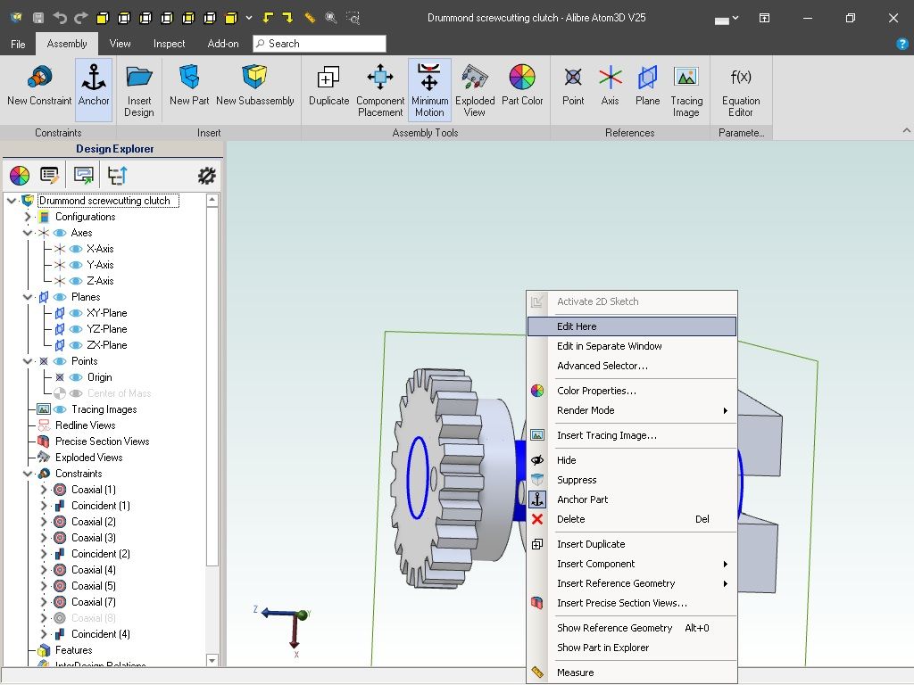
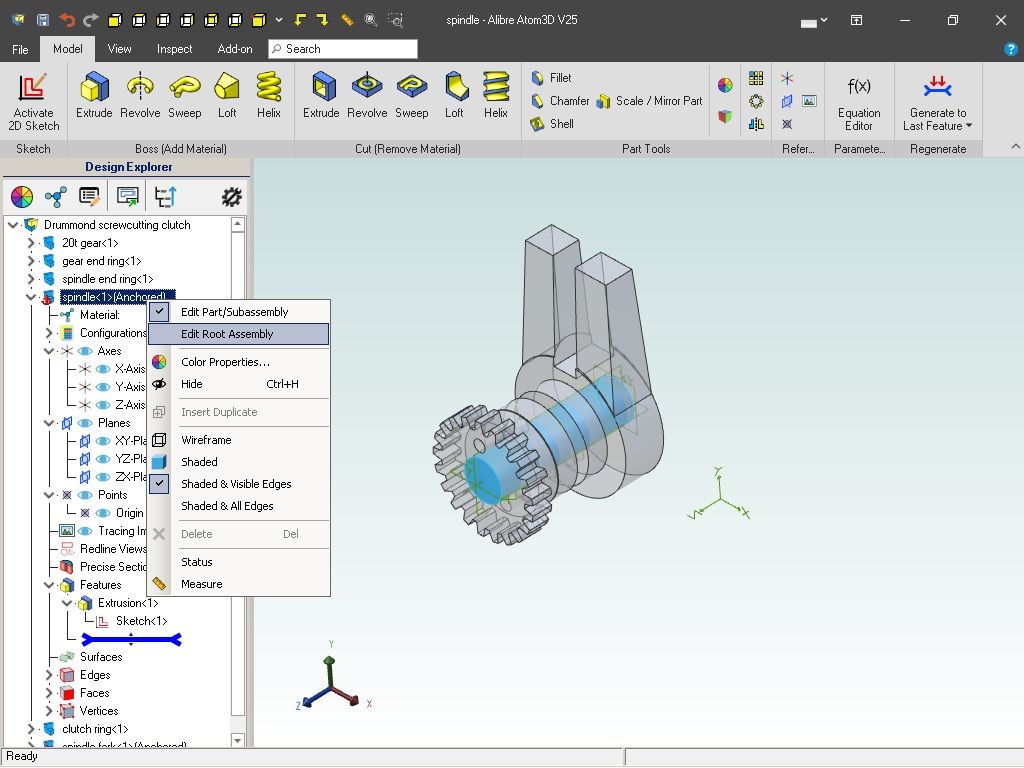
            If we assume assembly you can either redo the shaft in the original drawing or edit it in situ

            Editing the shaft in situ

            assembly edit 1.jpg

            The assembly editor is a bit of a pain because it splits the main bits we need

            assembly edit 2.jpg

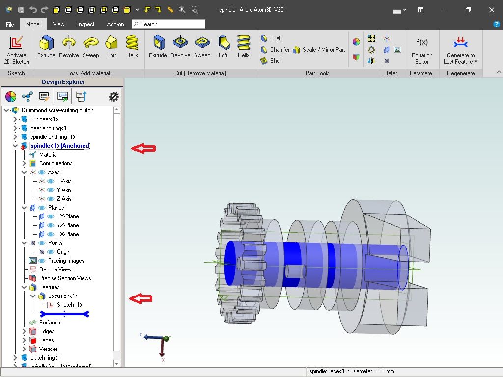
            Then right-click edit the shaft sketch or extrusion

            To go back to assembly click on root assembly

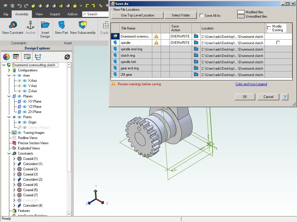
            assembly edit 3.jpg

            When you go to save it shows you the spindle update you did as an over write

            assembly edit 4.jpg


            Edited By Ady1 on 30/07/2023 23:50:00

            #654500
            Ady1
            Participant
              @ady1

              I tend to use the long route to reduce the chance of a pooter crash with bigger assemblies, there can be an awful lot going on and I get nervous

              Shut down the assembly,

              edit the original sketch/extrusion part.

              re-open the assembly

              I also do periodic backups of the assembly (assemblybak)

              RE: your missing holes

              If you go back to the original part you may find it has not been regenerated to the final feature and the holes are actually still there. Alibre drawings will save without all the features re-generated after an edit… argh

              Yet another Alibre sneaky to watch for, been caught by that one a few times when I get absorbed with a project

              (There may be a tick box option somewhere that forces 100% regeneration upon saving a file)

              Edited By Ady1 on 30/07/2023 23:59:17

              #654501
              Ady1
              Participant
                @ady1

                If you're still struggling with constraints just play with 2 and 3 part assemblies as you would with lego

                An awful lot of the learning process is experimenting and manipulating bits until you start getting the bigger picture

                Going straight into a defined project is the hardest learning route imaginable, you must be comfortable with the basics first

                #654502
                Ady1
                Participant
                  @ady1

                  and don't worry about having red bits like constraint issues or the like when you post up your work

                  These things give us clues as to what pointers will work best to get you going on the path to nirvana

                  You've put a lot of time in to getting this far

                  #654505
                  JasonB
                  Moderator
                    @jasonb
                    Posted by Nigel Graham 2 on 30/07/2023 22:34:07:

                    Somehow 6 holes for screws to lock them together, drilled through the larger wheel, have vanished too.

                    Either you deleted them from the part or more likely you have edited another item up the tree on the left of the page and neglected to click "Generate to last" so the features after where you last edited are not showing

                    I miscalculated the length of the shaft. It should be the length of the rest. I could no find no way to shorten it except by re-drawing it; but that just seemed to keep running into trouble. Lesson One: make a dimensioned paper and pencil sketch first!

                    No need to redraw, just open up the part file again and right click on the extrusion operation where you entered the length which will open up the extrude dialogue box again and you can simply enter a revised length.

                    Along the shaft there are: retaining collar, eccentric, an axial bearing washer, the two gears (their bearing bushes hidden), second axial washer, eccentric, collar.

                    I have omitted finer details like the collar's grub-screws.

                    Placing the eccentrics proved odd. I found it very hard to put in the grub-screw hole (just as plain hole); and that it worked was more luck than judgement. When placed on the shaft the first was aligned to the plane but its copy rotated itself by some random angle near 90º relatively to the first. That Component Placement tool would not act on it, and I had to pull it round into line by very tentative dragging until it looked right. If I actually make this thing I will mill seatings for the grub-screws so the eccentrics are in line. (I have no tooling for cutting internal key-ways with any certainty.)

                    I've covered this in one of your previous posts, if in the assembly window you right click while the cursor is over the component and click "show reference geometry" that will show the three planes and axis of the given part. You can now set one of the planes relative to the main planes or that of another part be they coincident or at an angle to each other

                    #654517
                    Nigel Graham 2
                    Participant
                      @nigelgraham2

                      Thankyou.

                      It's actually simpler than the tutorials on the Atom Alibre web-site! Although based on investigating how to drive a small milling-machine needing a 20:1 speed reduction from motor to spindle; as a CAD exercise it should be basic. I omitted difficulties like the end-collars' grub-screws, and the operating-handle. I could have used parts from published drawings, to practice with, but they are no simpler.

                      As an engineering exercise it proved interesting: I have used lathes with back-gears for many years but never really quite knew how they work!

                      As a CAD assembly though, that drawing is merely four pairs of cylinders strung on one long cylinder.

                      The eccentrics are the only complicated part. I did not deliberately remove the ring of pin holes in the larger gear. They vanished when I did something else to it.

                      Drawing the accompanying drive-shaft with fast-and-loose gear and pulleys would be far, far harder; the complete gear-frame, beyond me. My practical approach would be to make the moving parts then work out how to build a frame to hold and connect them.

                      It would be impossible to draw the entire system, motor and all. I would not even think about trying it, even with the milling-machine reduced to a symbolic rectangular frame holding the spindle with its pulley. (The machine, made for line-shaft drive, has the spindle inside an open, one-piece cast-iron frame whose top member holds the single over-arm.)

                      .

                      I realised where I'd gone wrong with the shaft length. I had miscalculated the length of the stack of parts initially when I drew the shaft. Later, I found that "Measure" tool to discover the real length; but then mis-quoted that in turn in re-drawing the shaft. I tried to find how to edit its length but found only how to change its diameter.

                      .

                      Ady –

                      I was saving the drawing as I went along, so as not to lose everything.

                      The only way to post a CAD drawing here is as a jpg file, so naturally not holding the information you mention.

                      I know it's possible to copy an image of the screen, which may be what you mean, but I have never been clear how to do that. It's not obvious where you even find the command.

                      #654521
                      Nick Wheeler
                      Participant
                        @nickwheeler

                        Your 'practical' way of building it is exactly how you would design it in CAD – assemble the parts so they work, and build brackets/case around them using the relevant features(axes, mounting faces, bearing diameters etc) of the parts themselves.

                        Altering the length of the shaft would have been easier using a command to 'extend it to this feature' instead of you calculating how much it needed to be changed. Then when you need to move stuff around again, it will remain the required length.

                        I agree that a quick paper sketch before you started is a good idea, but it's to clarify your thoughts for the assembly – the wotsit must go here, but it turns the thingy so the side-fumbling dinglearm self reciprocates, so where can the output shaft end up? – NOT design the dimensions.

                        #654522
                        Ady1
                        Participant
                          @ady1

                          It's the keyboard command near HOME

                          PrintScreenSysRq

                          Then paste it into paint and save-as a jpg

                          I tend to put them in my downloads folder since it already gets used by my browser

                          #654526
                          Ady1
                          Participant
                            @ady1

                            If you're getting more confident we need to do a few Model Engineer scale drawings

                            Nothing fancy, just homework type stuff to build confidence

                            There's a relatively simple plan here that is available to all

                            https://www.model-engineer.co.uk/news/article/free-plan-cross-vice-to-vertical-slide/22255

                            name a separate folder

                            create a master-imperial PART file (I use 64ths but 1/16ths will do most bits)

                            Draw up the parts apart from the acme thread, just make that part as a shaft

                            I'll do the same thing

                            Don't do any threads, just shafts and holes

                            Do each part in its own file (from the master imperial) and name it like it is in the plan

                            They all get dumped into assembly once they've been drawn

                            This exercise forces us to be disciplined and logical, there's no short cuts during the familiarisation process and being happy with drawing out plans is an essential step

                            And start your file with the easy parts, don't start with the awkward ones

                            Edited By Ady1 on 31/07/2023 10:23:36

                            #654567
                            Nigel Graham 2
                            Participant
                              @nigelgraham2

                              Nick

                              Sorry, I'm not clear what you mean about not design the dimensions. Surely you need know how big to make the parts before you can draw them? Besides, the central parts of this thing are two stock gears, so they dictated the rest. I'd gone wrong by not noting how big each bit is, first, then by not knowing how to dimension each part, then mis-calculating and mis-quoting the shaft length later.

                              .

                              Ady

                              What you suggest as exercises was more or less as I thought of doing. I was considering some of the parts on the drawings for a 'Stent' T&C Grinder, but other than the odd spacer or two, they all seemed a lot harder than the "string of beads" that I eventually tried.

                              I did draw everything as individual part files, and had thought its assembly would be very simple as it is just a string of those simple cylinders with holes through them, around a plain bar. No gear teeth, driving-pins, keys, grub-screws etc.

                              If I can't grasp doing that, I may as well give up.

                              .

                              One of Alibre's own tutorials – or was it that scribing-block? – does have you draw a thread, and yes it is a right awkward operation. As was the scribing-block's taper. All right if you need design the thread or want a very realistic image, but that's all. I've forgotten how, beyond the last move being the cut tool itself.

                              Edited By Nigel Graham 2 on 31/07/2023 15:59:16

                              #654572
                              Nigel Graham 2
                              Participant
                                @nigelgraham2

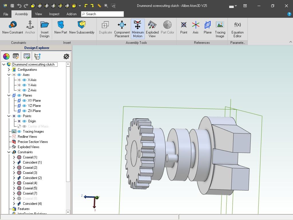
                                Have now managed to shorten the shaft to its right length (near enough) and to take that screen-shot – once I found where "paint" was hiding.

                                alibre screen image.jpg

                                #654625
                                Nealeb
                                Participant
                                  @nealeb
                                  Posted by Nigel Graham 2 on 31/07/2023 15:56:54:

                                  Nick

                                  Sorry, I'm not clear what you mean about not design the dimensions. Surely you need know how big to make the parts before you can draw them?

                                  I think that you might be missing one of the great features of the kind of 3D parametric CAD we are talking about here. You are in excellent company – I have done a certain amount of tutoring in 3D CAD and have always had the biggest problem working with very experienced draughtsmen/designers coming from a 2D background. There are certain principles you learn in 2D that are better forgotten when working in 3D. One of the mantras that I tell people is "never use a dimension if you can use a constraint." Like all such things, it is not an absolute hard-and-fast rule but it's always worth considering.

                                  In this case (and I'm simplifying the geometry a bit) let's say you want two gears that the supplier's catalogue gives as 6.35mm thick. You want a shaft through them that sticks out by 10mm either side. So, I would model the two gears (as plain cylinders based on their pitch circle, quite possibly) and assemble them in their correct relative positions. For the shaft, I draw a circle on the outer face of one gear, then extrude that by the design dimension of 10mm from that face. I then extrude the same circle in the opposite direction using a constraint so that it finishes 10mm from the outer face of the other gear. Net result – a shaft that exactly matches my design goal. At no point do I calculate the length of the shaft – I shall find that later from the manufacturing drawing that my software produces. A variation might be that the gears sit on a shaft that runs between bearings in a fixed position, and you need a spacer to suit. In this case, the spacer is constrained to have one face on the face of one gear, and the other to be some clearance dimension short of the face of the bearing. I never need to actually calculate the spacer length.

                                  Why do it this way? Couple of reasons: one is that coupling individual parts together in this way is likely to lead to fewer drawing errors. If you have tied the parts together like this then you can't accidentally draw them with different dimensions. A second reason is that by implementing the design in terms of "design goals" rather than calculating dependent dimensions and hard-coding them into the model, it is much easier when things change. In this case, what if your supplier actually says, "Sorry – no 6.35mm thick gears; they are now 6mm." You go to your drawing, change two dimensions (gear thicknesses) and everything that depends on these dimensions automatically gets updated. This actually did happen to me when I was designing my CNC router. A hole spacing in one bracket depended on the combined thickness of several other components. I had designed this around the 50x12mm bar I had ordered, only to be told that the supplier only had imperial dimension bar – 2"x1/2". So I changed the bar thickness from 12mm to 1/2" in the model and reprinted the bracket drawing. Job done. Actually, one of the biggest gripes I had with TurboCAD which I used to use regularly was that it was so difficult to make these kinds of changes without scrapping the whole drawing and starting again. 3D CAD came as such a breath of fresh air.

                                  So, in response to your comment – not only can you draw parts of your assembly without knowing in advance their dimensions, but very often you should!

                                  Edited By Nealeb on 31/07/2023 22:13:10

                                  #654633
                                  Nigel Graham 2
                                  Participant
                                    @nigelgraham2

                                    Nick –

                                    I'm still confused!

                                    So you'd put your two gears together then draw the shaft "through" them with the right amount protruding at the far end? You still need some idea of sizes, such as the gear's thicknesses, and the protrusion – even if you do then find the manufacturer's gone and made them thinner.

                                    I know changing a Part in its own drawing automatically up-dates it in an Assembly that's already used it; and an extremely useful feature of Alibre that is. However, in your example having thinned the gears, won't the shaft now protrude 10.7mm from the gear face? Or does having Constrained it at 10.0mm in the first place automatically shrink it to maintain that 10.0mm when you make the wheels thinner?

                                    Does that shaft you've drawn as an extrusion though two existing parts "exist" as a third part in its own right, or would removing either of two gears leave a rather peculiar space or a 10mm thick disc floating in fresh air?

                                    .

                                    I abandoned TurboCAD's 3D mode, and kept to its 2D mode, but I don't recall drastically re-drawing the whole thing to change one part. Modifying the associated components yes, because TC does not work by parts and assemblies (though an expert user might be able to drive it that way), and it lacks Alibre's facility to carry changes through. Well, it might now, I don't know; but likely only in the advanced 3D realms of its latest editions.

                                    .

                                    Ady –

                                    I've just looked at that vertical-slide drawing set you cited…..

                                    Thank-you, but that would be far too advanced for me, certainly at the moment.

                                    I might manage one or two of its simplest bits but if I struggle to create 8 simple cylinders and string them along a rod, I'm not going to cope with something as difficult as that project.  

                                    Edited By Nigel Graham 2 on 01/08/2023 00:00:39

                                    #654636
                                    Ady1
                                    Participant
                                      @ady1

                                      That's ok Nigel I've got plenty to keep me going atm

                                      The picture you posted looks fine btw

                                      When you feel more ready then kick off a thread and I'll join you in doing it

                                      some bits in the plan I'm not so sure about but the way it works is you just keep plugging in the parts and the eureka stuff happens as it comes together

                                      As for yourself just keep doing the lego stuff until you want to do simple plans, and its at that point that your wheels start leaving the runway tarmac behind

                                      Edited By Ady1 on 01/08/2023 00:38:24

                                      #654649
                                      JasonB
                                      Moderator
                                        @jasonb

                                        At Nigel's stage of the learning curve I think it is probably better that he does as th etutorials show and draw each individual part a s aseparate file and then bring them together in an assembly.

                                        Nigelo do what is being suggested by Nick and Nealeb requires a new part to be drawn from an assembly so that certain dimensions are constrained to parts already in the assembly.

                                        Take your example and lets say start with one of the gears, draw that as a part and save. You would then need to create a new assembly and place that gear in it as your first part. Next click the "new part" tab at the top of the assembly screen and instead of drawing on a blank screen you will be drawing on a screen that already shows the gear but transparent. Lets say you want to draw the shaft next so select the plane and draw a circle which you can set concentric to the hole in the gear, close 2D and now extrude the shaft but rather than just entering a length you can select geometry which would be one side of the gear and offset 10mm from that.

                                        You now have a shaft that sticks out 10mm from the edge of the gear. If you subsequently decide your initial 12mm wide gear was too thick and want to change it to 6mm you can edit the 12mm extrusion to 6mm which will make the gear narrower.

                                        Now when you open the assembly again the gear will be it's narrower 6mm but the shaft will still be sticking out 10mm from the edge, any 2D drawing produced or measurement taken from the screen will show the reduced length of the shaft you have not had to calculate it's revised length and there is no need to go back and edit the shaft to reflect edits to the gear

                                        Had you done it as two separate parts then the shafts length would not have changed when the gear was made narrower so depending on where it was placed will end up with a different stickout and no change in length.

                                        #654671
                                        Nigel Graham 2
                                        Participant
                                          @nigelgraham2

                                          Well, presumably both approaches still need you know the eventual outcome.

                                          Thank-you for explaining that way – it seems based on starting from the primary components of the assembly then building the rest around those more or less as they dictate. So on a reduction-gear, starting with the gears then forming the shafts etc. to suit them. Well, gears then bearings perhaps. I can see the logic of that.

                                          Yes, the introductions assume knowing all the shapes and sizes at the start, but though that might make learning the programme easier, for a real project you would need almost design the thing in some detail before you can draw it. The people who write the tutorials have already done that for you; and if the same reduction-gear was one of their exercises you could draw its parts in any order.

                                          That original MEW exercise, the scribing-block, was in a logical manufacturing order but that also suited the point of the exercise itself (learning the basics of Alibre) by putting the simplest parts first.

                                          .

                                          If you went on to make the scribing-block that's your own bonus, but with a full set of drawings the parts-making order does not matter!

                                          #654689
                                          Nick Wheeler
                                          Participant
                                            @nickwheeler

                                            You are emphasising details like most of the dimensions too early in the design process. You'll start with a few basic dimensions – in this case the gears – and the need for other pieces, then build the rest around them just like you will when you've made the physical parts. It makes sense to me to define those dimensions as editable parameters from the start, which also aids in thinking about the design. A back of an envelope sketch is often good enough for this, which is no different to how you would have done the job with 2D drawings on paper. That sketch can also be done in CAD…

                                            As Neal said, you don't need to determine dimensions of many of the other parts, but just define where and how they fit. That's because the dimensions, drawings, or most of the other processes are just steps along the way to having an actual part that does what you want – you don't get in your car and obsess about whether the piston diameters match the designer's original drawings do you?

                                            I don't design assemblies as separate parts brought into a final file, but keep them all together. That's partly because the free version of Fusion only allows for 10 editable files at a time and you can't edit external files in place. It's also so much easier to see how your crankshaft fits into the crankcase and aligns with the bores as an example.

                                            #654756
                                            Nigel Graham 2
                                            Participant
                                              @nigelgraham2

                                              Just tried it as I think you mean….

                                              I made a new Assembly, stuck my two gears together, using them simply because they already exist. then gave them a short shaft in situ. Too short for any real machine-part but that was not the point.

                                              I could make it start from one face and protrude 5mm from the far face, but could not find how you would make it stick out of both faces. I tried that "dual" geometry choice but that just stuck two 5mm "discs" to the starting end.

                                              #654774
                                              JasonB
                                              Moderator
                                                @jasonb
                                                Posted by Nigel Graham 2 on 01/08/2023 21:54:06:

                                                I could make it start from one face and protrude 5mm from the far face, but could not find how you would make it stick out of both faces. I tried that "dual" geometry choice but that just stuck two 5mm "discs" to the starting end.

                                                Two options there. lets assume you wanted 5mm projection each side.

                                                1. When you create your new part first thing to do would be create a new plane 5mm from the side of gear A. Next draw your circle on that plane. Then extrude that circle and use "to geometry" selecting the far side of gear be as the target geometry and add a 5mm offset.

                                                2. Create the shaft as two end to end cylinders. Draw a circle and extrude to geometry of gear A with 5mm offset. Then draw the same dia circle again but extrude to gear B again with the 5mm offset

                                                #654794
                                                Anonymous

                                                  I am flummoxed by the idea of creating a part in an assembly, ie, the shaft in an assembly of gears. How does one then create a 2D drawing of the shaft that doesn't exist as a seperate part?

                                                  I prefer to create seperate parts, that represent the parts I wlll actually make. When creating a part I don't sweat over dimensions initially. Just create all the features I need to create a part that is topologically correct. I can then go back and add dimensions.

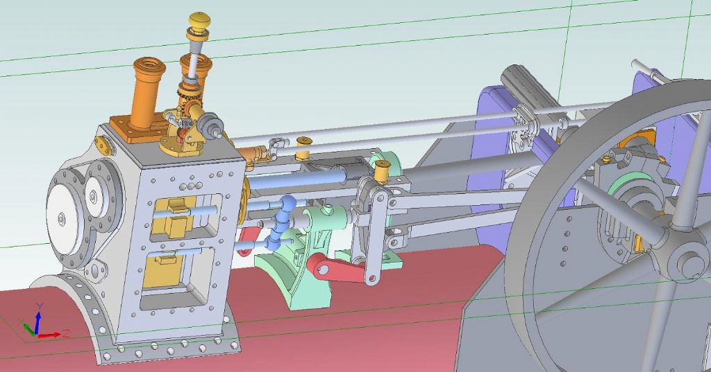
                                                  Assemblies are created from individual parts, using constrains as needed. Just as one would build the physical item. I only use constraints that are strictly necessary. Not only is an assembly used to make sure holes in mating parts line up for instance, it is also used to make sure that parts fit together and move correctly when the assembled parts move, as they would in reality. Like this assembly of the motion work on my traction engines:

                                                  motion work assembly.jpg

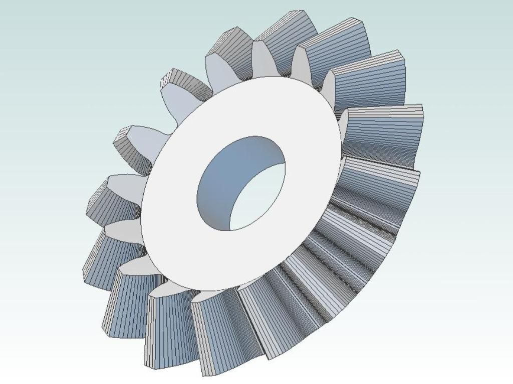
                                                  I tend to design gears complete with accurate tooth forms. Here is a bevel gear model:

                                                  complete bevel.jpg

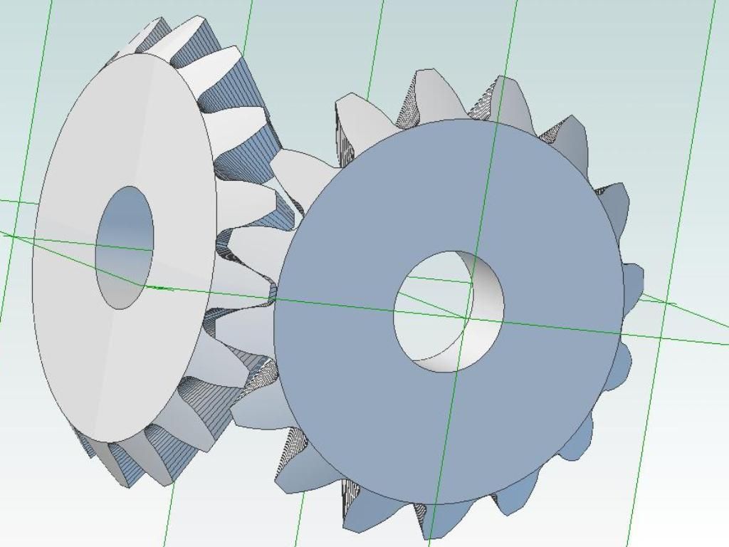
                                                  An assembly to check meshing:

                                                  assembly.jpg

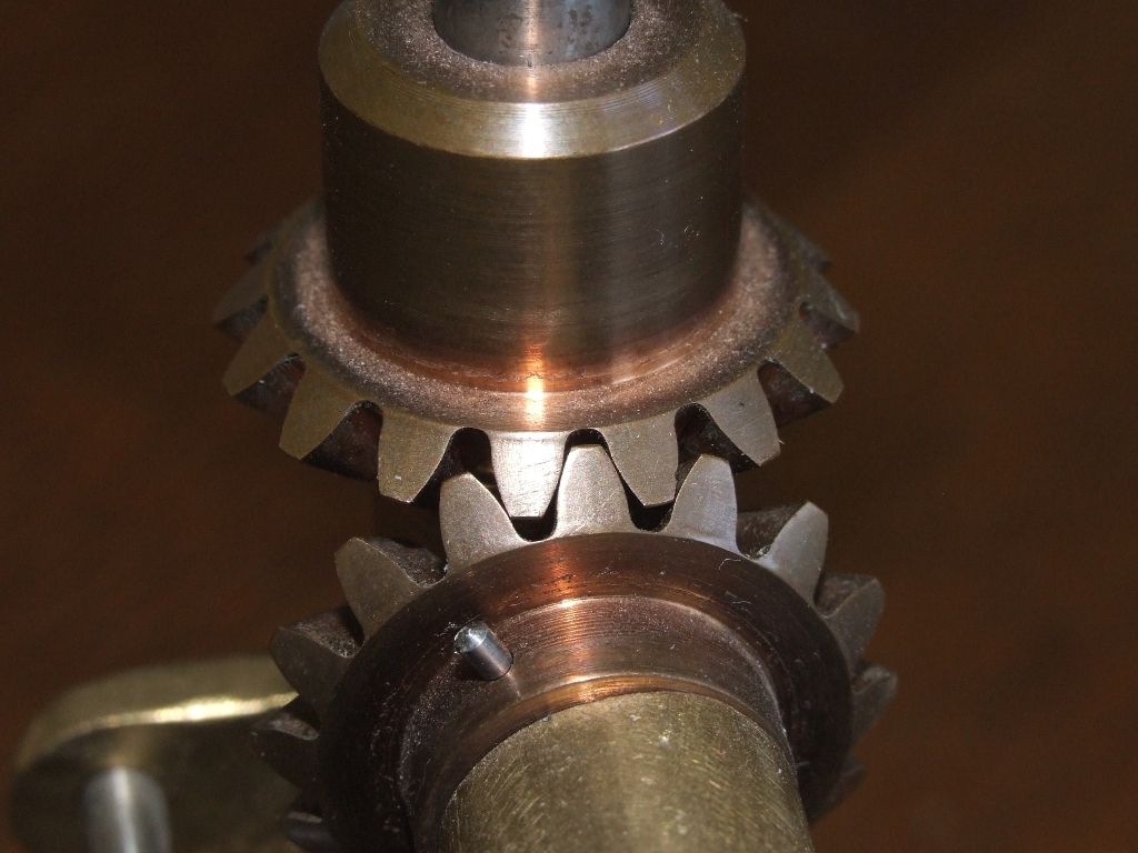
                                                  And reality after CNC machining:

                                                  bevels_me.jpg

                                                  The bevel gear PCD is 1" at the outer end.

                                                  Andrew

                                                  #654800
                                                  Ady1
                                                  Participant
                                                    @ady1

                                                    Alibre Atom is for basic CAD work on a basic computer, my own unit is a 2008 Windows 7 unit

                                                    Total cost 250, plus 50 for a decent graphics card

                                                    Are you by any remote chance showing us what £2000 of CAD on a workstation costing thousands can do?

                                                    Just one of those bevel gears would have my poor computer stuttering to keep up

                                                    #654801
                                                    JasonB
                                                    Moderator
                                                      @jasonb

                                                      Andrew, the shaft does exist as a separate part.

                                                      If you read my description when in the assembly screen you click "new part" which is next to insert design that you would usually use to bring in separate parts.

                                                      You will then find you have the usual screen you would be using to model a separate part but also have the assembly "greyed out" so you just carry on drawing your new part but can make use of any other features of the assembly as reference points. When you then go to save you get a box come up that allows you to name your new part EG "gear shaft" and that will be stored just like a part created individually so 2D drawing easy to produce in exactly the same way.

                                                      For example I could do the steam chest cover as my new part, making it's edges co-linear to the sides of the cylinder and using the stud hole pattern of the cylinder to position the clearance holes. Now the god bit is that if at some time you alter the cylinders O/A size or the stud positions then the cover will automatically get updated

                                                    Viewing 25 posts - 1 through 25 (of 56 total)
                                                    • Please log in to reply to this topic. Registering is free and easy using the links on the menu at the top of this page.

                                                    Advert

                                                    Latest Replies

                                                    Viewing 25 topics - 1 through 25 (of 25 total)
                                                    Viewing 25 topics - 1 through 25 (of 25 total)

                                                    View full reply list.

                                                    Advert

                                                    Newsletter Sign-up