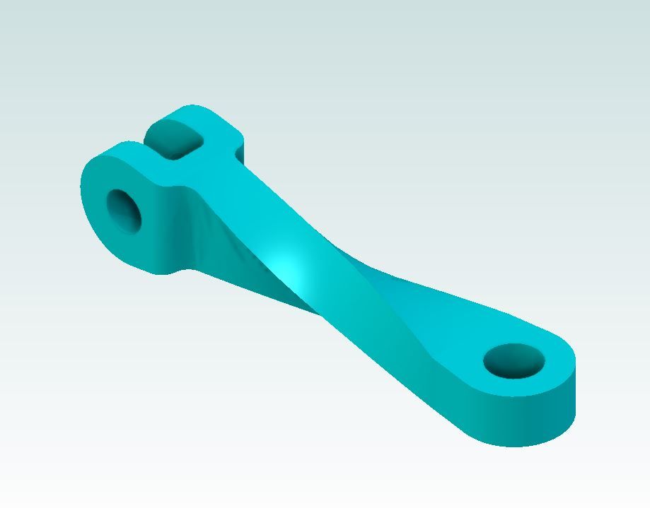
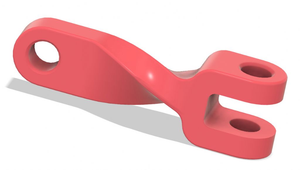
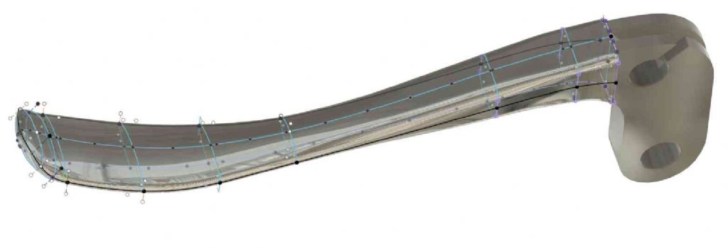
Not being familiar with MOI, I could understand what you were doing it it was done! I don't know if I could replicate that in DesignSpark or SolidEdge. Very elegant.
Very interesting Eddie. I think I could do most of that in SE and (to my mind) some aspects of using SE seem easier than how you did it using MOI (from a UI perspective) but as always with CAD, I believe that "you like what you know". The operation I haven't tried to do in SE was the 'twisting' at the end. I'm pretty sure SE can do something similar but is let down by its User's current level of expertise (or lack thereof)
As an aside, I started playing with variable tables in SE yesterday and found that I could set up simple objects that were somewhat like Open SCAD models, where you just change key named variables and the whole model is updated immediately. I don't have an immediate use for them but did enjoy exploring the basics…
I've put the knowledge in my "May Come in Useful Later " box for now
The twist, which I expected to be the hard part, is easy. Rounding is usually trivial in SE but not this example! I can't get the tool to follow the edges all the way round. Might be doing it wrong – there's a bunch of settings I haven't tried, and don't understand.
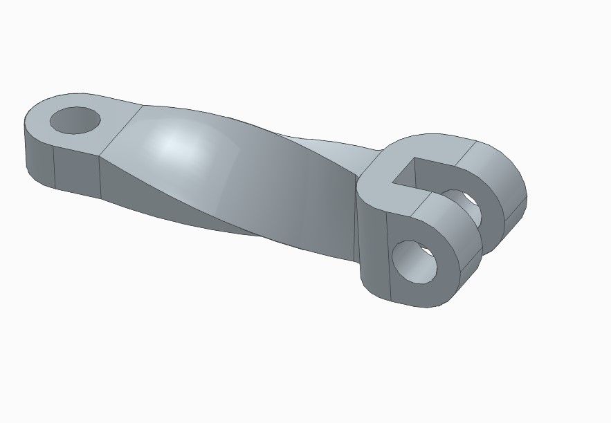
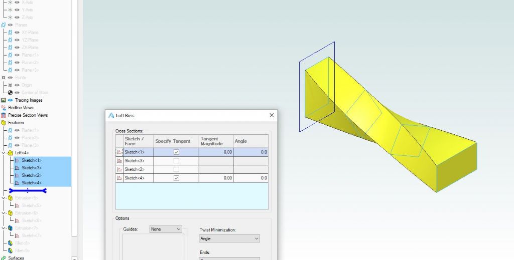
Gary and Dave look to have taken the easy route with a straight ctr section rather than the dogbone that Martin and I have done with the 125mm radius which did need quite a bit more work in Alibre than MOI to get it to twist than a straight section would
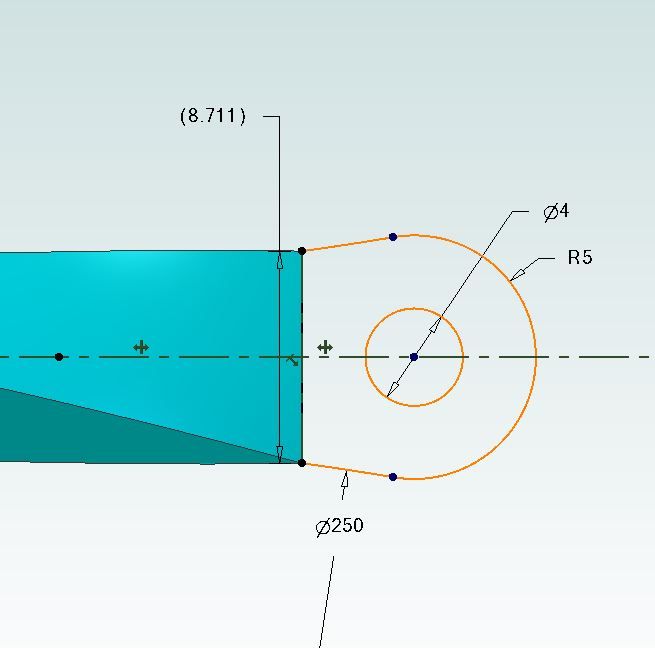
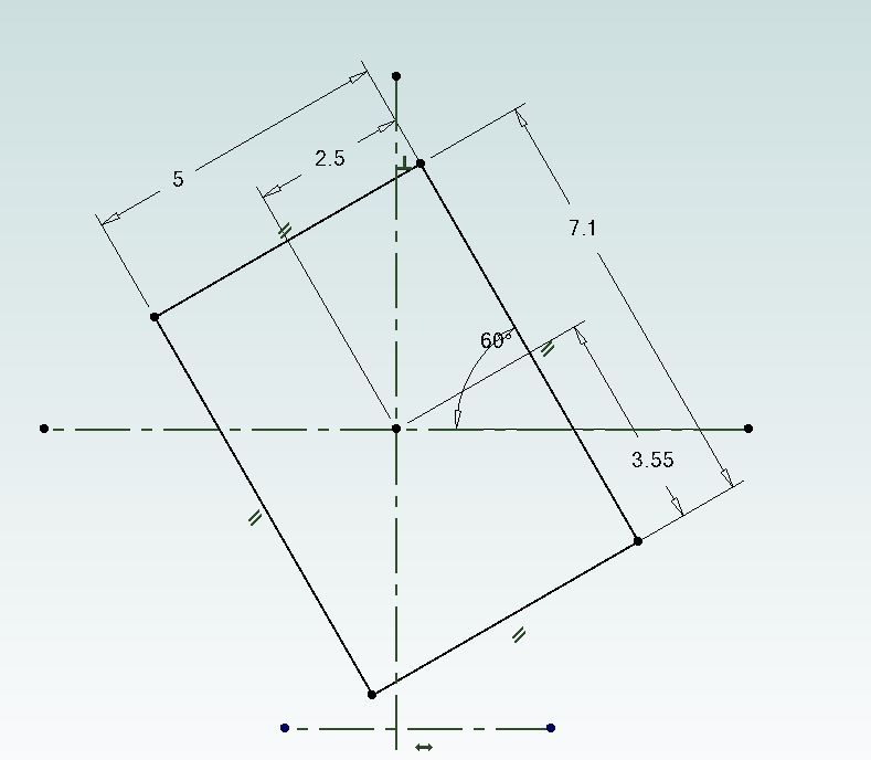
I used loft as could not seem to do the dogbone shape with anything else, that was the long winded bit as I needed to loft 4 rectangles and pick up their lengths from a 2D sketch. My Ends are 10mm dia and you can see from these sketches that I had to use various sizes to form the rectangles to loft, the 5mm thickness is constant
The CAD twist function is fantastic, but why would you need to manufacture this item with a twist – would that be stronger than simply designing it so the shaft with the single eye was kept straight but attached to the U piece 90° further round ?
You're right, nobody would machine a part all over and then twist it for the other end.
But a link that only needs a drilled hole at each end at 90° makes perfect sense made from a length of twisted bar. Which would be modelled like these were. I must have a go when I've finished my roof-bar ladder clamps. And done the welding on the Metro.
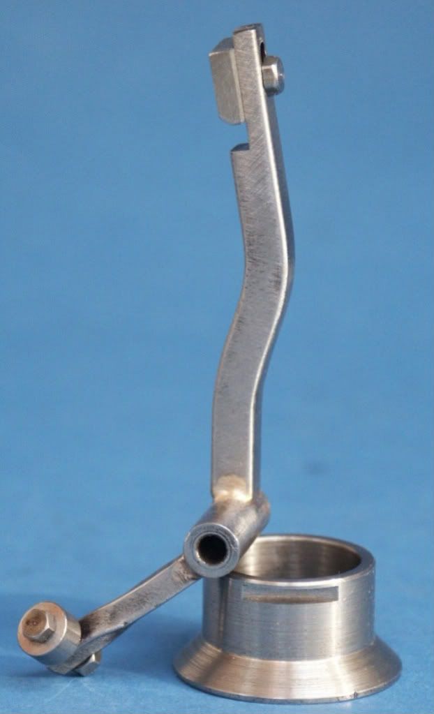
Really, I've twisted several parts for models, no doubt the blacksmith who made the full size many years ago would have done the same. How would you model the lower arm on this part?
As for the clevis just because the twist was put in at the design stage does not mean it needs to be done as part of making it. Could be lost wax cast or metal printed or maybe it is for an injection moulded plastic part.
Gary and Dave look to have taken the easy route with a straight ctr section rather than the dogbone that Martin and I have done with the 125mm radius which did need quite a bit more work in Alibre than MOI to get it to twist than a straight section would
It's a fair cop guv'. The easy route is also possible in FreeCAD. I haven't tried to twist a dog-bone yet.
MOI seems particularly good at twist operations. I can see why blowlamp likes it. For my purposes Assembly is more useful than twisting, despite Chubby Checker…
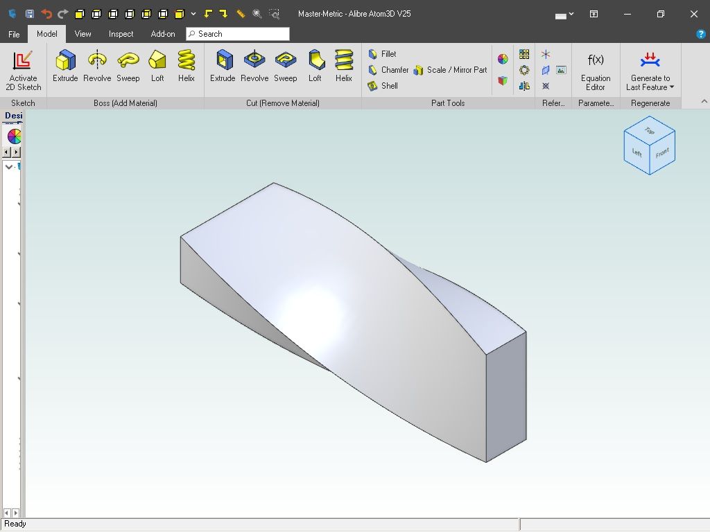
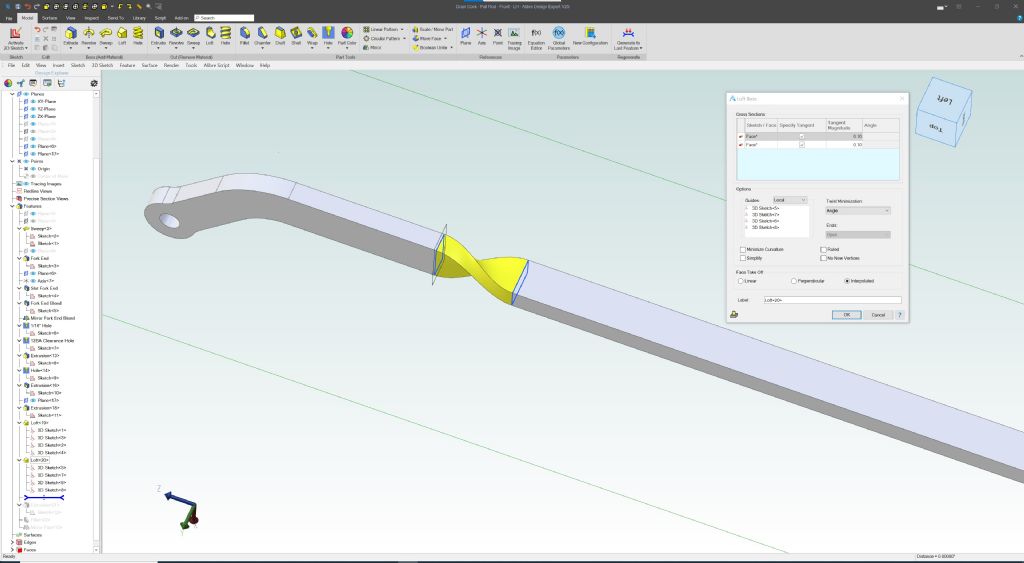
Another method in Alibre, is to Loft using two rectangles and four 3D Guide curves (straight lines in this case). These guide curves connect each corner (Vertex ?) of the first rectangle, to the corresponding twisted corner on the second rectangle.
Note that this may not work in versions earlier than V25.
As an aside, I started playing with variable tables in SE yesterday and found that I could set up simple objects that were somewhat like Open SCAD models, where you just change key named variables and the whole model is updated immediately. I don't have an immediate use for them but did enjoy exploring the basics…
I've put the knowledge in my "May Come in Useful Later " box for now
Ian,
The variable table is very useful, you can also relate driven dimensions to other dimensions by entering equations in the formula column. As you have found, the model then updates immediately as you edit the table. However, you need to take care with driven and driving dimensions and which end(s) of the dimension are driven otherwise the model may distort unexpectedly. Care also needs to be taken where other features may be dimensioned from the edited feature.
The variable table really comes to the fore when you start using one of the key features of solid edge, the Family of Parts feature. A master part is created, this can include both Synchronous and Ordered features. In SE 2023, Ordered features are shown as outlines in Synchronous mode when viewing in shaded style but appear normally in wire frame style.
If not visible, the Family of parts feature is entered by selecting the Family of Parts pane from the Panes tab of the view menu. The Master part becomes the basis of a family of related parts, created by adding new members to the family and editing the new members in the variable table. Any ordered features in the table can be suppressed so it is possible to create parts with or without all of the features of the master part.