My Lunkenheimer Carburetor 3D modeling attempt

Advert

My Lunkenheimer Carburetor 3D modeling attempt

Home Forums CAD – Technical drawing & design My Lunkenheimer Carburetor 3D modeling attempt

Viewing 21 posts - 1 through 21 (of 21 total)
  • Author
    Posts
  • #597782
    PatJ
    Participant
      @patj87806

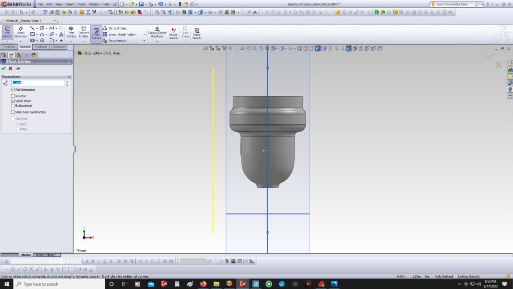
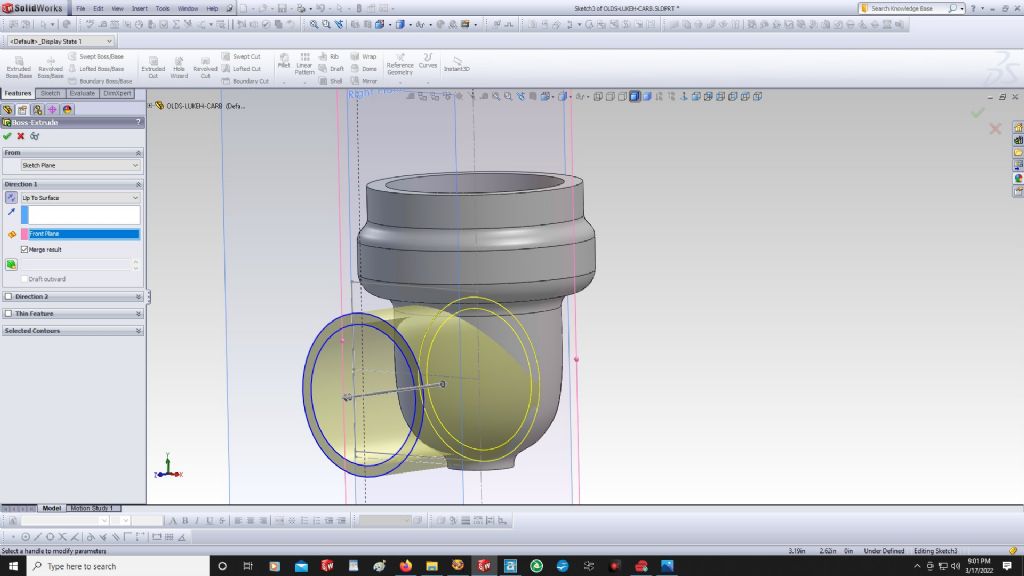
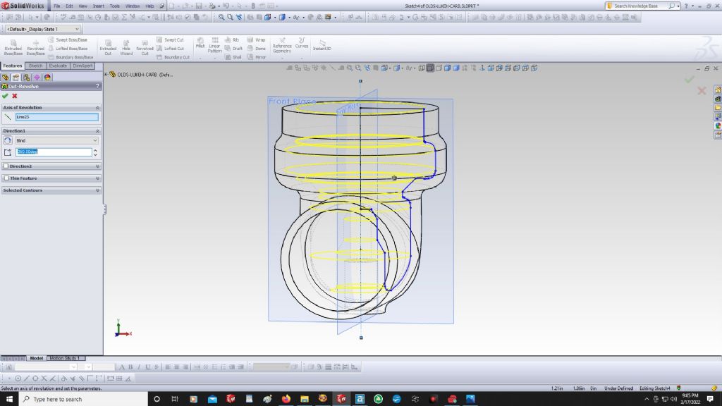
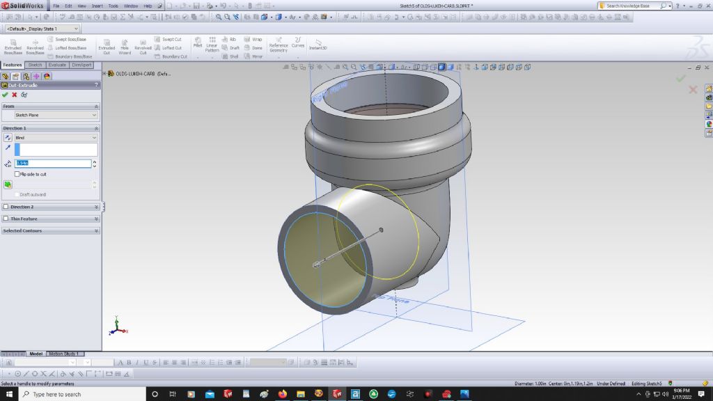
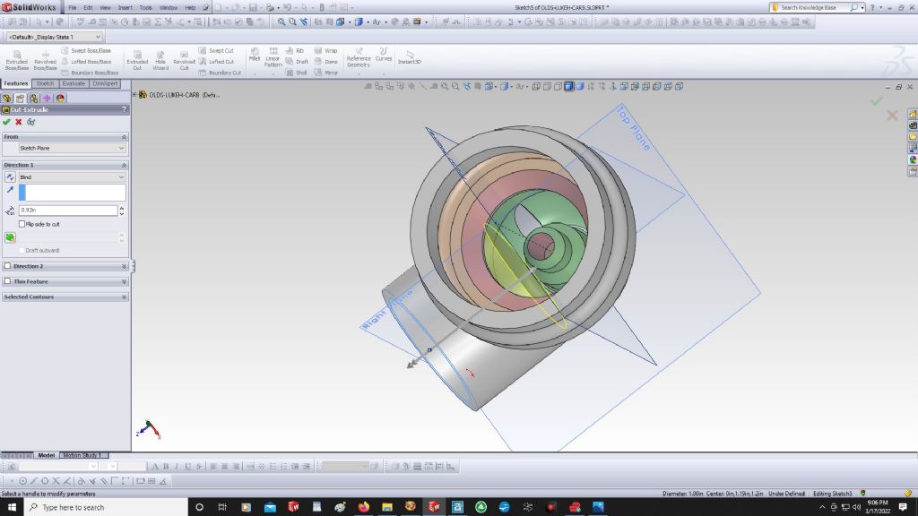
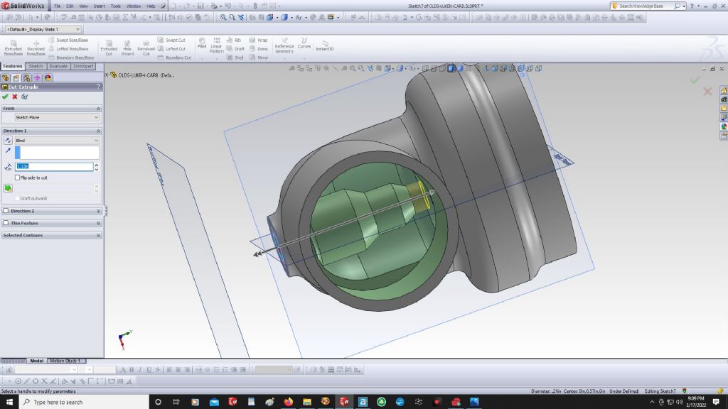
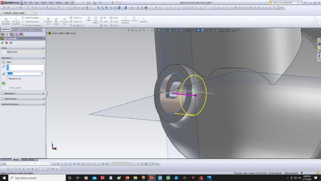
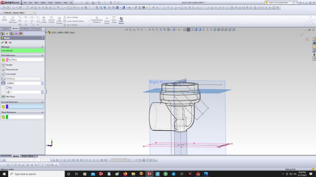
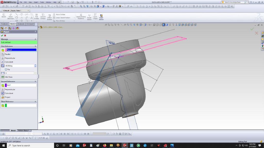
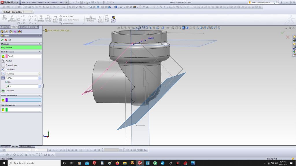
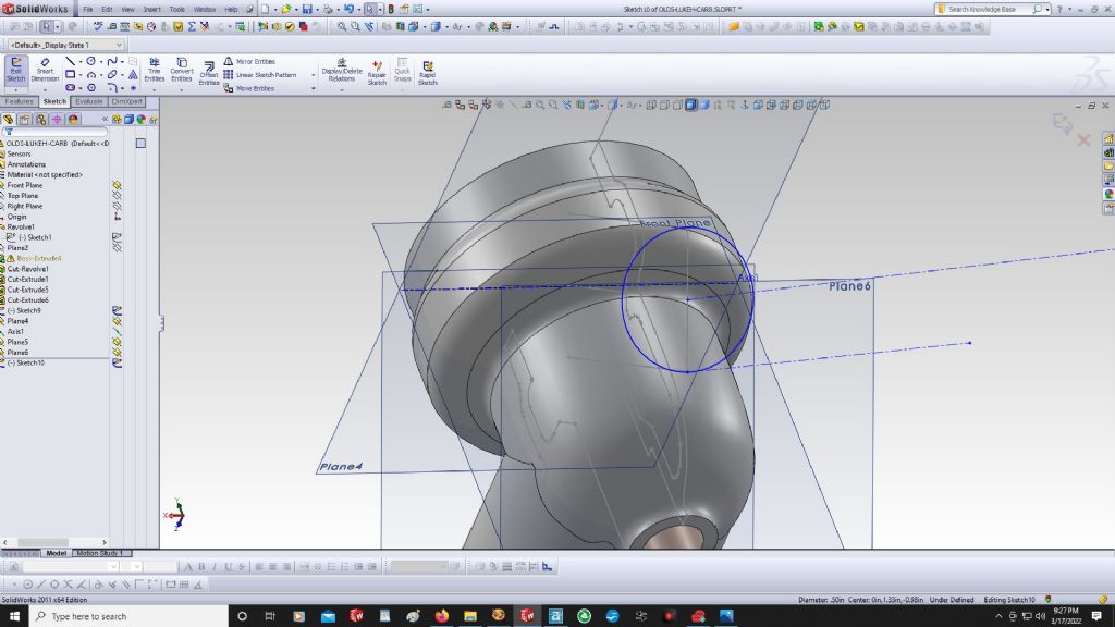
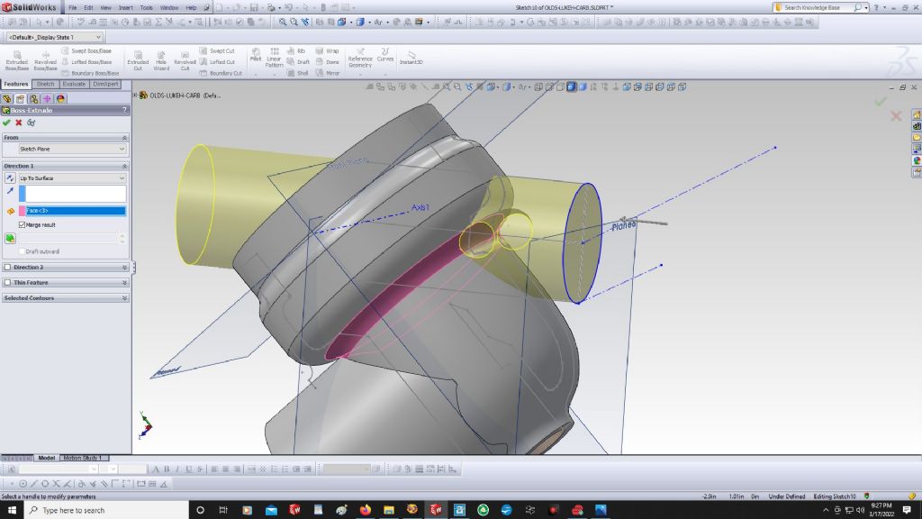
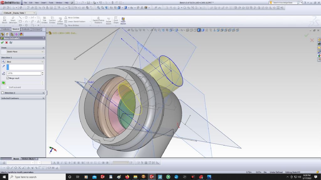
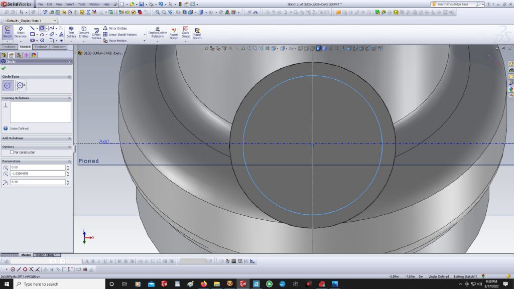
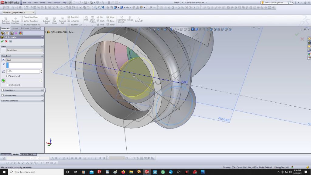
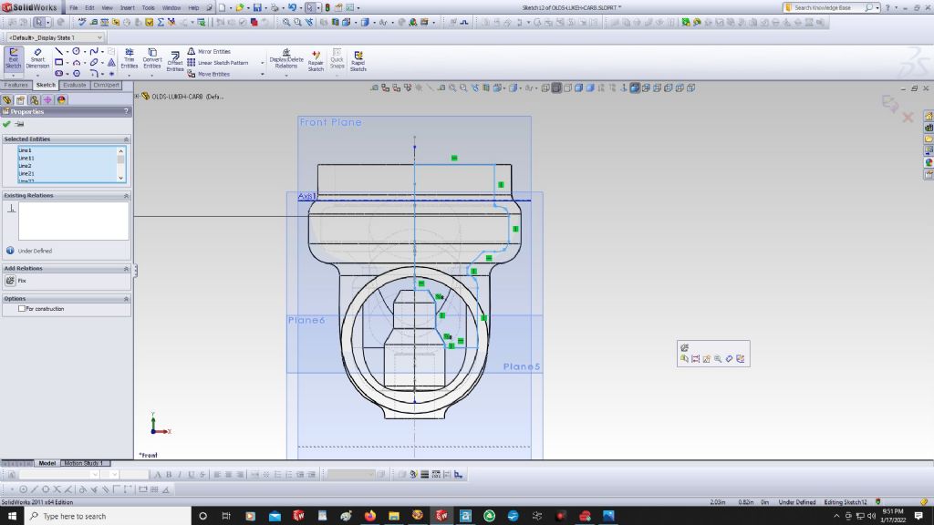
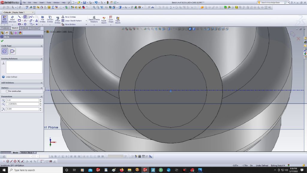
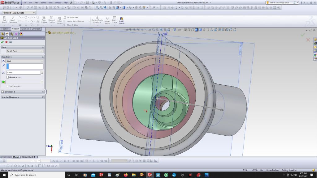
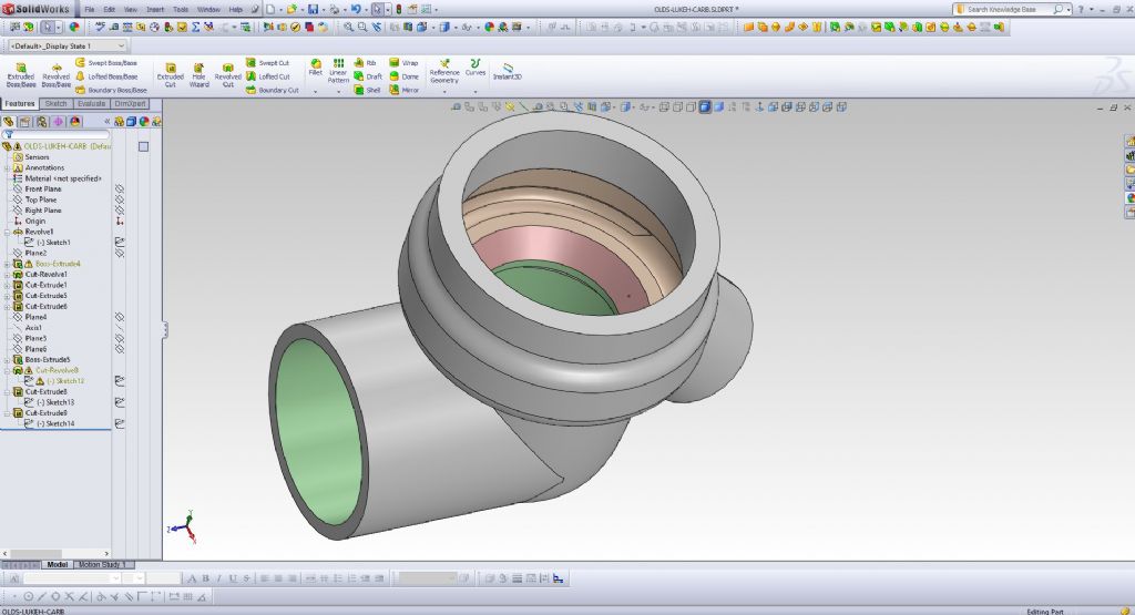
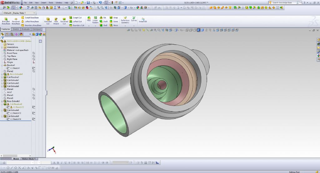
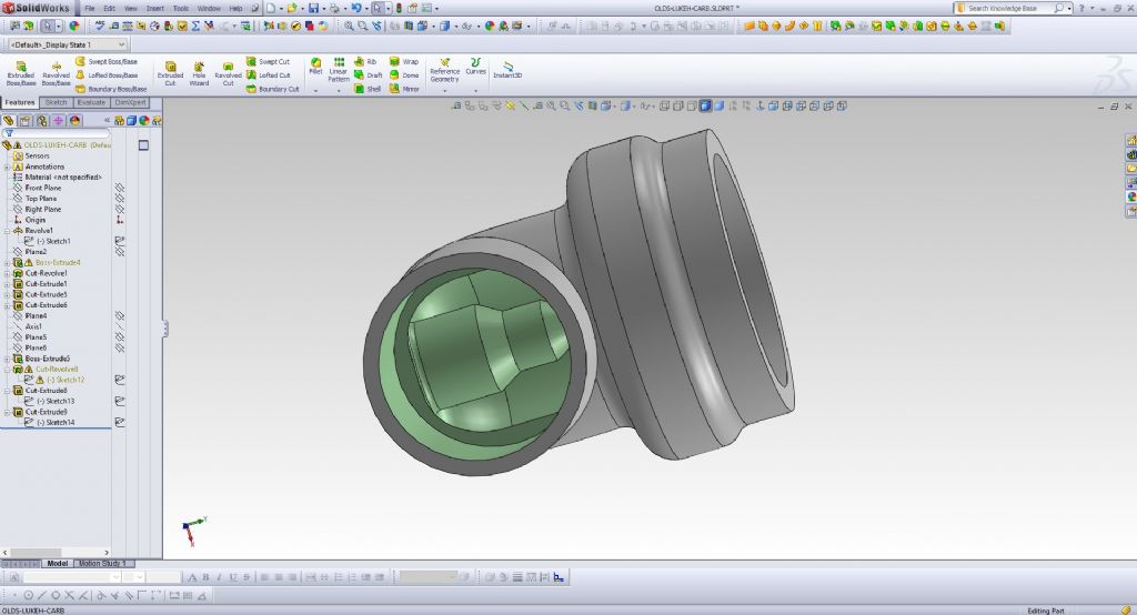
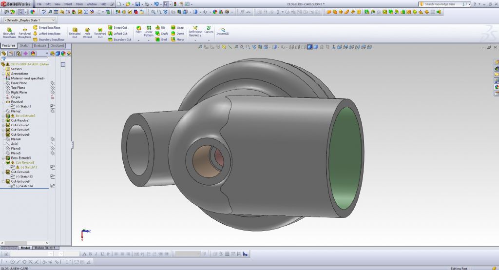
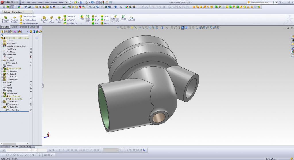
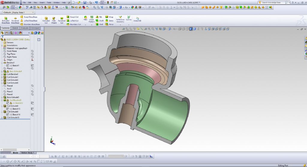
      This is my first attempt to model a Lunkenheimer carburetor.

      I made this model a few weeks ago.

      I think it is almost done, but perhaps not 100%.

      Not too bad for a first attempt, in my opinion, and not much time spend on this model (perhaps 2 hours).

      I had never modeled a carb before, and so I just stumbled my way through the model.

      My approach to modeling is to create a model in any way that I can, no matter how crude or clumsy the appoach or model may be.

      If I succeed in creating an accurate model, even if I used very crude methods, then I use the model "as-is".

      If I revisit the model later for use on another engine, I may re-model some parts of it, or create a new model entirely, if I think of a better more efficient approach.

      The main thing is to create a usable model.

      Don't worry about winning a "3D modeling efficiency" award; just get it done and refine your technique later over a period of time.


      image1.jpg


      image2.jpg

      image3.jpg

      image6.jpg


      image7.jpg


      image9.jpg


      image10.jpg


      image12.jpg


      Edited By PatJ on 11/05/2022 03:23:07

      Advert
      #21383
      PatJ
      Participant
        @patj87806
        #597783
        PatJ
        Participant
          @patj87806

          More screen captures.

          image13.jpg

          image14.jpg

          image16.jpg

          image17.jpg

          image18.jpg

          #597784
          PatJ
          Participant
            @patj87806

            More screen captures.

            image21.jpg

            image22.jpg

            image23.jpg

            image24.jpg

            image25.jpg

            image26.jpg

            image27.jpg

            image29.jpg

            #597785
            PatJ
            Participant
              @patj87806

              More screen captures.

              image30.jpg

              image32.jpg

              image33.jpg

              image34.jpg

              image35.jpg

              image36.jpg

              image37.jpg

              image38.jpg

              image41.jpg

              #597786
              PatJ
              Participant
                @patj87806

                My intent as with all of my 3D models is to 3D print patterns, and then cast the parts.

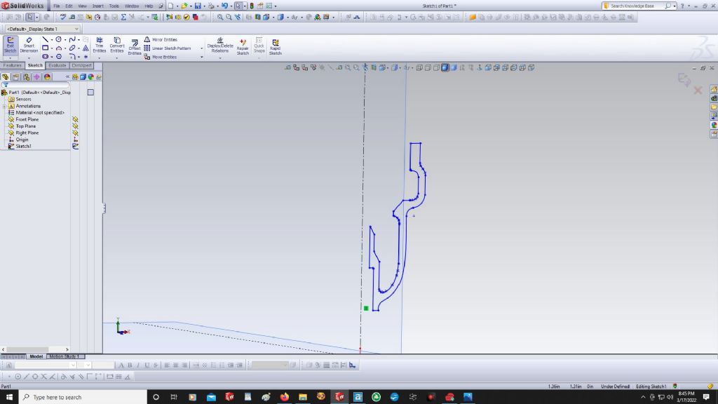
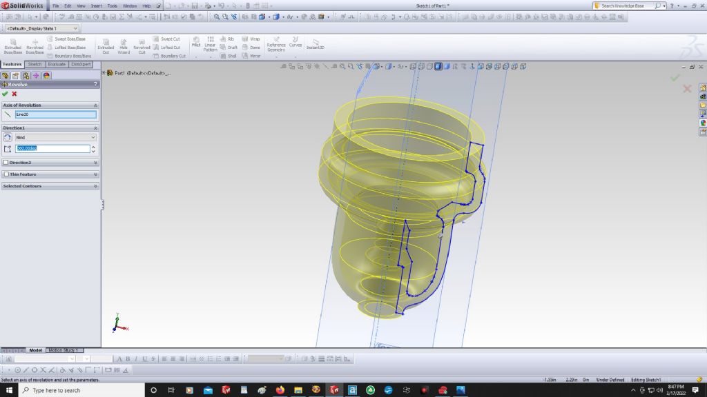
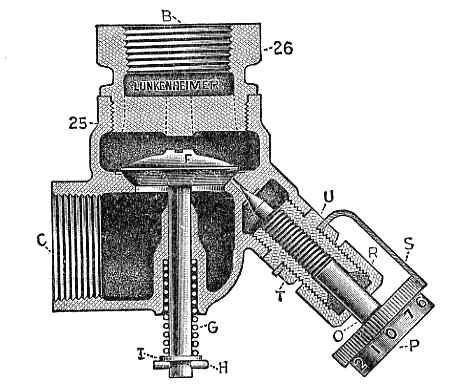
                The original sectional sketch that I used to rotate the initial bowl shape was taken from an old engraving of a Lunkenheimer carburetor, by importing the sketch as a raster image, and then tracing over it to create a 2D sketch, which I imported into Solidworks on my initial sketch plane.

                There are many ways to create this model, and many would no doubt be better than the methods I used, but I was able to get through it in a short period of time.

                The best way to finish a 3D model is to actually start a 3D model.

                Nobody I know of learns 3D modeling without diving in there and getting their hands dirty.

                .

                carb58.jpg

                Edited By PatJ on 11/05/2022 03:26:15

                #597787
                PatJ
                Participant
                  @patj87806

                  If I can get a 3D model printed fairly accurately, for use as a pattern, then I can touch it up either by lightly grinding/sanding/cutting on a few spots, or filling a few spots with filler.

                  Most 3d models are not perfect, but the intent is to 3D print something that can be made usable with some minor touch-up work.

                  .

                  Edited By PatJ on 11/05/2022 03:29:15

                  #597908
                  lee webster
                  Participant
                    @leewebster72680

                    That is a good piece of work! Will you cast the part in brass?

                    In the past when I have sanded and filled my 3D prints I then sprayed them with rattle can car paint. They always seemed to have the layer lines showing to some extent. I recently cast an aluminium picture frame from a 3D print that had been sanded and filled, but not painted. The finish was much better. I think the car paint had reacted with the PLA print, "swelling" the layer lines a little. I wonder if a water based spray paint would also affect PLA? Myfordboy brushes his 3D prints with ordinary emulsion paint. It seems to work OK.

                    #597916
                    PatJ
                    Participant
                      @patj87806

                      Thanks, I have cast a few items in brass, but it is always a struggle to reach pour temperature before you burn off all the zinc. I think some use a cover of various types to keep the oxygen away from the molten brass.

                      And one must avoid the zinc fumes too, since they will make you ill.

                      The metal that everyone recommends these days for the non-grey iron parts is silicon bronze.

                      I don't have any silicon bronze at the moment, and metal prices are over the moon right now, but it looks like I will need to purchase some silicon bronze, enough to make small parts like carbs and such.

                      My approach to pattern making has morphed over the years.

                      I originally hand-made all of my patterns from either wood or steel.

                      As I began to get more familiar with 3D modeling, and then 3D printing, I began to use 3D printed patterns more and more.

                      I really like to hand-make patterns in wood, but I have a long list of engines that I want to cast, and printing 3D patterns seems to be the most expeditious way to go, in order to get a lot of patterns made quickly.

                      And sanding wood patterns and cutting the wood generates a lot of dust, which goes everywhere in the shop.

                      I spray painted my first wood patterns, but I don't like the fumes and mess that a spray can will generate in the shop. Sprayed on paint does not seem to sand all that well either.

                      I discovered shellac a few years ago, and I really like to use it these days in lieu of paint.

                      The fumes from shellac are pretty minimal, and most importantly, shellac dries in as fast as 15 minutes (I usually wait at least 30 minutes for a recoat), And shellac seems to sand well, for a smooth finish.

                      Many use standard paint schemes for their patterns, but much of my work is one-off, and it is not worth the effort to color code things like coreprints, etc.

                      I am far more concerned with how the castings look and turn out than I am with how the pattern looks.

                      I have heard of some using volatile chemicals to melt the surface of PLA 3D printed parts, but I am really trying to get away from as many toxic products in the shop as possible. I do have a commercial chemical respirator, but it is a nusiance wearing it, especially during hot weather.

                      The tiny lines/cracks in PLA prints are surprisingly deep and difficult to fill.

                      It takes too many coats to try and fill the lines with paint or shellac (for me anyway).

                      I have resorted to using a sheetrock wall patch compound that is a powder that I mix on demand.

                      I skim the entire PLA or wood pattern with it, and then sand it smooth.

                      I can generally smooth a pattern in one go around with patching compound, but the disadvantage is that over time, it may flake off of the pattern.

                      Bondo is too thick and stiff to sand without damaging the pattern, and the fumes from it are bad.

                      The next thing I am going to try when I get a bit of time is auto body repair material called "skim coat".

                      Here is a link to one product; there are many manufacturer's of this material.

                      SKIM COAT | POLYESTER GLAZING PUTTY

                      It is a thin flowable polyester glazing compound, used to fill pinholes and other small imperfections on auto bodies. Sands in 15 minutes. It is a two-part system that requires a hardener (unfortunately).

                      Adheres to multiple surfaces. Non-bleed.

                      I think a polyester skim coat is the answer to filling the lines on a 3D printed part.

                      And if applied in a very thin coat, it should be easy enough to sand off most of it off back to the original 3D part surface, while filling the lines.

                      I don't think skim coat is thick enough to create fillets and such, but I add the fillets in the 3D modeling program, and so all I need the skim coat to do is get rid of the lines.

                      So that is the game plan at this point.

                      .


                      Edited By PatJ on 12/05/2022 02:37:31

                      #597919
                      PatJ
                      Participant
                        @patj87806

                        I found a video on various skim coat products, and it looks like the thinner product "seal skin" may be better suited to what I am trying to do.
                        As long as I don't get a lot of sagging, the thinner material I think would work better.

                        As I understand it, you can mix these products, and so you could use 1/2 seal skin and 1/2 skim coat, to perhaps find a good balance between flowability and resistance to sagging on vertical surfaces.

                        .

                        #597923
                        JasonB
                        Moderator
                          @jasonb

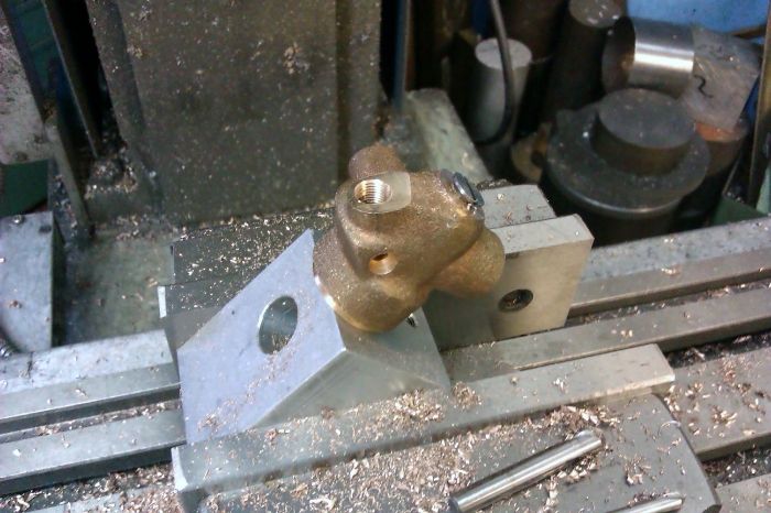
                          How easy is it to produce the core and corebox from those drawings using Solidworks?

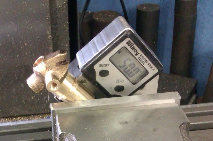
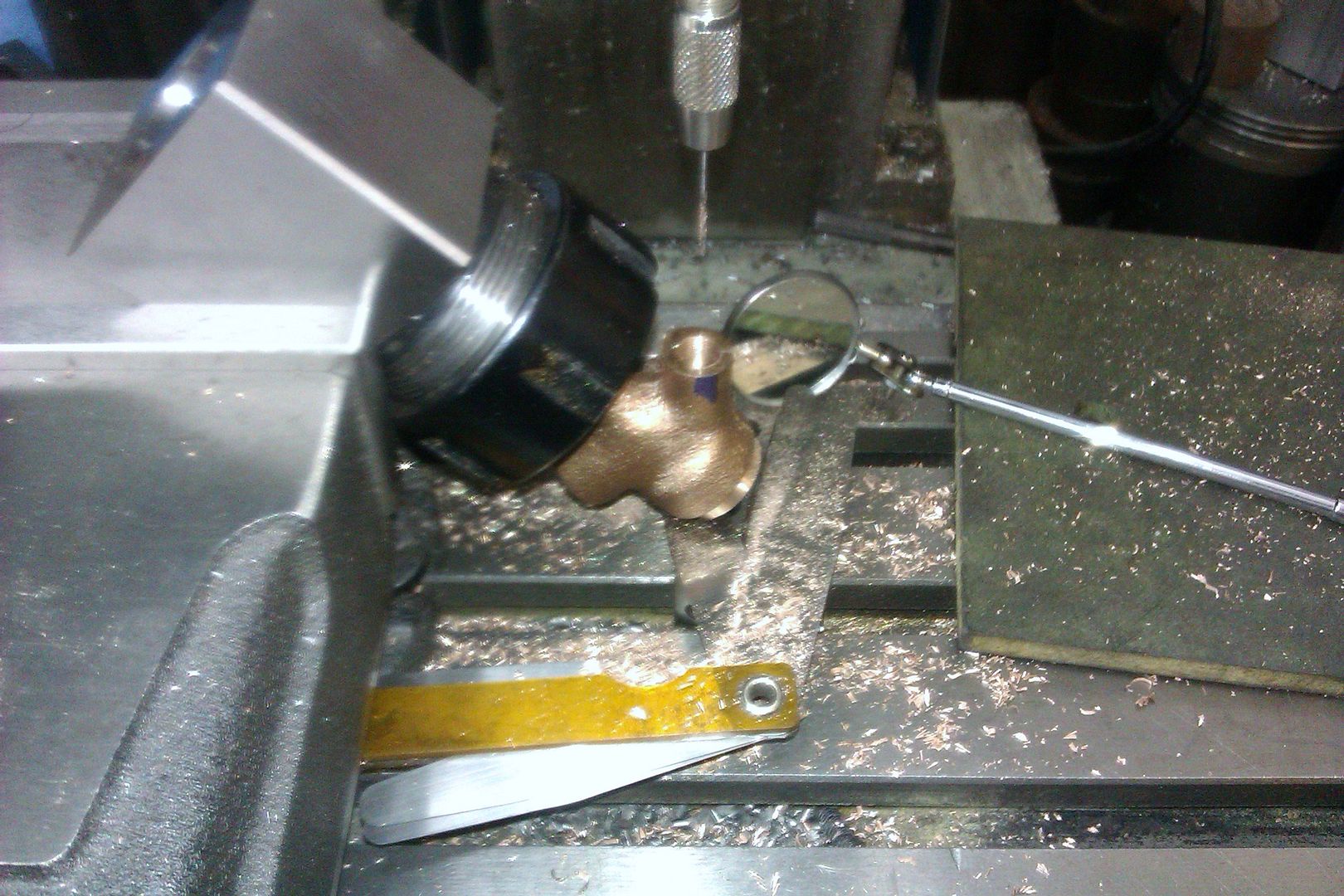
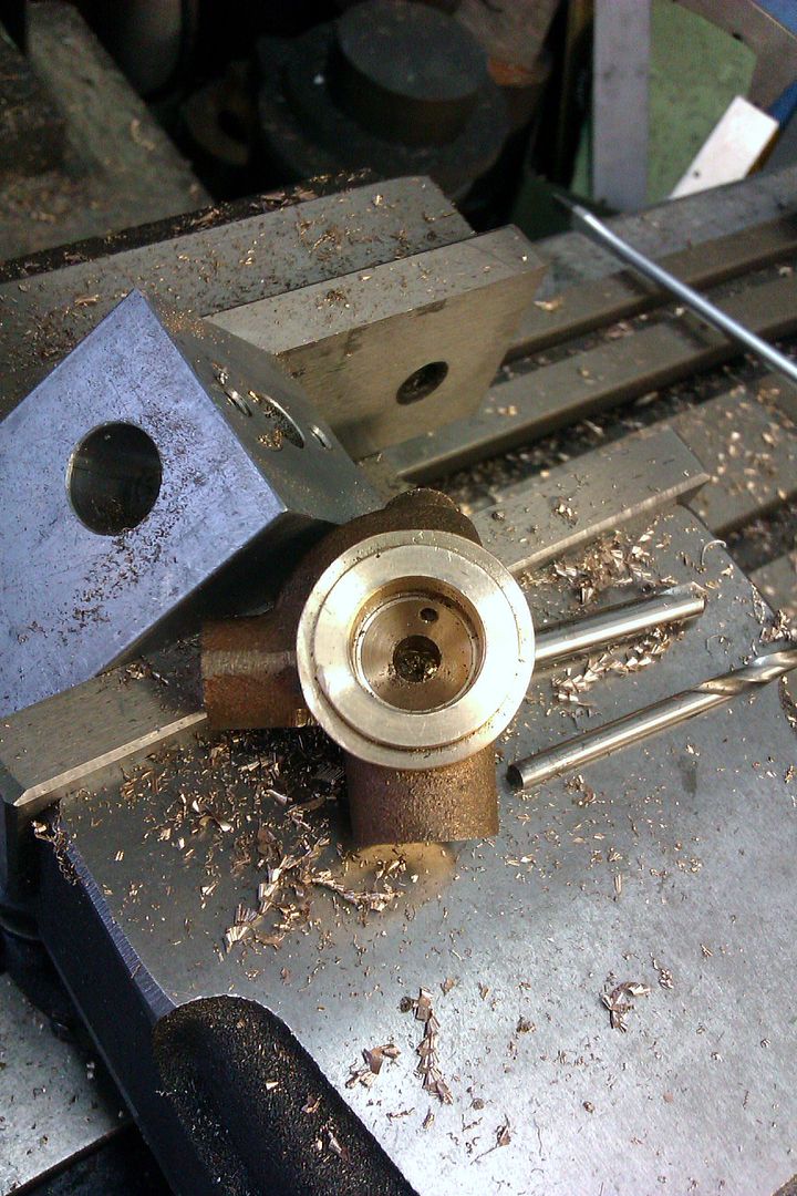
                          All the Lunks I have made have the bottom valve guide a separate part so coring is a lot less complex. The fun part is machining the valve seat and getting the fuel hole to exit through the seat.

                          Old plumbing fittings such as valves may be a cheap source of Bronze if you don't mind the dross.

                          #597924
                          PatJ
                          Participant
                            @patj87806

                            They do make some model engine Lunkenheimer carbs for sale, and they look pretty nice, but you know me, I like to make my own stuff when possible, and I like to find out what is possible.

                            Of course the 3D model has to be made into a pattern, which means adding machining allowance at the seat, at the threaded hole entries, and sometimes closing holes that are too small for cores. Small holes are often better drilled post casting.

                            Just thinking outloud, without really giving it a lot of thought, I would print two pattern halves, without the center stem guide, and print the stem guide as a single retractable solid piece.

                            The two pattern halves would act both as patterns (with some temporary coreprints glued on), and also act as a corebox.

                            I would assemble the two halves, insert the stem guide, ram the core, remove the stem guide, and then split the pattern halves, to make the core.

                            A little more thought would have to be given about how to make the extensions on the core that fit into the coreprint areas.   You can always cement pieces of cores together, but it would be better to make the core all in one go.

                            The core could be made with sodium silicate sand, resin bound sand, or the old linseed oil method.

                            I have never tried the linseed oil method, but they use to make some very intricate cores that way, such as the Speedy Twin passages, which are very complex.

                            The show stopping trick may be as you say, drilling the fuel hole into the seat.

                            I am not sure how you would do that without breaking off some tiny little micro drill bit.

                            Anyone drilled tiny holes before? How do you approach that?

                            .

                            Edited By PatJ on 12/05/2022 08:07:15

                            #597926
                            PatJ
                            Participant
                              @patj87806

                              The plumbing bronze is not a bad idea really.

                              It would certainly be cheaper if you could find some scrap bronze.

                              One has to be careful about scrap bronze, since some of it contains very toxic materials, and I am not sure how to distinguish which bronzes have the bad stuff in them.

                              I am not against buying new plumbing stuff and melting it, if the price is low enough.

                              I have seen some mini electric furnaces that will melt bronze, but according to one source, either the crucible or the elements don't last very long.

                              For little casting work in the past, such as casting individual flywheel spokes, I have used a small furnace, and a dip-out ladle, with aluminum. For bronze, I would probably build a mini-furnace that is 3,000 F rated, with a mini oil burner.

                              It would not really be worth the effort to fire the big furnace to cast something this small.

                              Obviously this item would lend itself to the lost wax process, where an entire tree of carb bodies could be cast all at once, but I am not set up for lost wax, and am not going to spend the money to use lost wax.

                              I can make multiple resin-bound molds and cement them to one long runner, and essentially duplicate what would happen with lost wax.

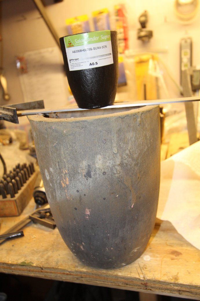
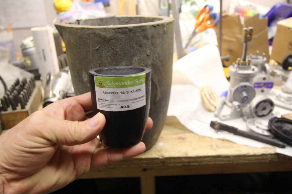
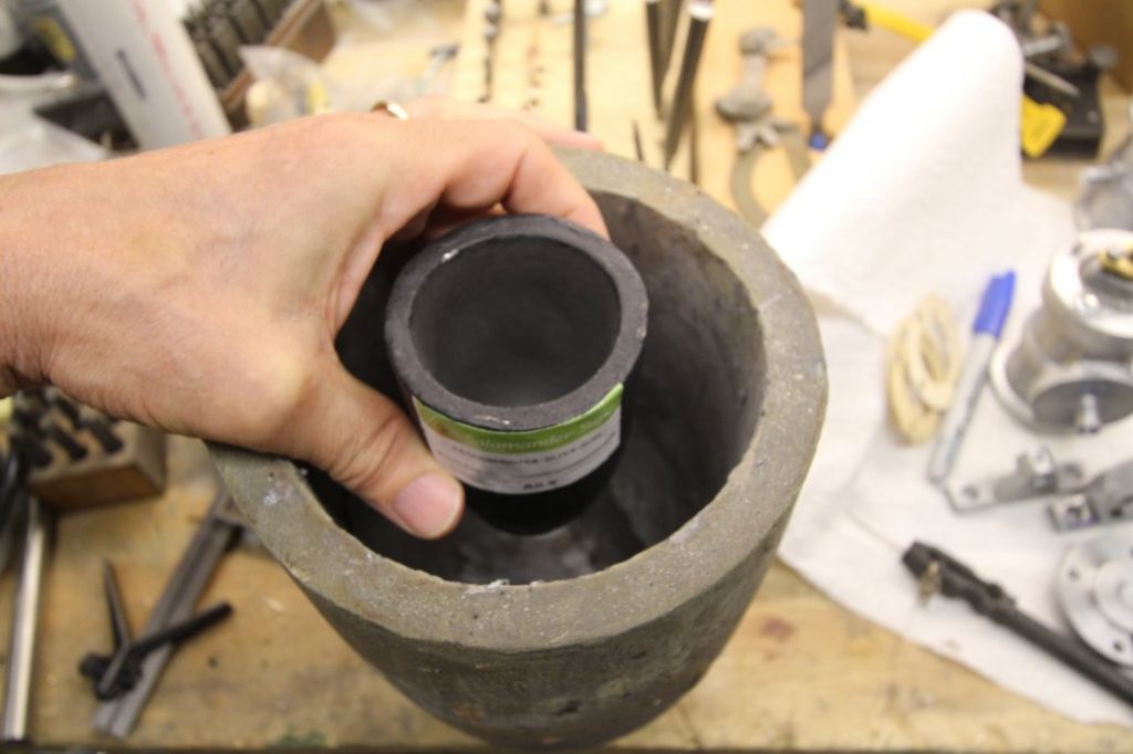
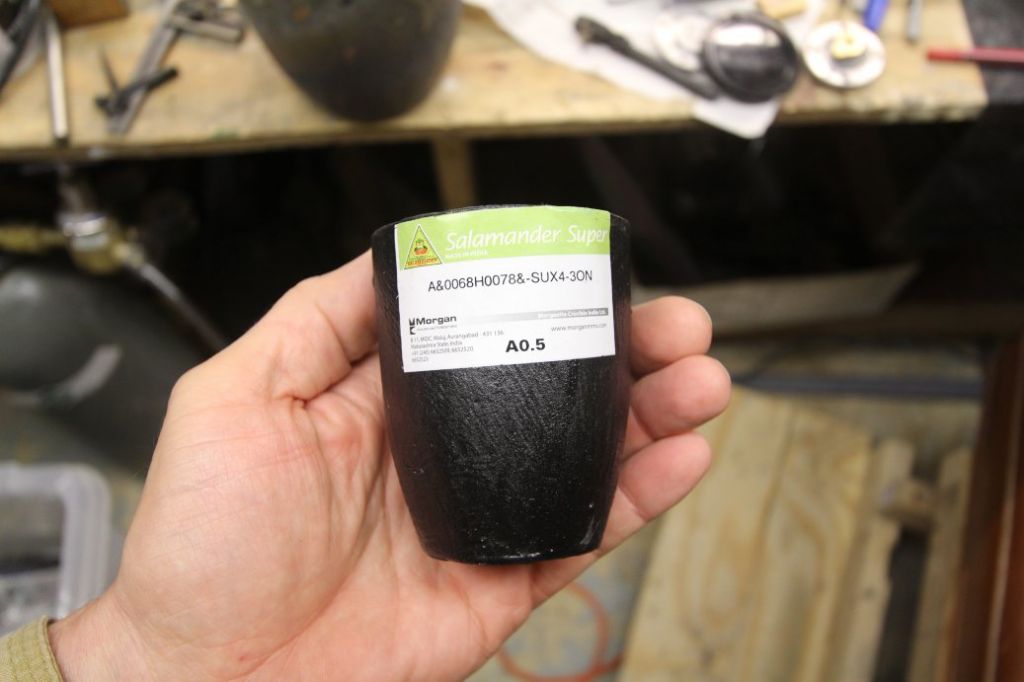
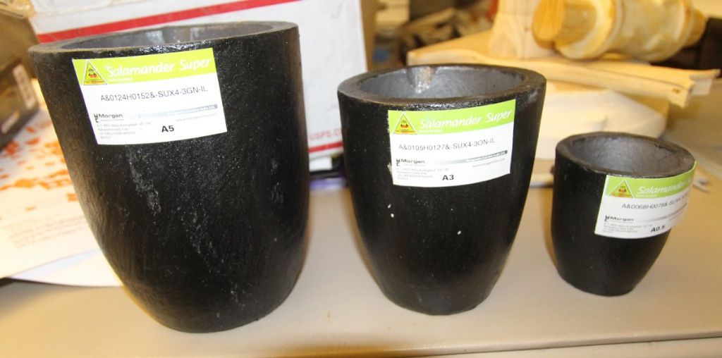
                              I bought some small crucibles. Photos attached.

                              I still say that the trick would be drilling that fuel hole. I would not start to make a casting without mastering drilling some tiny holes first.

                              The 0.5 crucible is compared to an A10.


                              rimg_8415.jpg

                              rimg_8416.jpg

                              rimg_8417.jpg

                              rimg_8418.jpg

                              Edited By PatJ on 12/05/2022 08:21:46

                              Edited By PatJ on 12/05/2022 08:22:56

                              #597927
                              PatJ
                              Participant
                                @patj87806

                                I have a range of crucibles I could use, but an A0.5 would be really easy to handle, if it were large enough, and I think it would be large enough for one or two carbs of a model engine size..


                                rimg_8566.jpg

                                Edited By PatJ on 12/05/2022 08:27:35

                                #597931
                                PatJ
                                Participant
                                  @patj87806

                                  Here is an example of a tabletop furnace used for bronze or brass.

                                  If the furnace coils or crucible did not last long, then this may be a poor choice, but it would be much cleaner than an oil-fired furnace, and you could use it indoors (in a ventilated space).

                                  I will do some digging and see if I can figure out how long these units last.

                                  See 5:14.

                                  .

                                  #597941
                                  JasonB
                                  Moderator
                                    @jasonb

                                    #597945
                                    noel shelley
                                    Participant
                                      @noelshelley55608

                                      Pat,IF your loosing much Zinc then you need to heat faster, cold to pour in 20mins ! You cannot avoid some zinc loss as it boils at 907c and your pouring temp will be over 1000c., bronze up to 1150c. A dip pyrometer is vital for good success. Pea sized crushed charcoal as a cover and marine pumps and valves as a source of bronze. A small propane furnace, with K23 lining and A4 crucibles will work fine. Electric is tooo slow unless it's induction, and that's very costly . Noel.

                                      #597955
                                      PatJ
                                      Participant
                                        @patj87806

                                        Jason-

                                        That is some nice carb work.

                                        I guess I thought the fuel hole would be smaller than that, but apparently not.

                                        I have mounted a dremel on my drill press at times, and that would perhaps give enough rpm for a small drill bit.


                                        Noel-

                                        As I think back to 2012, when I built a foundry, I was clueless about how to do most of it.

                                        I built a furnace, and an oil burner, and the furnace mass was too high, and so it had a very slow heat-up time.

                                        I didn't have a clue about how to tune my diesel burner, and I made the false assumption that more fuel/air was better.

                                        The hottest furnace interior is produced when a burner injects the correct ratio of fuel and air into the furnace, in order to allow all of the fuel to completely combust.

                                        The amount of fuel a furnace can combust is determined by its size.

                                        I started out using 6 gallons per hour or more, and the furnace was actually running cold.

                                        It took me a long time to realize that the highest temperature for my furnace was with the burner operating at about 2.7 gal/hr.  Less turned out to be more.

                                        When I was trying to cast brass, naval brass, and red brass, I am sure my burner was not tuned correctly, and thus that exacerbated the heat time, which was very slow.

                                        I will have to go back and revisit a silicon bronze melt, know that I know how to run a burner.

                                        I use a pyrometer for aluminum, and have one I can use for bronze too.

                                        For iron, I don't use a pyrometer, since the iron-temperature pyrometers are extremely expensive, and the tips don't last very long.

                                        Once you understand how to melt iron, it is actually easier (in my opinion) than brass/bronze.

                                        Generally a #10 crucible of iron will reach pour temperature in about an hour, at 2.7 gal/hr diesel.

                                        You can tell when you are at pour temperature because sparklers will start to fly out of the melt at pour temperature.

                                        I will have to try the charcoal.

                                        I considered an induction furnace, but I don't want to set a demand, and then have to pay for that demand all year, whether I cast anything or not. Induction furnaces are not cheap either.

                                        I call my oil-fired furnace a "poor man's induction furnace", but I can't complain, my furnace works very well, and works consistently.

                                        .

                                        Edited By PatJ on 12/05/2022 13:01:56

                                        #597956
                                        PatJ
                                        Participant
                                          @patj87806

                                          A fellow who sells aluminum ingots from the Pacific Northwest told me how to determine howt the maximum fuel flow rate for any furnace can be determined.

                                          The method is to pick a flow rate, such as 1 gal/hr, and then increase that amount until you get perhaps 12" of flame out the hole in the lid.

                                          Then you increase the combustion air flow (I use a variable speed leaf blower), and the flame should go back into the lid.  When there is little or no flame coming out the furnace lid, this means that the fuel is fully burning in the furnace, and not burning when it hits the outside air.

                                          You continue to incrementally increase fuel flow, and then air flow.

                                          At some point, when you increase the fuel flow, and then increase the combustion air flow, instead of the flames drawing back into the furnace, they will become larger outside the furnace.

                                          This point is slightly beyond the point of maximum fuel flow that can be competely combusted inside the furnace.

                                          Using any more or any less fuel/air than this maximum amount will cause the furnace to run cooler.

                                          .


                                          Edited By PatJ on 12/05/2022 13:10:35

                                          #597974
                                          lee webster
                                          Participant
                                            @leewebster72680

                                            I watched a video on youtube this morning posted by Uncle Jessie. He was experimenting with car paint stopper or glazing compound. It is available in small tins or tubes and it is spread very thinly onto the surface, in his case, a3D print. But he also used a small cheap airbrush to spray a coat of this filler that was thinned with acetone. It seemed to work OK but all the chemicals meant that a very good resperator was called for. Myfordboy uses premixed household filler, I am not sure if he also uses the stuff you mix with water. Some casters on youtube melt aluminium and copper to produce a brass lookalike, but it seems very hard to machine.

                                            #598233
                                            PatJ
                                            Participant
                                              @patj87806

                                              An airbrush spray-on methods is not a bad idea, depending on the thickness of the material.

                                              I do have a sprayer that is specifically designed to apply a heavy slurry for coating the interior of sand molds with a ceramic mold coat.

                                              Even then, the slurry is a pretty fluid liquid though, and nothing like a putty.

                                              I am trying to avoid the acetone route, although the fumes from a polyester skim coat would still require a commercial chemical-rated respirator.

                                              The wall patch material I use is a good mix between ease of sanding and hardness, ie: its not too hard and not too soft, and you can sand it off relatively quickly.

                                              I have tried Durham's putty, and the label is correct, ie: it dries "hard as a rock", and so it basically impossible to sand off without damaging the pattern itself.

                                              I was using DAP spackling compound, which is my favorite, but it is pre-mixed, and every time I opened the can to use it, it was hardened into a solid useless mass.

                                              The wall patch compound I use now is a mix-on-demand powder, and is almost as easy to use as the DAP material, and it never goes bad, since it is a powder (if you keep it dry).

                                              I have seen the aluminum/brass/bronze alloys in online videos, and at first I thought that was something new, but then I discovered that it has been used for many years.

                                              A buddy of mine sent me a sample of it, and it seems as hard as the face of an anvil.

                                              I am not sure if there is a way to raise the machinabilty of aluminum bronze.

                                              I think just straight bronze is the way to go. I have seen a few home-brew bronze recipes, but I think I will stick with some known material, such as plumbing bronze, and thus have a known machinability.

                                              Edit:

                                              I guess if you could find a balance between thickness, and spray-ability, then you could spray on the polyester skim coat, assuming it did not sag.

                                              There is some skim coat recommended for horizontal surfaces only, and I know that could be sprayed, but would it sag?.

                                              One trick that I use with the water-based wall patch compound is to glob it on to some extent with a brush or something, let it begin to set for a few minutes, then take a damp cloth and wipe it down to a thin thickness, and shape the fillets and such to final shape.

                                              This method works well, and saves a ton of time.

                                              It could perhaps be used with a polyester skim coat, if you could figure out the correct solvent to use.

                                              .


                                              Edited By PatJ on 14/05/2022 11:16:43

                                            Viewing 21 posts - 1 through 21 (of 21 total)
                                            • Please log in to reply to this topic. Registering is free and easy using the links on the menu at the top of this page.

                                            Advert

                                            Latest Replies

                                            Viewing 25 topics - 1 through 25 (of 25 total)
                                            Viewing 25 topics - 1 through 25 (of 25 total)

                                            View full reply list.

                                            Advert

                                            Newsletter Sign-up