3D Challenge – Side Lever Engine

Advert

3D Challenge – Side Lever Engine

Home Forums CAD – Technical drawing & design 3D Challenge – Side Lever Engine

Viewing 16 posts - 1 through 16 (of 16 total)
  • Author
    Posts
  • #596779
    PatJ
    Participant
      @patj87806

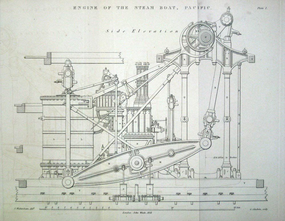
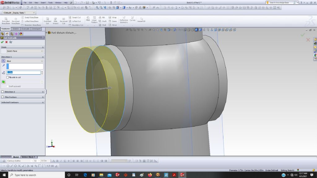
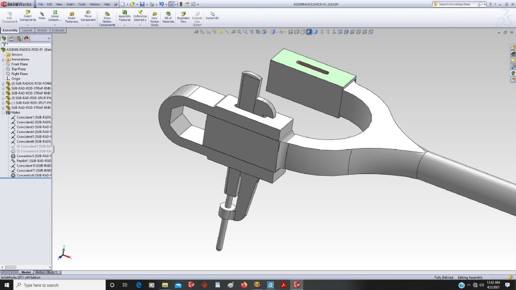
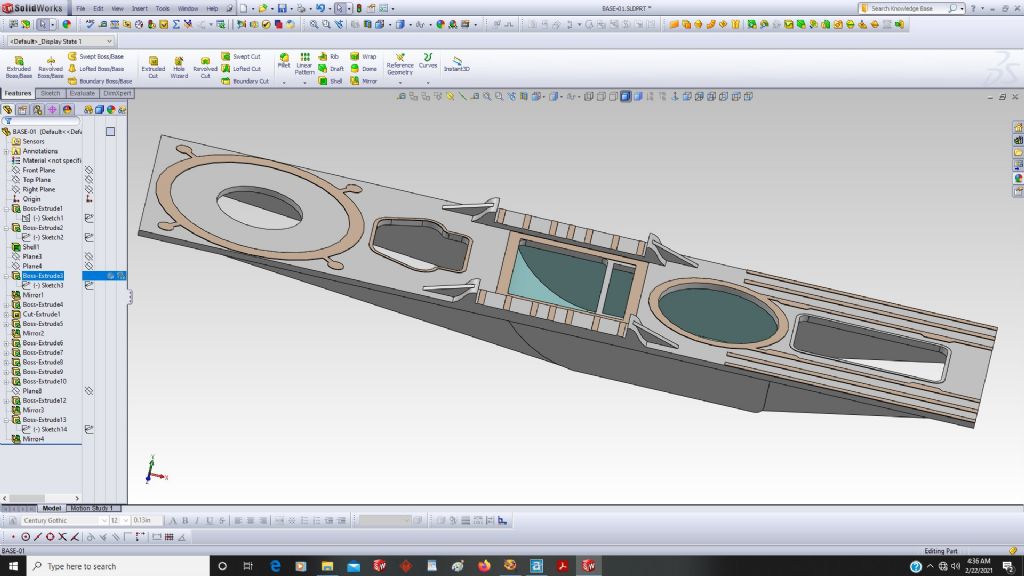
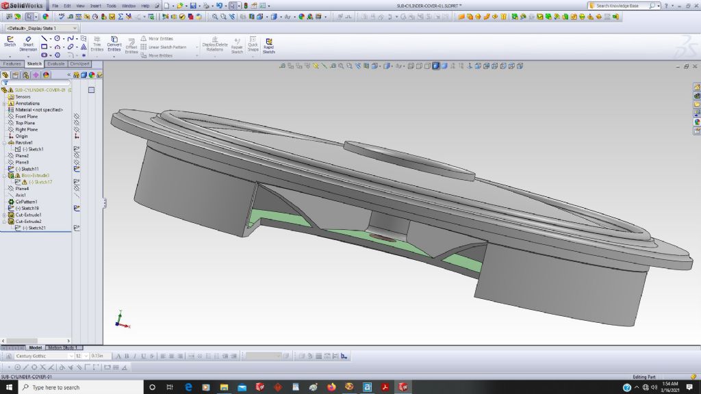
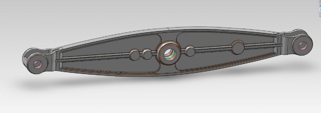
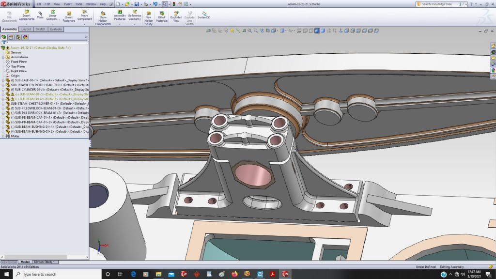
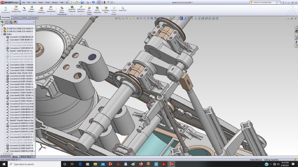
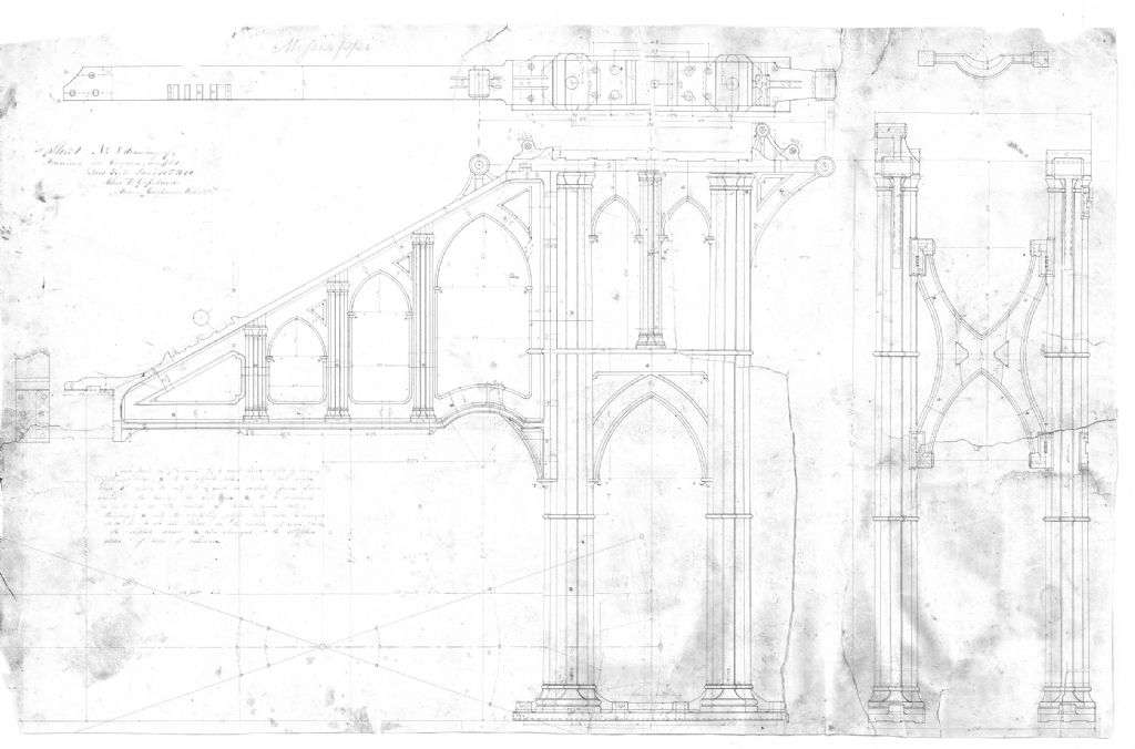
      I had someone send me some scans of side lever engine drawings (originals from 1840), and they were dreadful drawings, in dreadful condition.

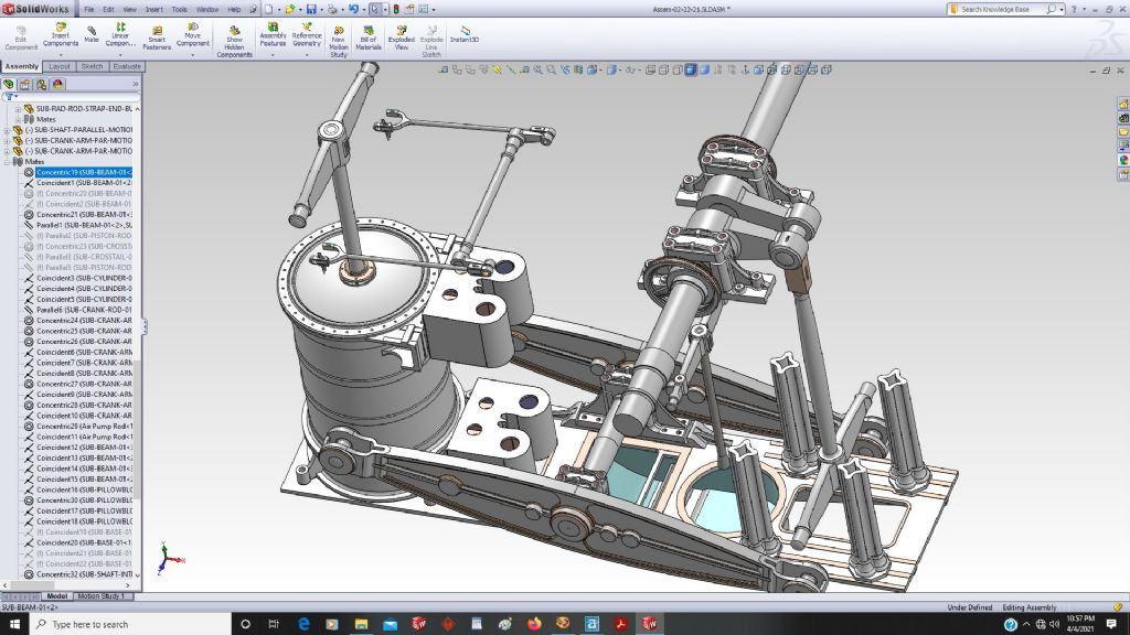
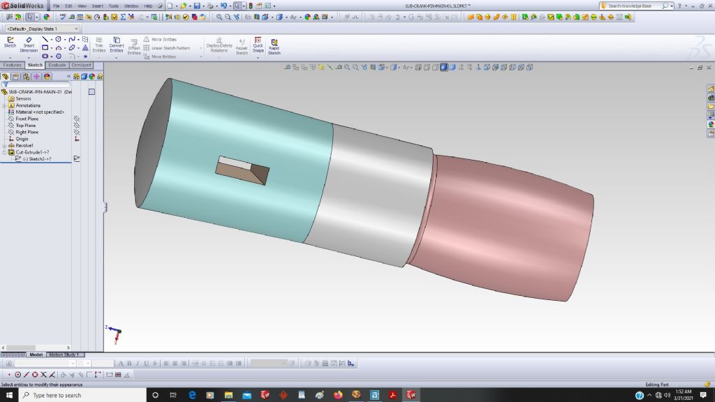
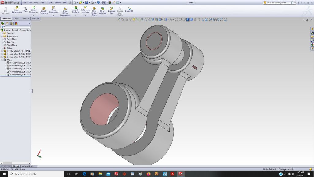
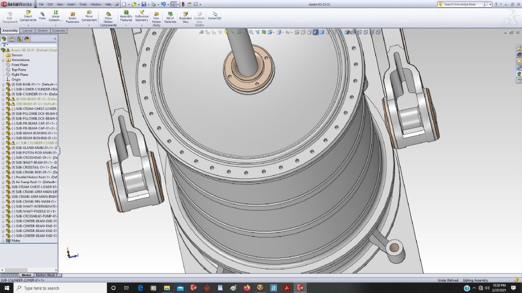
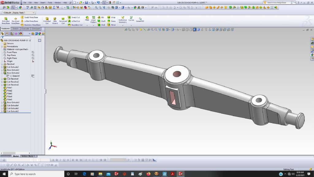
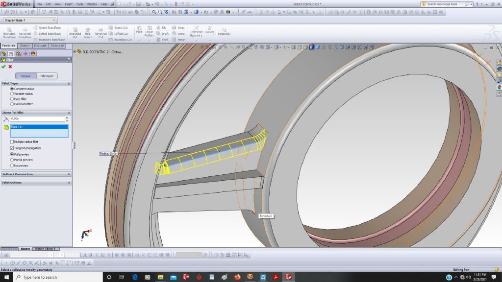
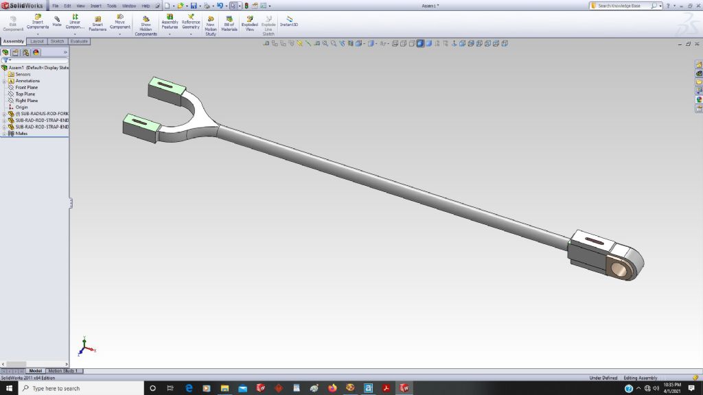
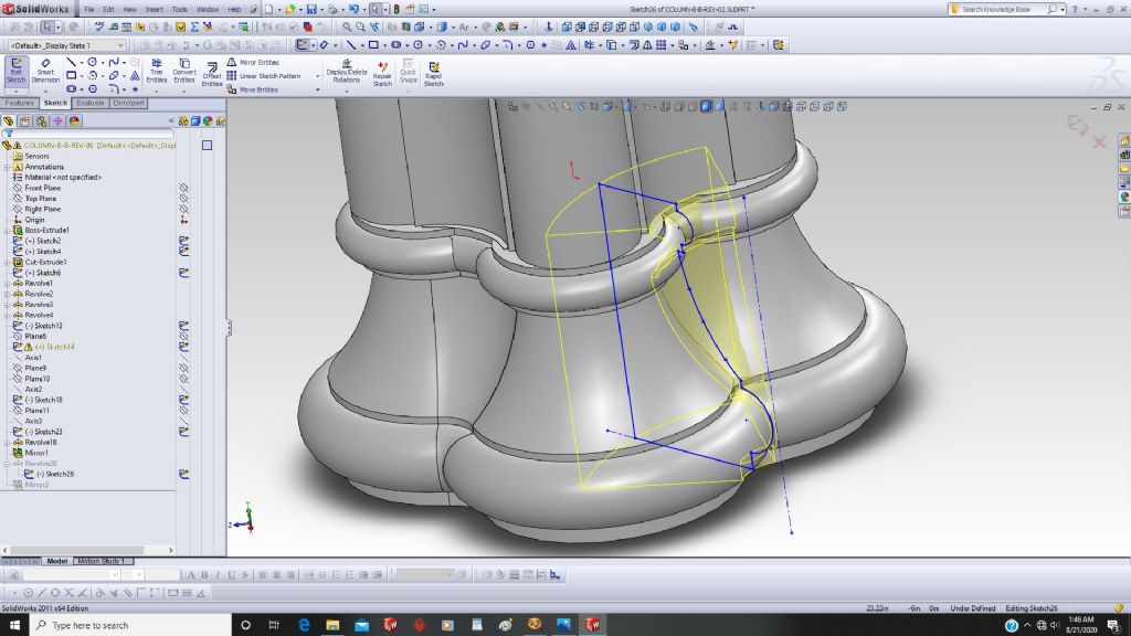
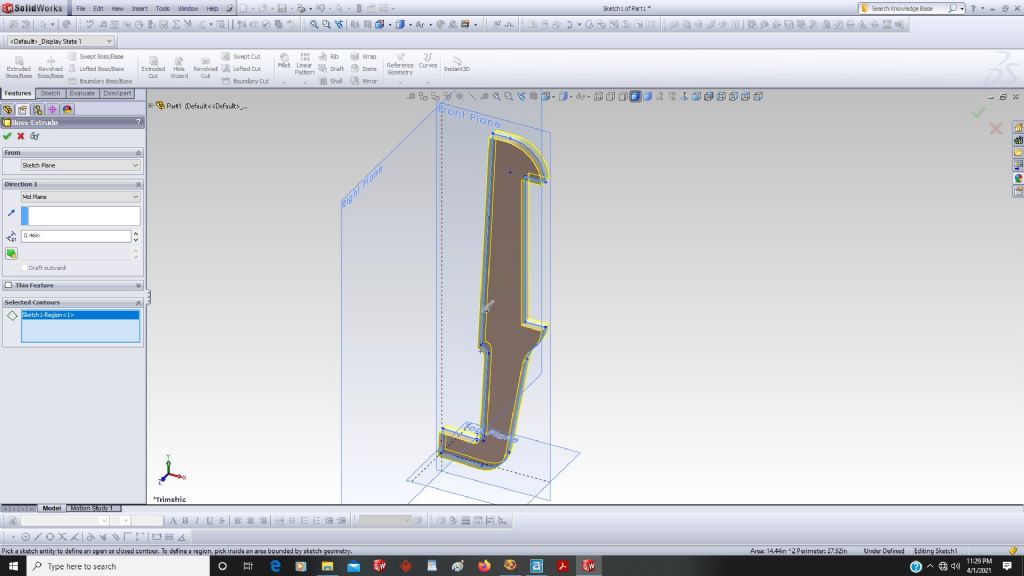
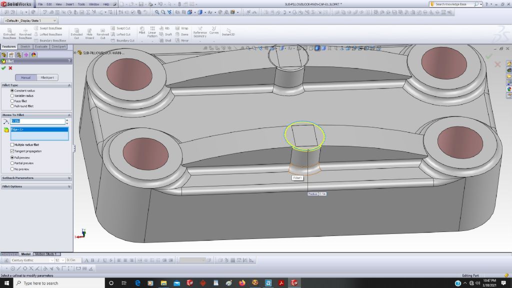
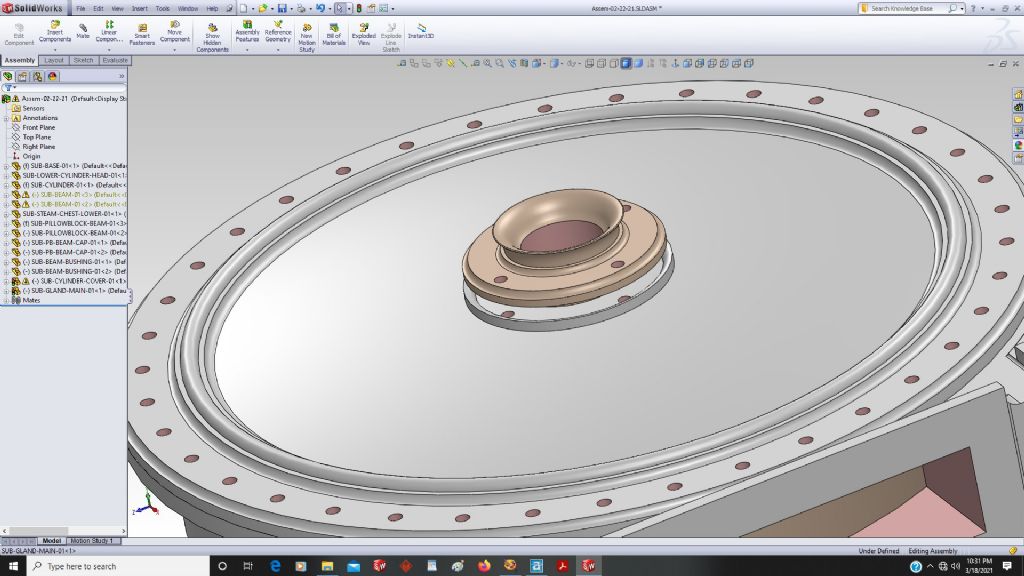
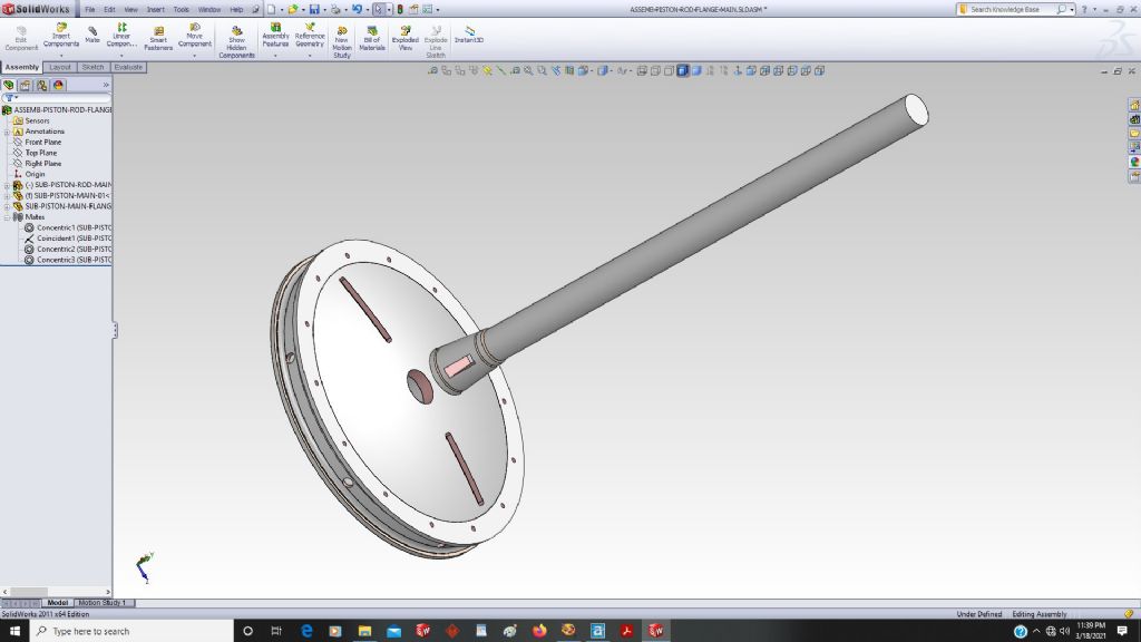
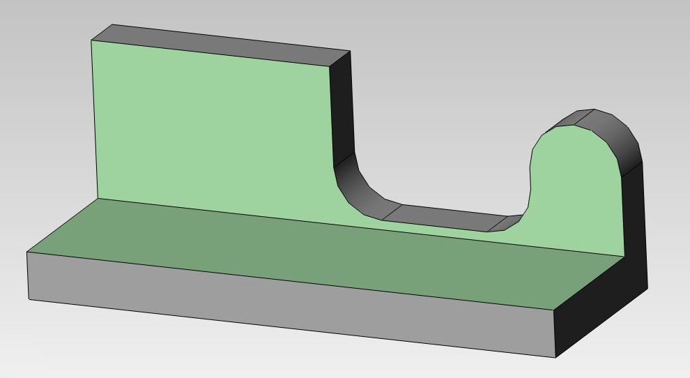
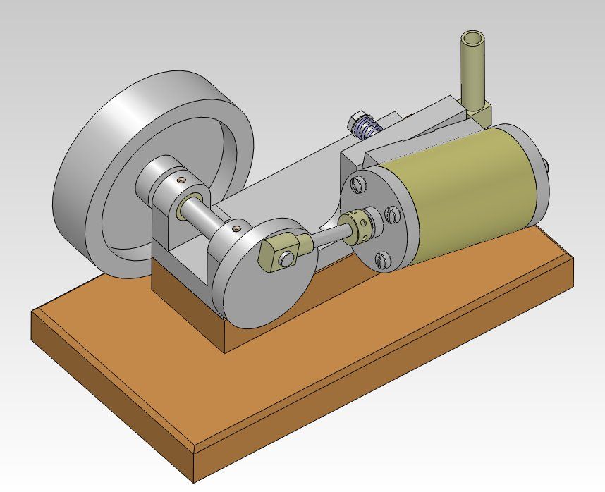
      I worked on this engine last year when I had more time, and made some good progress with making accurate 3D models of many of the parts.

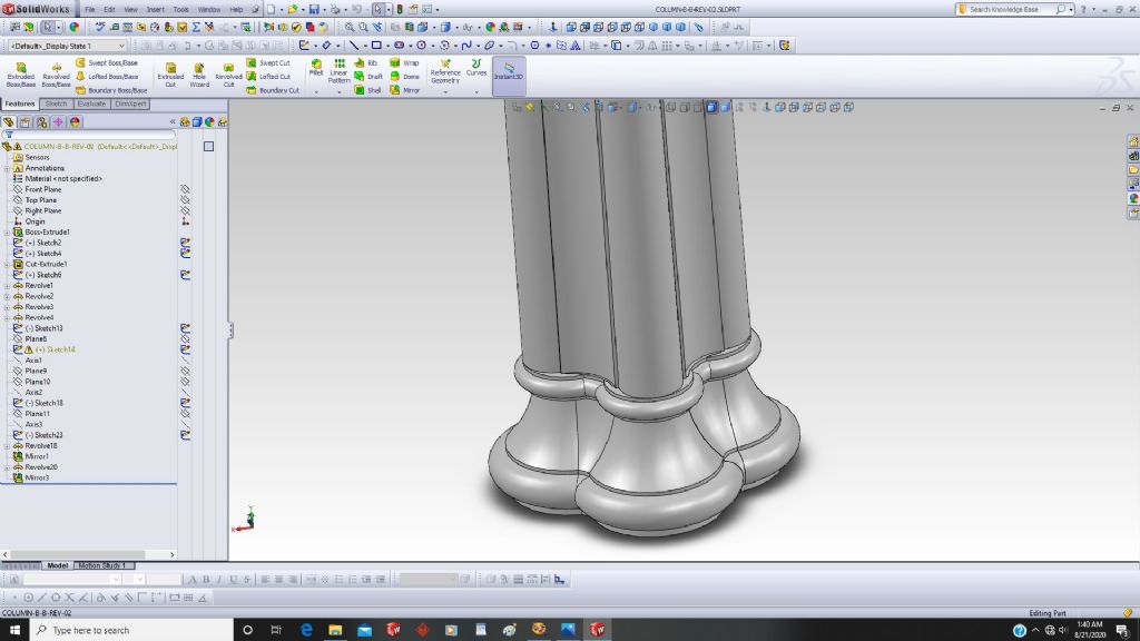
      The columns actually taper as they go up, like an ancient temple column, and so that was a challenge to get the flutes to act correctly.


      Edited By PatJ on 03/05/2022 06:32:35

      Edited By JasonB on 03/05/2022 07:35:07

      Advert
      #21378
      PatJ
      Participant
        @patj87806
        #596780
        PatJ
        Participant
          @patj87806

          Some of the drawings were missing, and some of the drawings had incorrect information on them, so I had to fill in the missing pieces (still working on that), and correct the things that were wrong.

          The engine is from the Gunboat Mississippi, 1840, which had two of these engines, and sidewheels.

          Luckily the Mississippi engine is very close to the Pacific engine, and designed by the same individual.


          steam-boat-pacific.jpg


          image24 (12).jpg

          Edited By PatJ on 03/05/2022 06:56:21

          #596781
          PatJ
          Participant
            @patj87806

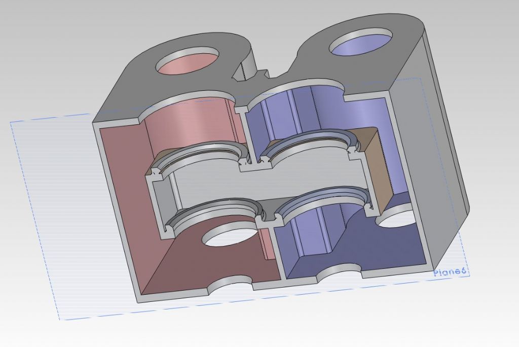
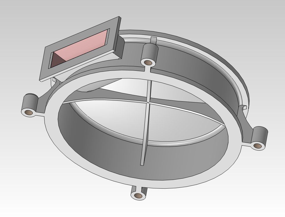
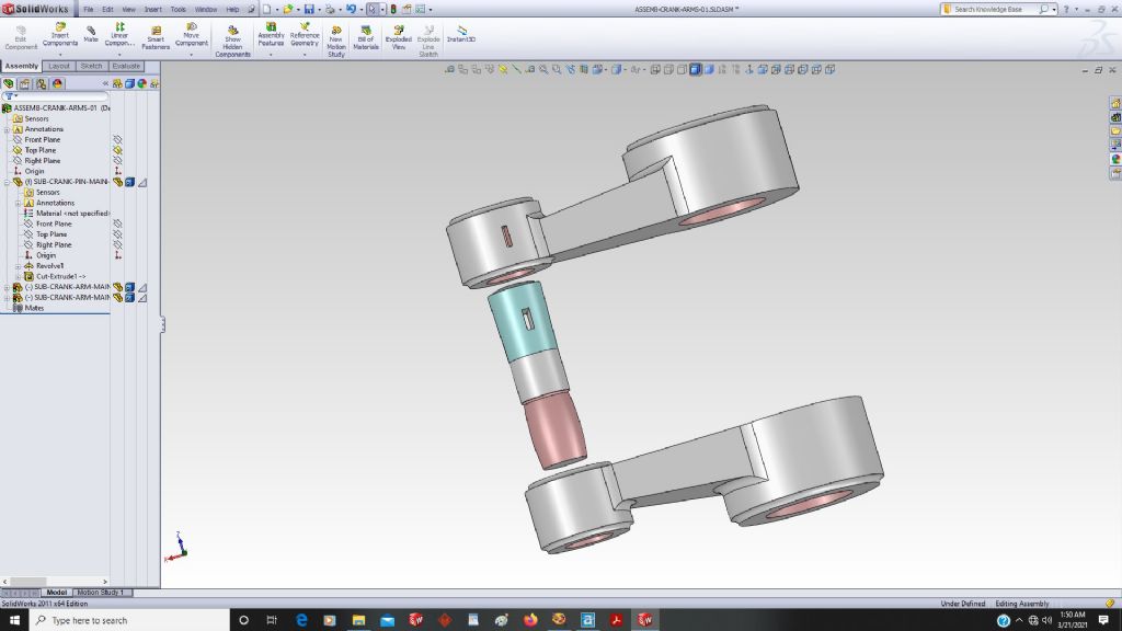
            My intent was/is to make 3D models that match the original design exactly (minus the errors that were in the original drawings). That has taken a lot of time, and a lot of discovery, and there are many subtle features in an old beam design, such as the crank pin only being fixed on one side, and have a ball on the other side that is not fixes (in case a wave hit a paddlewheel on one side, it would not shear the crank pin).

            I have made pretty good progress on this engine, but still have much to do.

            steam-chest-lower-10.jpg

            lower-cylinder-01.jpg

            image8 (20).jpg

            image77 (2).jpg

            image73 (2).jpg

            image68.jpg

            image67 (4).jpg

            image65 (4).jpg

            image58 (5).jpg

            image5 (3).jpg

            image44 (3).jpg

            image41.jpg

            image333-3.jpg

            image25 (2).jpg

            image22 (2).jpg

            image21 (7).jpg

            image14 (8).jpg

            image10 (6).jpg

            image24 (12).jpg

            #596782
            JasonB
            Moderator
              @jasonb

              That layout of engine is usually called a "side lever" with beam being kept for engines where the beam is at the top.

              #596783
              PatJ
              Participant
                @patj87806

                A few more screen captures.

                image20 (2).jpg

                image31 (9).jpg


                image34 (5).jpg

                image37 (11).jpg

                image47 (6).jpg

                image63 (5).jpg


                Edited By PatJ on 03/05/2022 07:28:20

                #596784
                PatJ
                Participant
                  @patj87806

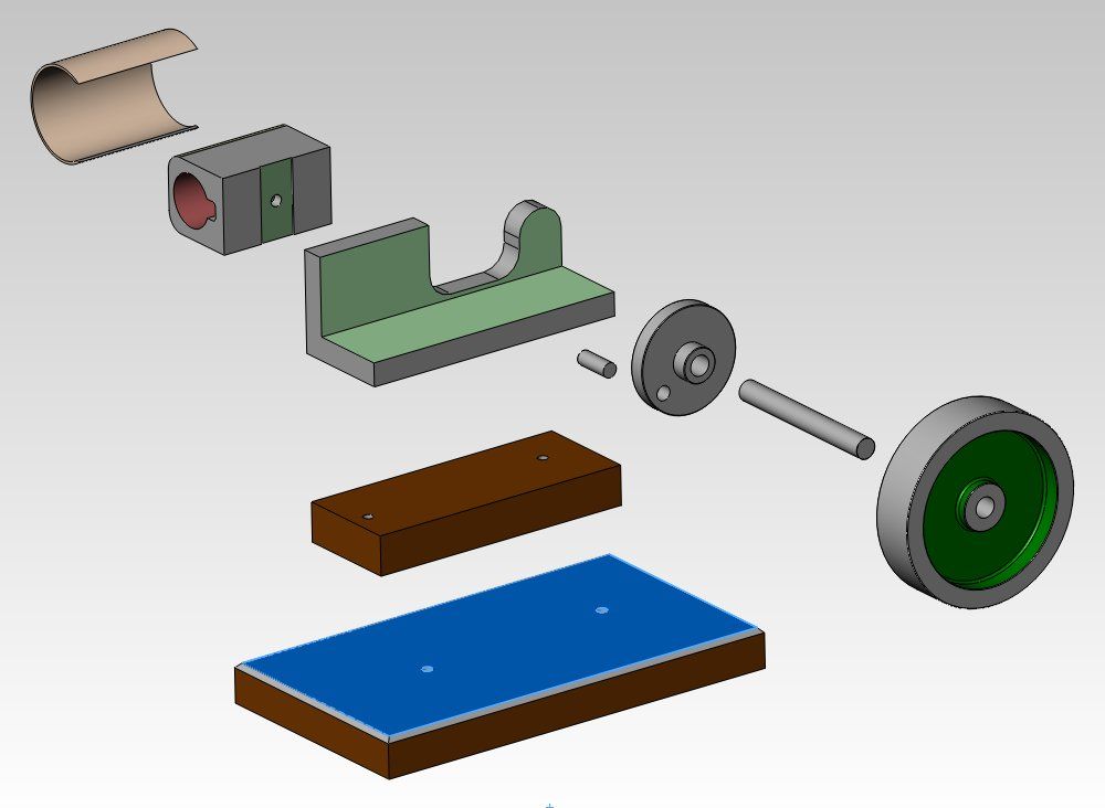
                  The first engine I recall modeling in 3D a few years ago was a barstock build of my dad's, and I recall struggling to create 3D parts for this engine. At the time, these models seemed pretty complex and challenging.

                  With each engine that I modeled, I got better at modeling, and so you can see where things can go if you work at learning 3D.

                  That is the challenge; make something in 3D, no matter how simple, then increase the complexity with each part that you model. Each step mastered becomes another tool in your 3D modeling toolkit.

                  Before you know it, it is Beam Engine time !

                  rframe-rev02-14.jpg

                  assembly-06.jpg

                  exploded-view.jpg

                  #596785
                  PatJ
                  Participant
                    @patj87806
                    Posted by JasonB on 03/05/2022 07:20:43:

                    That layout of engine is usually called a "side lever" with beam being kept for engines where the beam is at the top.

                    Yes, I completely forgot about that.

                    Such is my brain fog these days from too many work projects and too little time.

                    Perhaps you could change the heading to "Side Lever"; I don't see an option to change that.

                    .

                    Edited By PatJ on 03/05/2022 07:31:47

                    #596788
                    Michael Gilligan
                    Participant
                      @michaelgilligan61133
                      Posted by PatJ on 03/05/2022 06:31:47:

                      […]

                      The columns actually taper as they go up, like an ancient temple column, and so that was a challenge to get the flutes to act correctly.

                      .

                      Wonderful work, Pat … but your observation prompts a question

                      Do the original columns only taper, or do they have entasis ?

                      On a small model it would probably not be relevant [or even detectable], but at full size it might put the engine in a class above the rest.

                      MichaelG.

                      #596789
                      PatJ
                      Participant
                        @patj87806

                        I had to pull out the dictionary on that one.

                        I inserted the sheet below into CAD, and made sure it was level, and then drew lines up either side of the columns.

                        It appears that the columns have a linear taper; at least that is what it looks like to me.

                        This is the original 1840 sheet.

                        There is a great deal of artwork in the old engine designs.


                        rsheet-08-frame.jpg

                        Edited By PatJ on 03/05/2022 09:05:37

                        #596791
                        Michael Gilligan
                        Participant
                          @michaelgilligan61133

                          Thanks for checking, Pat yes

                          MichaelG.

                          #596799
                          SillyOldDuffer
                          Moderator
                            @sillyoldduffer
                            Posted by PatJ on 03/05/2022 09:04:53:…

                            It appears that the columns have a linear taper; at least that is what it looks like to me.

                            This is the original 1840 sheet.

                            There is a great deal of artwork in the old engine designs.

                            rsheet-08-frame.jpg

                            Pat's thread was read as a breakfast treat here! I do enjoy engineering drawings, whether the draughtsman uses CAD or pen and paper!

                            Pat's 1840 engine clearly imitates the architectural style of the day which was Gothic. The drawing above could almost be part of a cathedral or the Palace of Westminster, rebuilt after the original burned down in 1834:

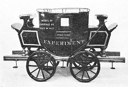
                            The architectural influence in Pat's 1840 drawing made me wonder where early draughtsmen came from. Before mechanical engineering drawing became a big thing, I guess technical drawing methods and skills came from architects, who would tend to transfer what they knew worked OK on buildings to engines. In the same way, early railway carriages were clearly copied from a stage-coach:

                            Later draughtsmen would have specialised in engineering drawings from the outset and become much more savvy about practical design: efficient function, reliability, and keeping manufacturing and maintenance costs down.

                            Pioneers have to do seriously clever stuff. We really do stand on the shoulders of giants.

                            Dave

                            #596879
                            PatJ
                            Participant
                              @patj87806

                              An interesting backstory on this engine design is that it was designed by Charles Copeland, who was either a contractor, or worked for the US Navy.

                              In looking at the Mississippi drawings, I noticed an incredible gaffe, which was that the crank arms were drawn both facing the same direction. No competent engineering designer would ever make such an obvious blunder.

                              So I assumed that this must be Copeland's first attempt at a steam engine for a Naval vessel (I think this was the first steam powered Naval vessel design for the US), and I assumed (falsely) that this would also be Copeland's last engine design, since he clearly did not know what he was doing with the Mississippi design.

                              I found other errors in the Copeland drawings, and in general, they are good examples of very poor drafting and engineering design.

                              Further research indicated that Copeland went on to design other ship engines, apparently very successfully, and sophisticated designs, and so I guess it was a learning process for him.

                              And as a comparison, I found a set of French side-level engine drawings, also created in 1840, and the French drawings indicate a very refined and complete design, with exceptionally clear and concise drawings.

                              The Mississippi engines are so close the French design that I have to suspect that Copeland researched other engine designs, and basically copied them to the best of his ability (which was very poor ability).

                              I tend to forget how primitive engineering design and manufacturing was in the US in 1840.

                              England was king of the world as far as industrial design in the 1800's, although the French design from 1840 is very respectable. Charles Porter mentions in his book "Engineering Reminisces" that the only way to make a decent steam engine in the US was to order all of the tooling and measuring instruments from England.

                              To this day I still find and buy some superb products from England, such as a large paper cutter I bought recently.

                              Manufacturing seems to have vacated the US these days, but that is another story that we won't get into.

                              I am not up on architectural terms, but gothic seems to describe the Mississippi engine design well.

                              It is amazing how much effort went into the cosmetics of these old engines.

                              Later engine designs are devoid of these striking and remarkable visual features, and one has to lament that something has been lost over time.

                              .


                              Edited By PatJ on 03/05/2022 22:43:04

                              #596882
                              PatJ
                              Participant
                                @patj87806

                                The proportions on the Mississippi engines are enormous.

                                As I recall, the cylinder bore was 8 or 10 feet.

                                The engines were said to be slow moving and reliable, and would function well even when in worn condition.

                                The Mississippi had a very successful sailing career, and I guess set the stage for steam Naval power in the US.

                                As I understand it, Copeland basically took a large sailing vessel, and shoehorned two large engines and associated boilers and coal bunkers into it.

                                The fit is rather tight.

                                As I understand it, many in the US Navy were against steam power, because while they did not object to being shot and killed by cannon fire, being scalded/burned alive by boiling water and steam was a bridge too far.

                                .

                                Edited By PatJ on 03/05/2022 22:52:31

                                #596892
                                SillyOldDuffer
                                Moderator
                                  @sillyoldduffer

                                  Posted by PatJ on 03/05/2022 22:48:43:

                                  As I understand it, many in the US Navy were against steam power, because while they did not object to being shot and killed by cannon fire, being scalded/burned alive by boiling water and steam was a bridge too far.

                                  My bedtime reading at the moment is the 'Personal Memoirs of U S Grant', who mentions:

                                  'My regiment lost four commissioned officers, all senior to me, by steamboat explosions during the Mexican war. The Mexicans were not so discriminating. They sometimes picked off my juniors.'

                                  smiley

                                  After the Mexican War of 1846-1848 the US acquired California, New Mexico and Texas.

                                  Dave

                                  #597090
                                  Tim Stevens
                                  Participant
                                    @timstevens64731

                                    Interesting. I think there is another reason for the first railway carriages to look just like road carriages. This is the problem of public acceptance. People will not travel on or in, or purchase, or have in the drives (etc) a vehicle which is totally unfamiliar.

                                    Look at the electric cars we are blessed with today. Even those which are not spitting images of standard models have dummy radiators.

                                    Perhaps the best example I know is the Suzuki wankel-engined motorcycle of the late 1970s. The designers had fun with it, making it obviously new, and related to a rotary engine, with spherical lamps and flashers etc. As a style exercise, bang on – but Joe Public did not like it at all. In six months it was toned down to look much more like the bikes were knew, and people bought them.

                                    Remember that the first railway carriages had to appeal, not 'merely' to the travelling public, but to the railway shareholders – not the most adventurous folk …

                                    Cheers, Tim

                                  Viewing 16 posts - 1 through 16 (of 16 total)
                                  • Please log in to reply to this topic. Registering is free and easy using the links on the menu at the top of this page.

                                  Advert

                                  Latest Replies

                                  Viewing 25 topics - 1 through 25 (of 25 total)
                                  Viewing 25 topics - 1 through 25 (of 25 total)

                                  View full reply list.

                                  Advert

                                  Newsletter Sign-up