Olds Type “R” – Hit and Miss Engine

Advert

Olds Type “R” – Hit and Miss Engine

Home Forums CAD – Technical drawing & design Olds Type “R” – Hit and Miss Engine

Viewing 17 posts - 1 through 17 (of 17 total)
  • Author
    Posts
  • #595184
    PatJ
    Participant
      @patj87806

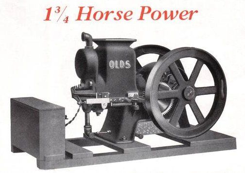
      I ran across some photos of a scale model of an Olds Type "R" hit and miss engine, perhaps 1.5 or 1.75 hp, and I really like the looks of this engine.

      It is produced in 1/2 scale (subject to castings availability).

      At one time it was available as a 1/2 scale casting kit labled "Briesch Olds".

      In researching this engine, apparently the patterns changed hands a few times in auction, and it appears that the 1/2 scale Olds patterns have been either lost or set aside under a lot of dust in someone's garage or barn.

      I inquired around as to whether there were any 1/2 scale Briesch Olds casting kits or drawings available, and apparently those who have the drawings don't want to share them for copyright reasons, which I fully understand and appreciate.

      So what is a person to do who would like to make a 1/2 scale Olds Type "R"?

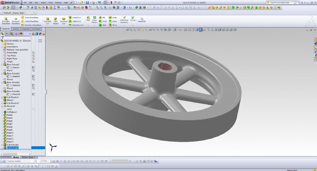
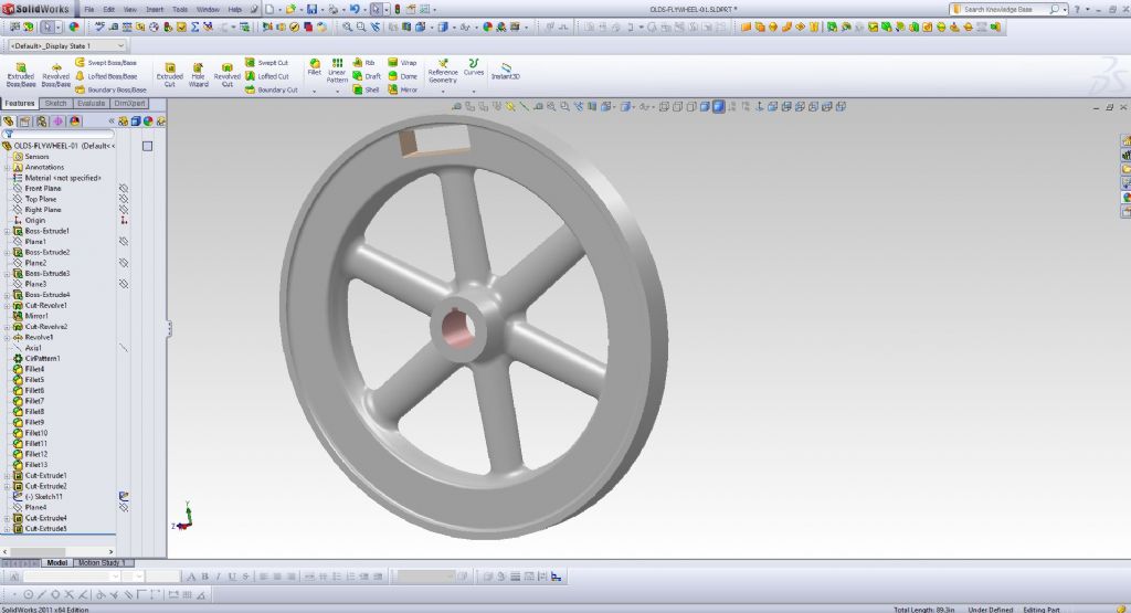
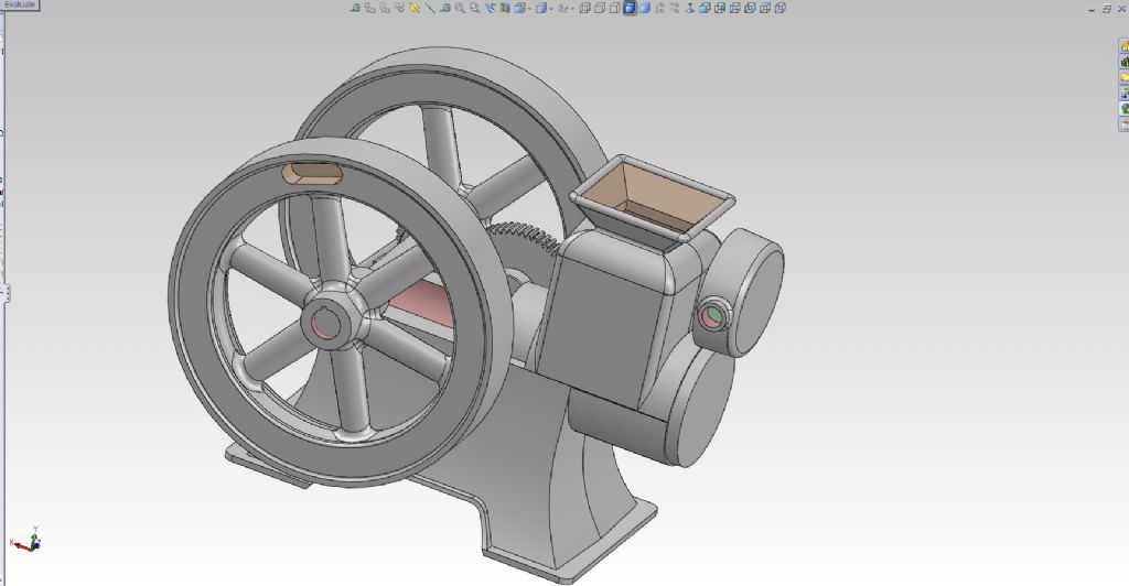
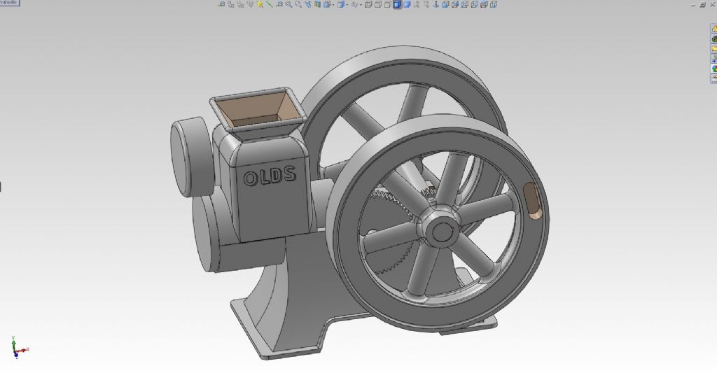
      Well, all it takes is a few good photos, and one can recreate many of the old engines. This particular engine is not too terribly complicated, luckily, and so I am on a Monty-Python-type holy quest to recreate the Olds Type "R" in 3D modeling, print patterns, and then make iron castings at a scale slightly larger than 1/2 scale (so that the flywheel diameter is an even 10&quot.

      Perhaps a good exercise in 3D modeling.

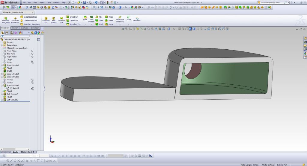
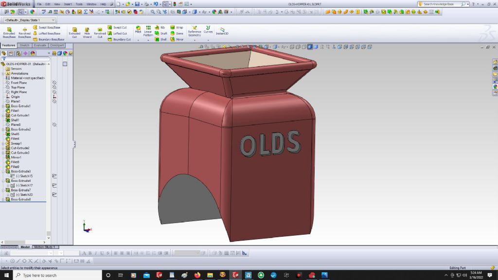
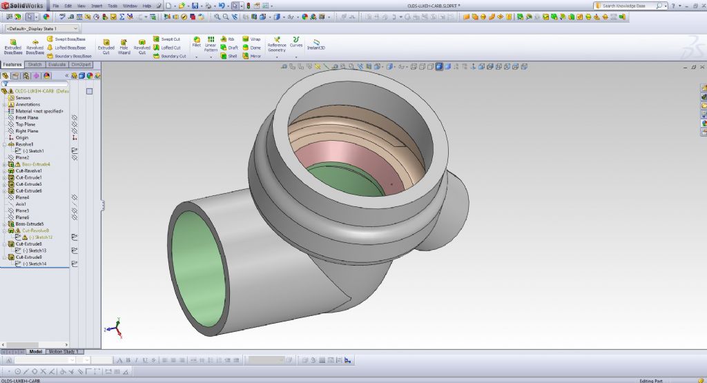
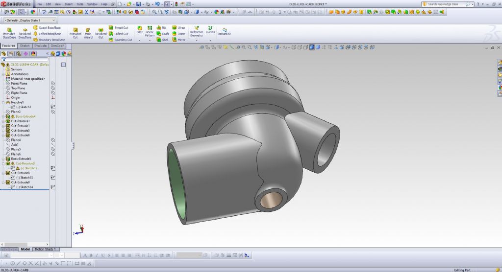
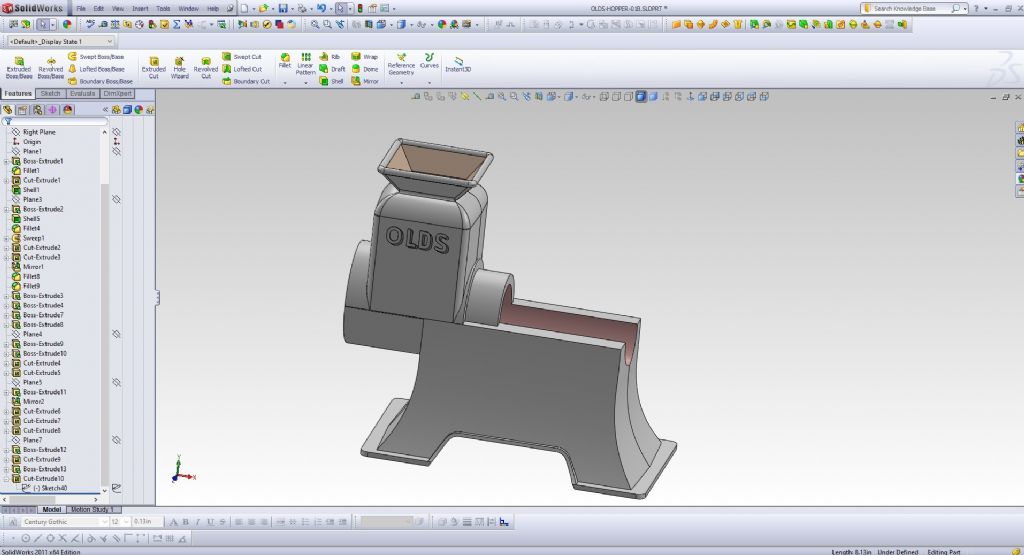
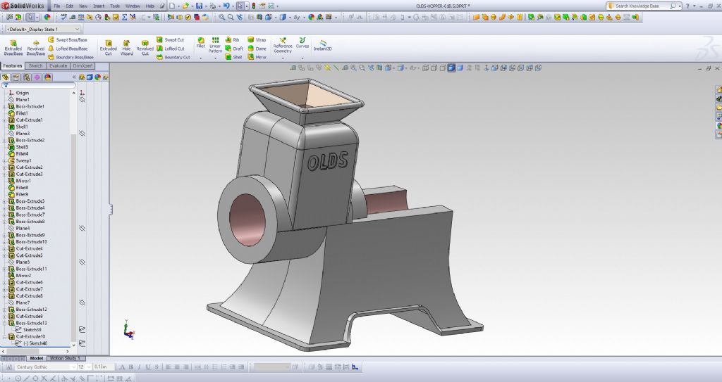
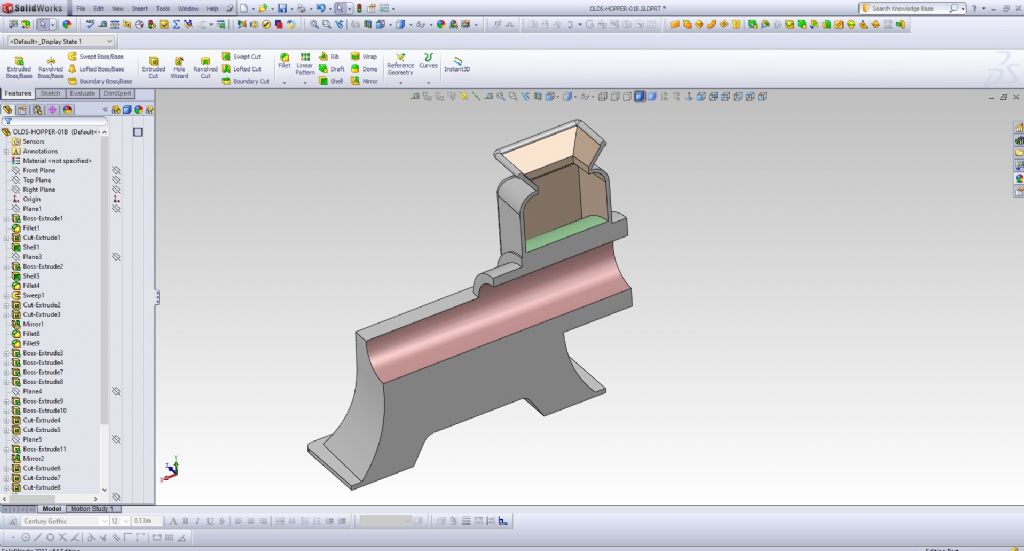
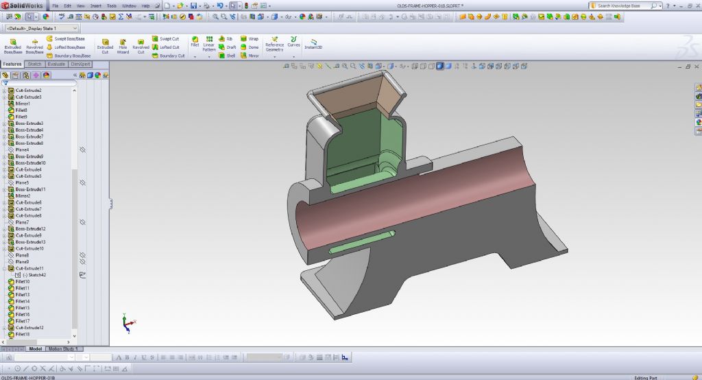
      All of the 3D models for this engine have been created with the appropriate draft angle, which makes them a bit more tedious and difficult to handle, but well worth it in the end whey one is trying to pull the patterns from the sand.

      So far I am pleased with the progress I have made, working on and off over about 1 week's time.

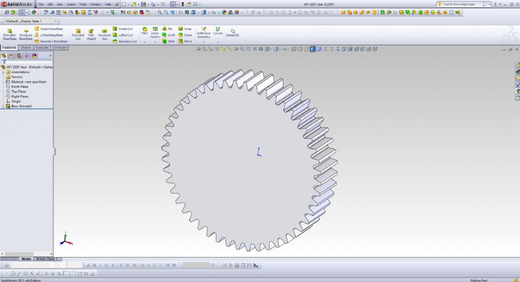
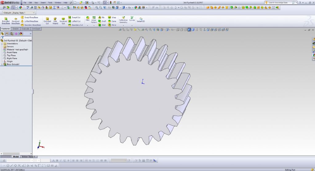
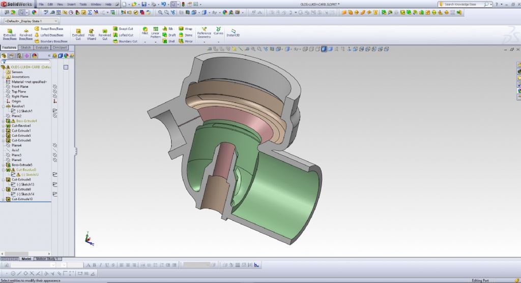
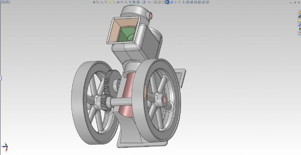
      Here are a few screen captures of the 3D models.

      Advert
      #21376
      PatJ
      Participant
        @patj87806
        #595186
        PatJ
        Participant
          @patj87806

          Screencaps.

          image1014.jpg

          image1022.jpg

          image1083.jpg

          image1090.jpg

          image333.jpg

          image334.jpg

          image34.jpg

          image38.jpg

          image41.jpg

          image42.jpg

          image44.jpg

          image55.jpg

          image3.jpg

          image111.jpg

          image1.jpg

          #595187
          PatJ
          Participant
            @patj87806

            I did get the water jacket added.


            image18.jpg

            Edited By PatJ on 20/04/2022 12:07:44

            #595193
            Hopper
            Participant
              @hopper

              Brilliant bit of reverse engineering. Watching with interest.

              It's a shame some people get hung up on copyright issues on ancient drawings that are out of print and most likely nobody cares about. Single copies for non-commercial personal research use are most often perfectly legit but there is no convincing some people of that. Subsequently, a lot of old stuff is being lost without trace, as you say gathering dust under someone's bench, to be thrown on the tip by his family when he drops off the twig.

              So keep up the good work reverse engineering and preserving a piece of engineering history!

              #595197
              David-Clark 1
              Participant
                @david-clark1

                Watching. This is another very interesting thread. I believe copyright (patent) lasts no more than 20 years so copyright on these old engines is out of date.

                I would have thought a particular scale would be more important than standardising the flywheel diameter?

                #595199
                PatJ
                Participant
                  @patj87806

                  Thanks for the kind comments.

                  I have to agree with the fact that a lot of old model engine designs are disappearing.

                  All I can do is work diligently to reverse that trend.

                  My thoughts are if someone made the drawings originally from looking at an old engine, then someone else can do the same thing, and recreate the engine again. Many assume it can't be done, and at one time I assumed it could not be done either, but I have since learned how to do it, and have successfully recreated an engine from three photos.

                  I am not sure about the exact copyright dates for engine drawings, but my plan is to start from a clean slate, and thus avoid any and all future copyright issues.

                  I have always been a bit unorthodox in my engine scales, and have never felt like I need to adhere to any particular scale factor. Call me crazy, but that is my approach.

                  The good thing about creating a 3D model though is that they can be 3D printed at any scale, and so people can create whatever size scale model they desire.

                  I hope one day to share the 3D model files for this engine, so that others can perhaps build it, and it won't be lost forever.

                  .

                  Edited By PatJ on 20/04/2022 14:00:37

                  #595202
                  JasonB
                  Moderator
                    @jasonb

                    Well a sensible scale has never stopped the Loco boysdevil

                    Plus many a scale for stationary engines was chosen so you could get the flywheel into the gap of a Myford and that is why there are so many of the old designs with flywheels all around about 9" diameter

                    #595204
                    Bruce Voelkerding
                    Participant
                      @brucevoelkerding91659

                      I have not built any internal combustion engines, but I would think making the Cylinder as a Sleeve or a Flanged Sleeve would make the casting of the Main Body much easier. If the Flange were on the Head side it could be sandwiched between the Head and Body with the Head Bolts. Leakage at the opposite end could be dealt with some sort of Sealant.

                      This removes the interrupted cut as you try to machine the Cylinder Feature as shown. You will need to add clearance for the Crank Shaft at bottom dead center.

                      #595205
                      PatJ
                      Participant
                        @patj87806

                        The difference between the 1/2 scale 9" flywheels and 10" flywheels is pretty slight, and so I really don't have a problem with casting it with 9" flywheels.

                        At a glance, I doubt many would be able to distinguish between 9" and 10" flywheels.

                        One reason I go for the slightly larger size engines/odd scales is that they are much more forgiving to machine, and also my eyesight is not good these days, and it is easier to see and machine larger parts.

                        I would not really want to create two sets of 2D drawings, so I guess will go with 1/2 scale for the Olds.

                        Generally speaking though, I don't adhere to a typical scale factor, but often let the piston diameter drive the overall engine dimensions. I have standardized on a 2" bore minimum for most engine designs I am working on.

                        .

                        #595206
                        PatJ
                        Participant
                          @patj87806

                          I think JasonB posted a photo a while back of machining an engine bore using a boring bar in the lathe, with the engine crankcase bolted to the carriage.

                          That is how I would machine the bore.

                          The Detroit Diesels used sleeves very successfuly in their engines, and it makes rebuilding a snap, but my philosophy is to cast it as it was originally cast, for historic accuracy.

                          Many casting kits depart from historically accuracy, in order to simplify the design, but I can't bring myself to do this.

                          I guess that puts me in the obsessive-compulsive category, but I have to cast it like the original, so no sleeve.

                          .

                          #595207
                          PatJ
                          Participant
                            @patj87806

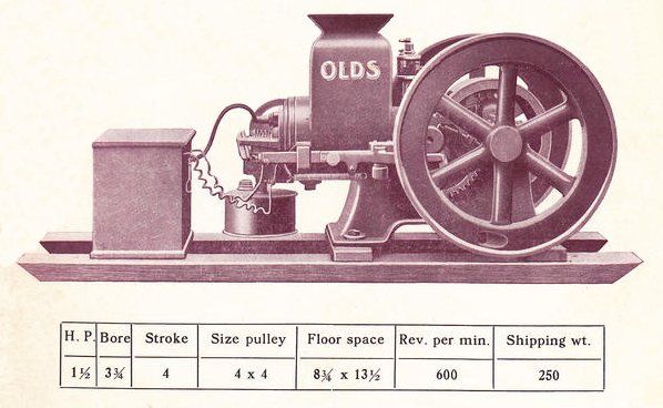
                            I purchased some old Olds brochures on ebay, and they gives a good idea of the model "R".

                            Olds apparently sold the rights to this engine to at least two other companies, or perhaps it got passed along, which are Seager, and Reliance.

                            This model was made by Reliance Engineering Company of Lansing Michigan, but it still has the "Olds" logo on the water hopper.

                            olds-reliance-engineering.jpg


                            Edited By PatJ on 20/04/2022 16:25:37

                            #595208
                            PatJ
                            Participant
                              @patj87806

                              Here is the Seager Olds Type "R".

                              Some slight differences from the Reliance Olds.

                              I am going more by the Reliance configuration, but not entirely.

                              To some extent, I am morphing the Seager with the Reliance design, which may be sort of a faux pas.

                              Oddly enough, the Reliance is listed at 1.75 hp, and the Seager is listed as 1.5 hp.


                              seager-olds.jpg


                              Edited By PatJ on 20/04/2022 16:30:17

                              #595212
                              JasonB
                              Moderator
                                @jasonb

                                I think just about all the hit and miss type engines I have built have all had the separate CI sleeve as Bruce suggests as in many case sit it not practical at our sizes to cast in the water spaces with complex cores. either due to the cores becoming very delicate or not being able to pour the iron into the small spaces around the cores without it cooling too quickly or not flowing.

                                Cost also comes into it for the casting kit engines as the added costs of complex cores would put them out of reach to many, OK if you have all the time in the world making one offs at home and can afford a few failures until you get a good pour but not if making a set of castings to a budget.

                                #595214
                                PatJ
                                Participant
                                  @patj87806

                                  For a model engine this size, I don't really see a need to have the water jacket extend under the cylinder.

                                  The problem with scaling down engines is that sometimes parts and pieces become too thin or small.

                                  And one more reason to make models as large as possible, so as to preserve as much detail as possible.

                                  I will have to look at how small the water jacket space becomes on a scale model, but if the space is too small, I would just eliminate it.

                                  The engine won't overheat if the water jacket is only on the top of the cylinder.

                                  I won't sleeve the cylinder, although no doubt that is an excellent option in many cases.

                                  No sleeve is just my preference.

                                  There is much that can be accomplished with resin-bound sand, but as Jason mentions, there are limits as to how far gray iron will flow in small spaces.

                                  You can generally get a complete fill on intricate work by adding phosphorus, but I never add phosphorus to my metal, but prefer to use untainted scrap iron from electric motor end bells.

                                  .


                                  Edited By PatJ on 20/04/2022 18:43:37

                                  #595216
                                  JasonB
                                  Moderator
                                    @jasonb

                                    That's an option with a hopper cooled engine even if some of the thermal movement of the cooler water going to the bottom and rising as it is heated will be lost.

                                    If the engine is a horizontal tank cooled then you do need the water space all around so the water will actually flow from the cold bottom of the tank up and around the cylinder and then out a pipe at the top and into the top of the tank to form the thermosyphon that makes the water flow.

                                    Same if it were a vertical you want the water all round so would need to core or sleeve. Think ball hopper Monitor, there is very little water contact if you just had the hopper at the top and no water down the sides of the cylinder

                                    #595303
                                    PatJ
                                    Participant
                                      @patj87806

                                      I think I would use knife gates on both sides of the hopper, and then have gates on either end of the cylinder too.

                                      The bore would have to be casts pretty thick in order for it to have a chance to fill; perhaps 3/8" thick walls or a little more. Omitting the bore core would cause too much shrinkage.

                                      I am not sure if a 1/4" thick water jacket core would hold up to iron temperatures, but it is possible.

                                      Some folks imbed a steel wire in thin cores to help them remain intact during the pour.

                                      Another approach would be to cast the cylinder thicker than normal, and drill long holes in from the head end down the sides of the cylinder, and let them join the water hopper via slots in the head.

                                      Thin cores are definitely a tricky thing to cast.

                                      The Speedy Twin passage cores used a lot of chaplets to hold them in place, and if you look at the top of a Speedy Twin, you can often see the tops of the chaplets imbedded in the cast iron.

                                      .

                                    Viewing 17 posts - 1 through 17 (of 17 total)
                                    • Please log in to reply to this topic. Registering is free and easy using the links on the menu at the top of this page.

                                    Advert

                                    Latest Replies

                                    Viewing 25 topics - 1 through 25 (of 25 total)
                                    Viewing 25 topics - 1 through 25 (of 25 total)

                                    View full reply list.

                                    Advert

                                    Newsletter Sign-up