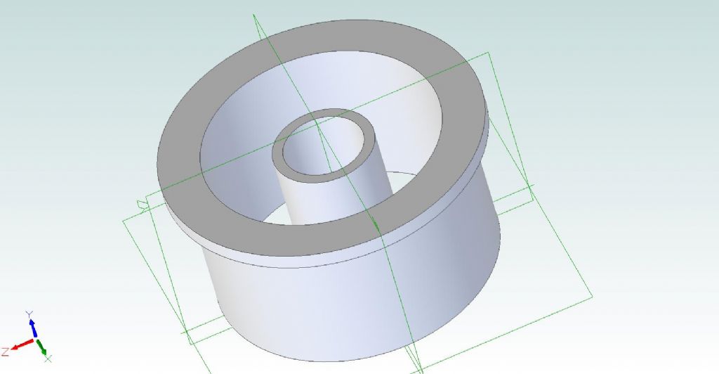
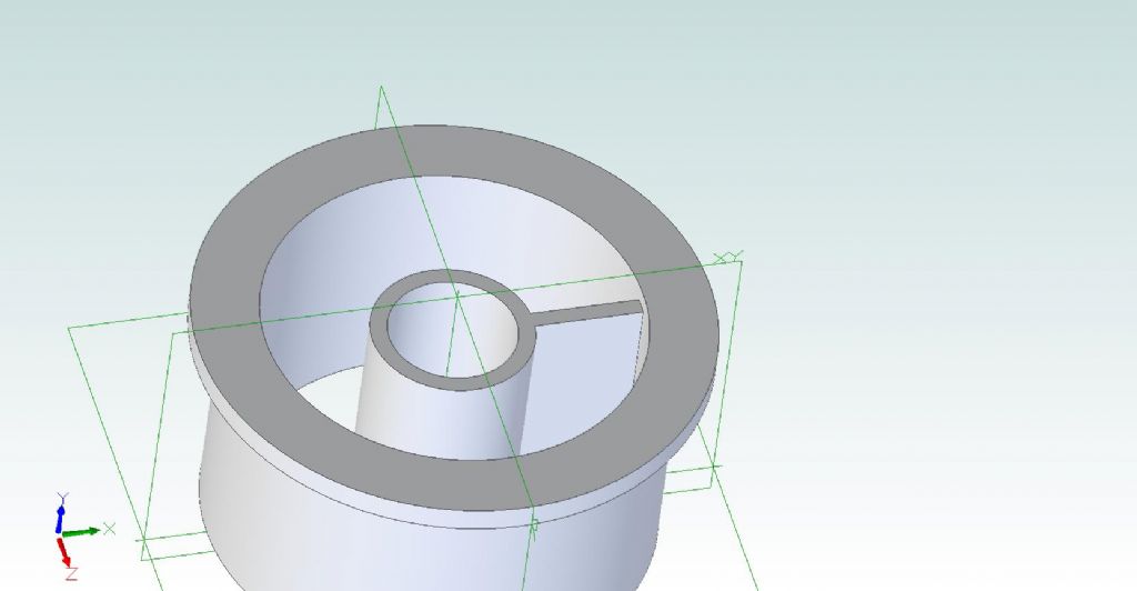
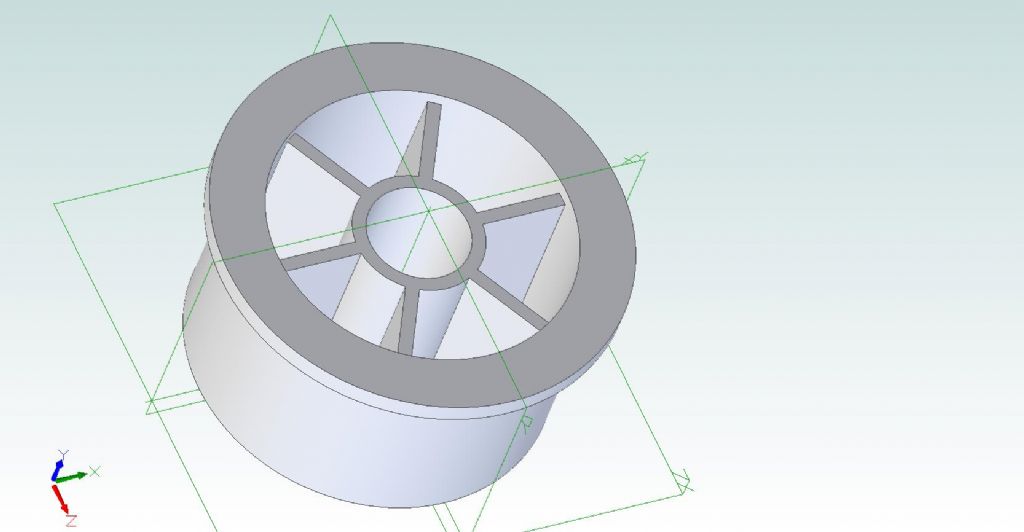
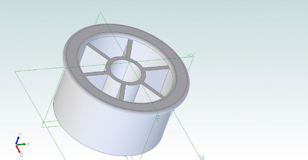
3D-CAD Package Shootout – Cotton Reel Example

Advert

3D-CAD Package Shootout – Cotton Reel Example

Home Forums CAD – Technical drawing & design 3D-CAD Package Shootout – Cotton Reel Example

Viewing 25 posts - 1 through 25 (of 113 total)
  • Author
    Posts
  • #593975
    SillyOldDuffer
    Moderator
      @sillyoldduffer

      All too often a question about choosing 3D-CAD software descends into a confusing exchange of conflicting personal opinions, leaving no one the wiser! Name a package and some swear by it, while others swear at it.

      This thread asks CAD jockeys to show how their preferred product produces a the same common object. It's purpose is to show the steps necessary to go from a set of dimensions to a finished object. By keeping the object simple, we can concentrate on how each CAD package gets to the goal, and compare how they each do an actual job. I suggest this is more informative than a generalised discussion because newcomers will see the look and feel and how well or not they tune into the workflow. Let's demystify!

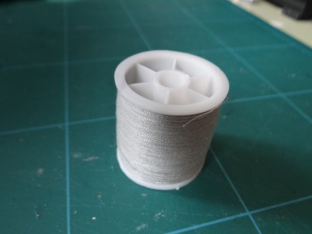
      The target is a plastic cotton reel, and the model could be 3D-printed in plastic or turned on a lathe. This is the original:

      dsc06582.jpg

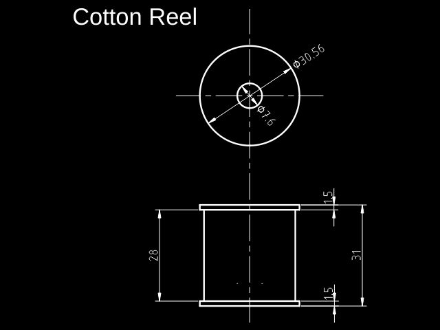
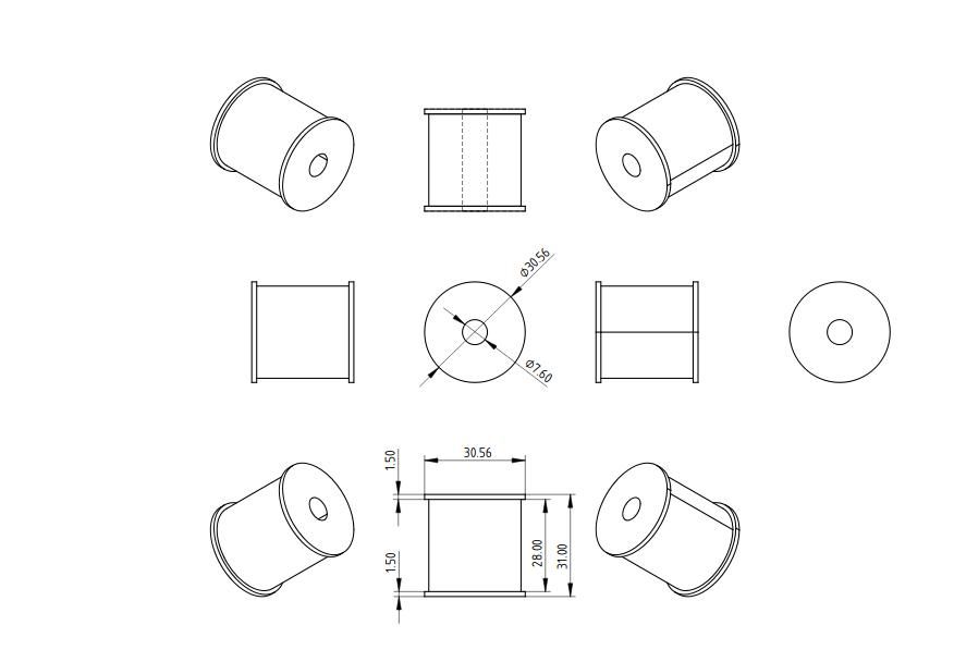
      Dimensions given in this drawing to no particular standard. QCAD used, back of envelope would do. Note the inner fins aren't called for, yet!

      cottonreel.jpg

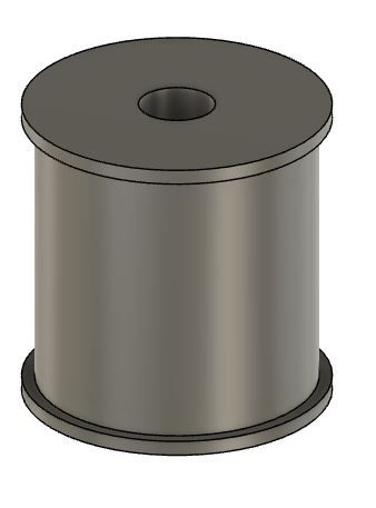
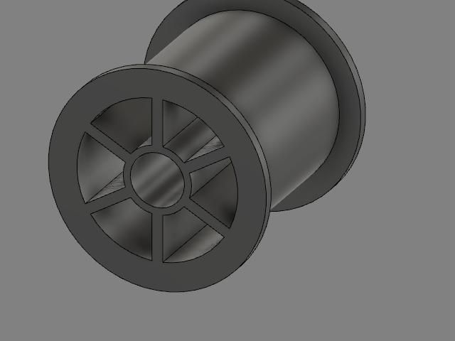
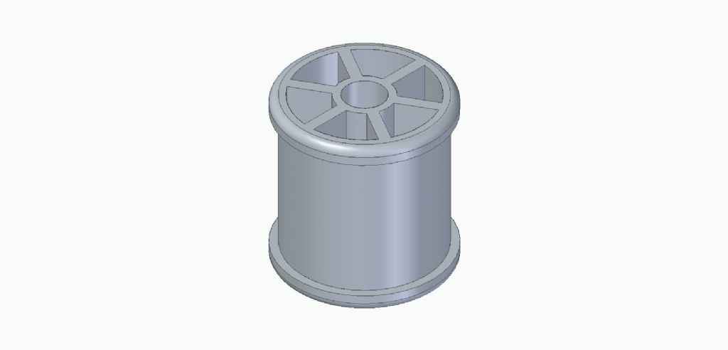
      The 3D model should look like this:

      f360cottonreel.jpg

      I'll start with FreeCAD;s Part Design Workbench, then do the same with Fusion360. As will be seen when both are published the workflow for producing a cotton-reel with these two is almost identical: the difference is mainly look and feel. If you can drive Part Design, you should be OK with F360 and vice versa, at least for simple objects. In practice, F360 is slightly slicker, but they take about the same time to do this job. I like them both.

      How to with FreeCAD next post.

      Dave

      Advert
      #21372
      SillyOldDuffer
      Moderator
        @sillyoldduffer
        #593979
        David Jupp
        Participant
          @davidjupp51506

          But there are many ways to produce that in all 3D CAD packages – there is no 'preferred method' for each CAD package, only preferred method of the person driving the system (and the limits of his/her knowledge of the system being used).

          Personally I might even tackle that slightly differently each time I try, as no one method jumps out at me as being simpler, faster, or more versatile.

          Could use revolutions, or Extrudes, or a mixture. Could do it all as additive, or could do some subtraction.

          I presume the 'pie slice shaped' hollows were omitted to keep things simple.

          Edited By David Jupp on 11/04/2022 14:44:50

          #593982
          Anonymous
            Posted by David Jupp on 11/04/2022 14:44:21:

            …there is no 'preferred method' for each CAD package…

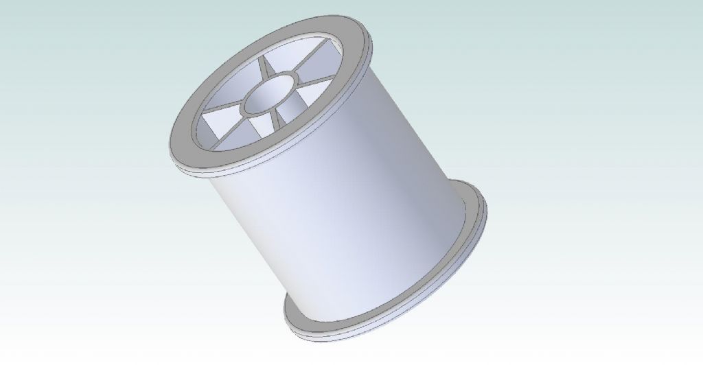
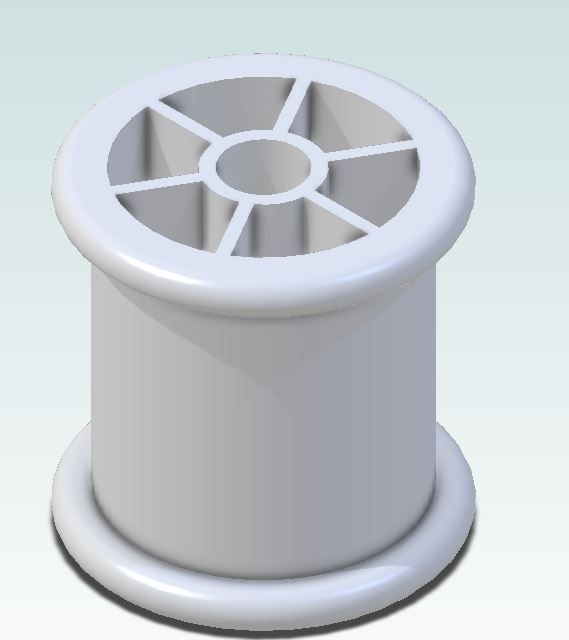
            Exactly; created this in five minutes in Alibre:

            cotton_reel.jpg

            I suspect my method is a bit involved, as it includes extrusions, revolutions, circular patterns and a mirror operation.

            Andrew

            #593985
            SillyOldDuffer
            Moderator
              @sillyoldduffer

              FreeCAD latest version is 0.20, but this is still a bit experimental guv, so I'm still using the current stable version v0.19.3 (Linux AppImage on Ubuntu 20.10). FreeCAD is available from here, installation should be straightforward.

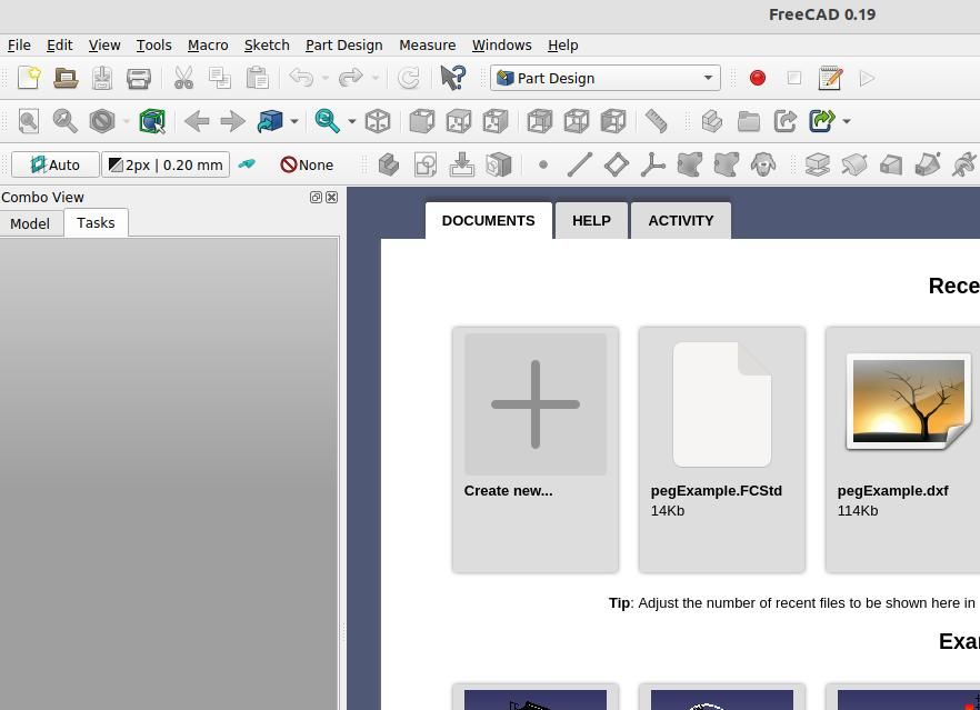
              Start the package by clicking a desktop icon or finding it with a search.

              freecadstart.jpg

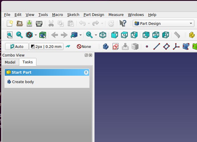
              Select 'Part Design' top right next to the red button and click on the big plus Create New Button, opening a 'Create Part Window:

              freecadcreatepart.jpg

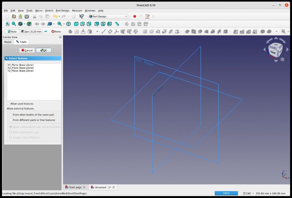
              Click on 'Start part', which opens a window asking which plane you want to draw in. Doesn't matter much, select XY:

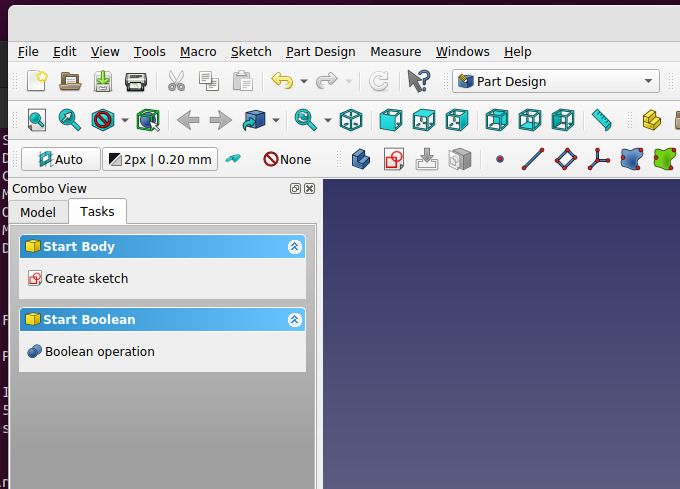
              freecadstartplane.jpgClick OK, and note the Task Bar on the right now allows new options:

              freecadcreatesketch.jpg

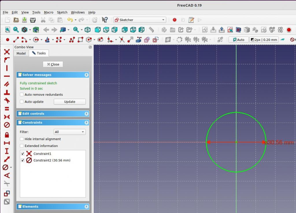
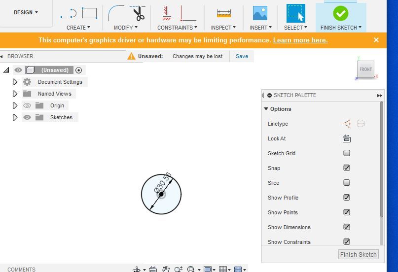
              Click Create Sketch to start the sketcher and draw a circle on the centre point with the circle tool (button with two red dots and a circle). Set the diameter to 30.56mm with the red ⌀ button. My screen has constraints vertically listed on the left, by default it's on top with the others.

              freecadbasecircle.jpg

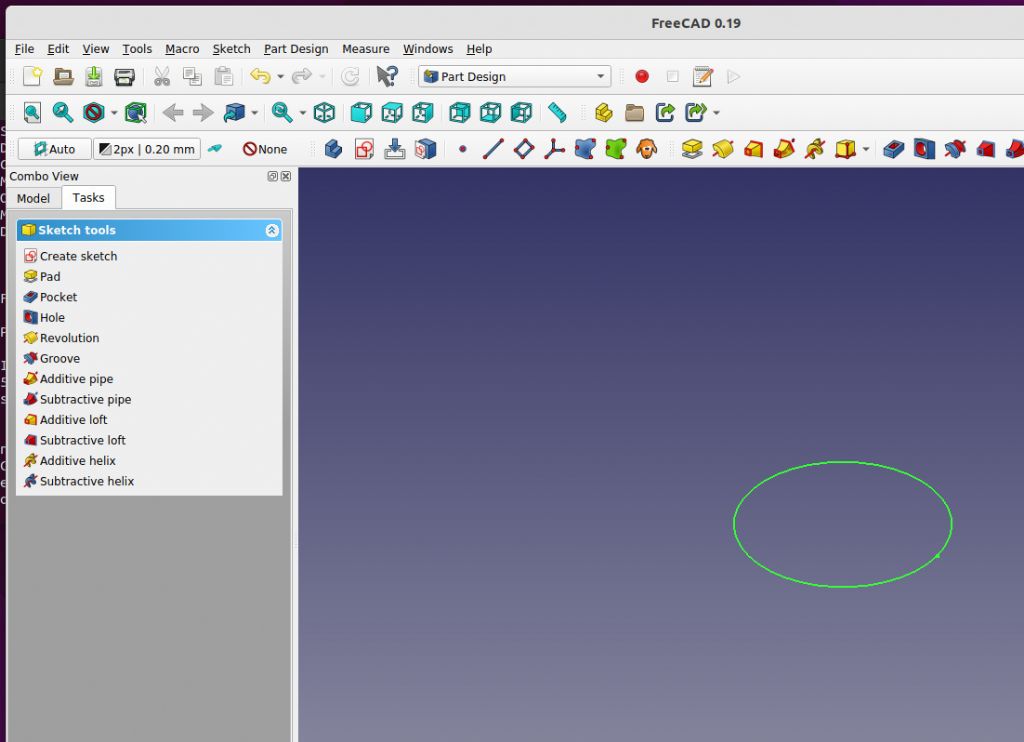
              The circle goes green to indicate it is fully constrained, i.e. it's centre coordinates and diameter are both fixed and won't move. Press the Close Button in the Task Pane to get a set of options that can operate on the circle.

              freecad1stpad.jpg

              More in next post

              Dave

              #593988
              Adrian Johnstone
              Participant
                @adrianjohnstone89946

                Hi Dave,

                I don't think that the diameter of the inner cylinder is specified in your drawing. Apologies if I am being dim. I'll use 28mm for no good reason

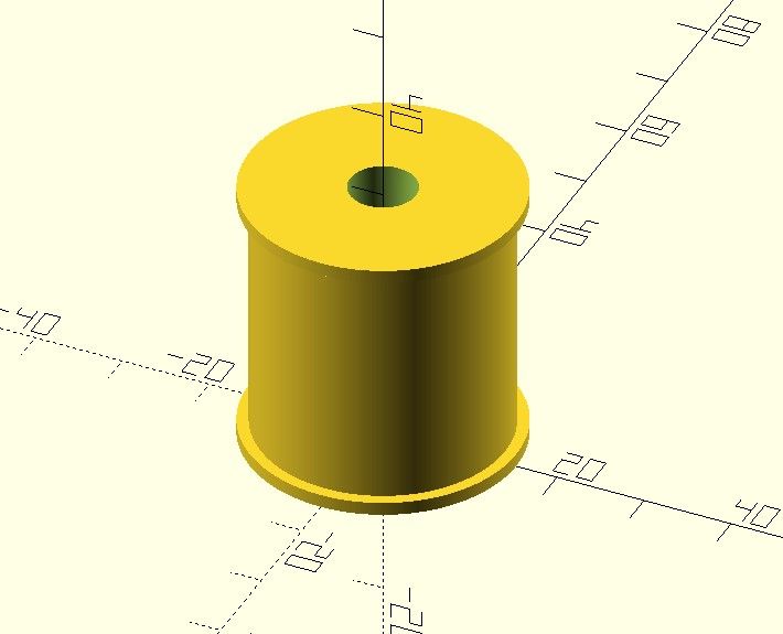
                Here it is in OpenSCAD, for the programmers in our midst (a small contingent here, perhaps).

                $fn=360; // Set number of segments in a circle
                difference(){
                union(){cylinder(1.5,15.28,15.28); cylinder(31,14,14); translate([0,0,29.5]) cylinder(1.5,15.28,15.28);}
                cylinder(32,2.8,3.8); // Remove the cental hole from the rest of the reel
                }

                Quick plug: if you are a railway modeller interested in 3D printing you will find lots of useful advice and CAD models in our Gauge One 3D circle forum which you can find here: **LINK** and you'll find a tutorial on OpenSCAD that I wrote for my students here: **LINK**

                Adrian

                #593991
                SillyOldDuffer
                Moderator
                  @sillyoldduffer

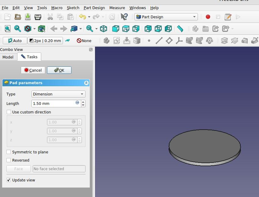
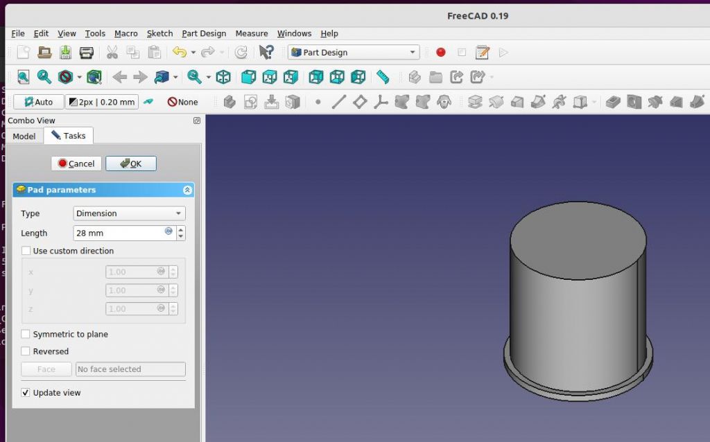
                  Click Pad and set the pad dimension to 1.5mm. Click to update the screen This pad creates the bottom of the cotton reel.

                  freecadbasepad.jpg

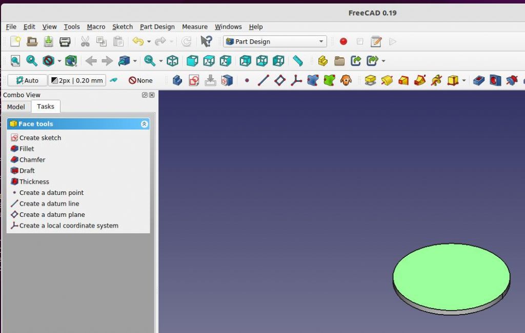
                  Click OK to close the Pad dialog, then select the top face of the cotton reel to select it. Should change colour:

                  freecadselecttopface.jpg

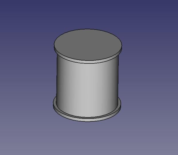
                  The option to Create Sketch has reappeared, so click on it allowing allowing a new sketch to be added to the object. Draw another circle and constrain it to 28.00mm Closing the sketch allows this one to be padded as well. Press pad and set the dimension to 28mm as well. OK the Pad, to reveal:

                  freecaddrumpad.jpg

                  In the same way, select the top face again by clicking it, create a new sketch with a circle diameter of 30.56mm, close the sketch, and Pad to 1.5mm:

                  freecadreelsanshole.jpg

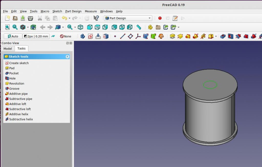
                  To add the hole, select the top face and create another sketch, this time making it 7.6mm diameter. Close the sketch:

                  freecadholesketch.jpg

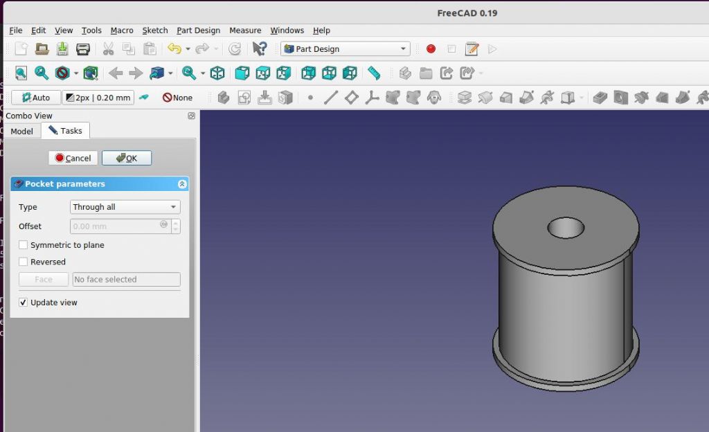
                  This time select the Pocket tool (Pad adds, Pocket subtracts). Set Type to 'Through All' and the hole is drilled.

                  freecadfinalhole.jpg

                  Closing Pocket leaves us with a completed model cotton reel. FreeCAD understands it to represent a solid and can use it to generate the usual 2D projections, to which the user can add dimensions, notes and sections:

                  freecadtechdraw.jpg

                  Or to export the object as a mesh or STL. These define the outer envelope of the solid and are used by other software to generate the additive g-code needed by a printer or the subtractive g-code needed by a CNC machine to cut metal.
                  Takes much longer to describe than do.

                  Fusion 360 next, after a nap and strong coffee. Delighted to see others submit the same job in Alibre, TurboCAD, MOI, Draftsight, Solidworks or any other favourite. Please don't cheat by doing it with one sketch and a rotate: I want to show how pad/extrude work with a succession of sketches.

                  Dave

                  #593993
                  Anonymous

                    A slap in the face with a wet fish is in order. smile

                    The original post asks how a preferred CAD package would create the given part. The latest post then says don't "cheat" by using revolve. The object is round so revolve is a logical operation; how is that cheating? I'd use two operations to create the "simple" shape; revolve followed by mirror.

                    Andrew

                    #593994
                    SillyOldDuffer
                    Moderator
                      @sillyoldduffer
                      Posted by Andrew Johnston on 11/04/2022 14:51:52:

                      Posted by David Jupp on 11/04/2022 14:44:21:

                      …there is no 'preferred method' for each CAD package…

                      Exactly; created this in five minutes in Alibre:

                      cotton_reel.jpg

                      I suspect my method is a bit involved, as it includes extrusions, revolutions, circular patterns and a mirror operation.

                      Andrew

                      Yes, I know Alibre is a big hitter, but can you explain step by step how you did it!

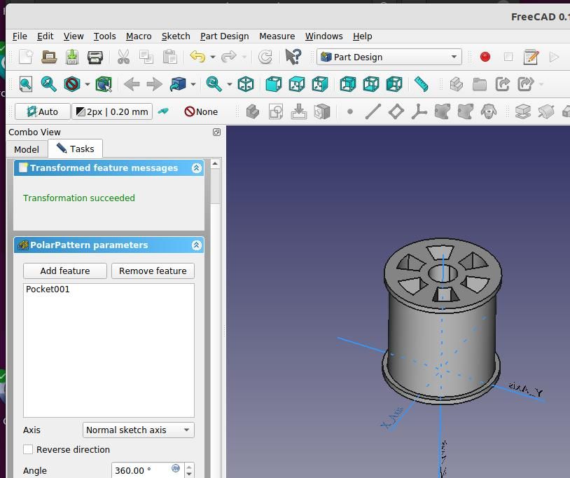
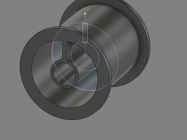
                      Trivial to do in FreeCAD (and F360), though I haven't done the cut out properly.

                      freecadpokedreel.jpg

                      Dave

                      #593996
                      SillyOldDuffer
                      Moderator
                        @sillyoldduffer
                        Posted by Adrian Johnstone on 11/04/2022 15:08:17:

                        Hi Dave,

                        I don't think that the diameter of the inner cylinder is specified in your drawing. Apologies if I am being dim. I'll use 28mm for no good reason

                        Here it is in OpenSCAD, for the programmers in our midst (a small contingent here, perhaps).

                        $fn=360; // Set number of segments in a circle
                        difference(){
                        union(){cylinder(1.5,15.28,15.28); cylinder(31,14,14); translate([0,0,29.5]) cylinder(1.5,15.28,15.28);}
                        cylinder(32,2.8,3.8); // Remove the cental hole from the rest of the reel
                        }

                        Quick plug: if you are a railway modeller interested in 3D printing you will find lots of useful advice and CAD models in our Gauge One 3D circle forum which you can find here: **LINK** and you'll find a tutorial on OpenSCAD that I wrote for my students here: **LINK**

                        Adrian

                        My mistake Adrian, it is 28mm.

                        blush

                        OpenSCAD is bundled with FreeCAD. I've never used it and will report back if I can get your code to run!

                        PS.  I guessed how it might be done and got errors:

                        16:06:57 Parser Loaded
                        16:06:57 Start Parser
                        16:06:57 Syntax error in input!
                        16:06:57 LexToken(ID,'$fn',1,0)
                        16:06:57 Syntax error in input!
                        16:06:57 LexToken(NUMBER,'1.5',2,79)
                        16:06:57 End Parser
                        16:06:57 None
                        16:06:57 End processing CSG file

                        Pretty sure this is due to me loading the program incorrectly.

                        Edited By SillyOldDuffer on 11/04/2022 16:20:48

                        #594003
                        JasonB
                        Moderator
                          @jasonb

                          Took me longer to snip and name the images then model the reel.

                          The spokes on mine are flush with the ends so I could have had one less operation if diameters and spokes done as one sketch but often it is better to split things up for easier editing.

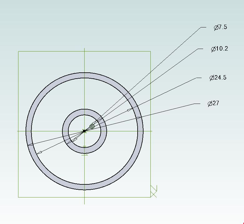
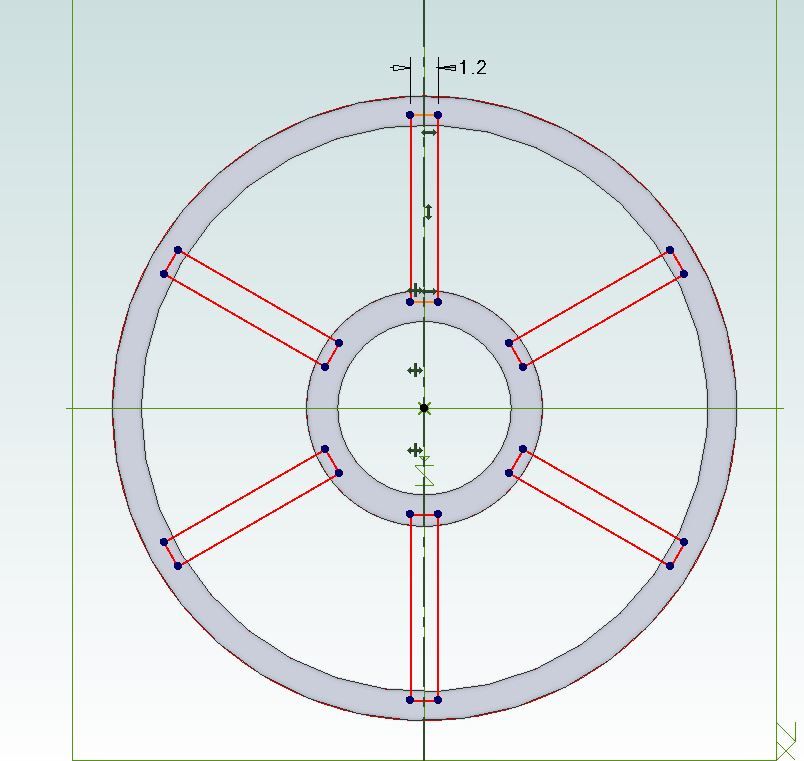
                          Start by drawing the inner ring and outer ring

                          reel2.jpg

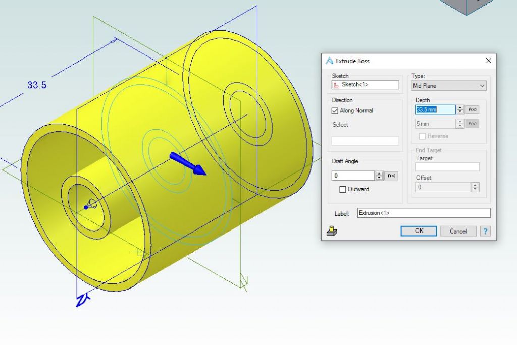
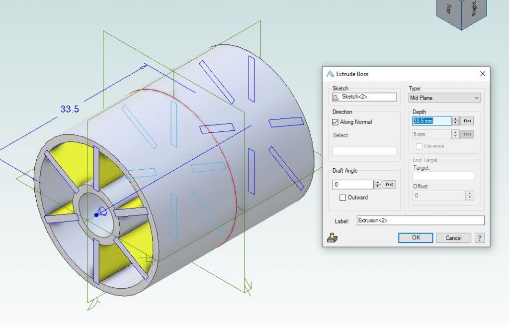
                          Extrude equally either side of the mid plane

                          reel3.jpg

                          Draw a single spoke set central to the vertical axis and then use circular pattern to add the other 5

                          reel4.jpg

                          Extrude spokes as before

                          reel5.jpg


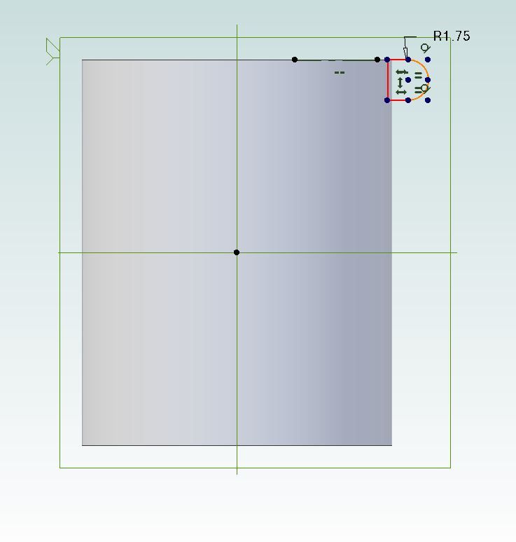
                          Draw the "D" section flange, top edge of flange set on same plane a stop of reel

                          reel6.jpg

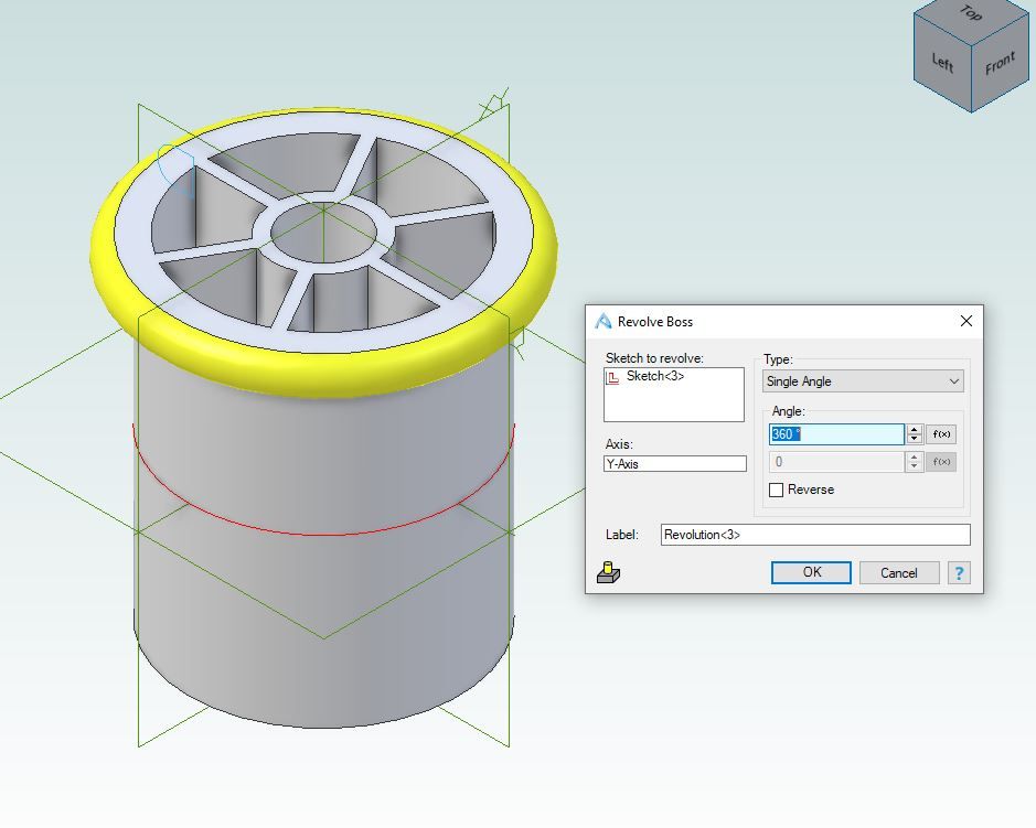
                          Rotate profile around central axis

                          reel7.jpg

                          Mirror to get one on the other end

                          reel8.jpg

                          Job done

                          reel9.jpg

                          Edited By JasonB on 11/04/2022 16:53:55

                          #594012
                          SillyOldDuffer
                          Moderator
                            @sillyoldduffer
                            Posted by JasonB on 11/04/2022 16:31:19:

                            Took me longer to snip and name the images then model the reel.

                            Job done

                            reel9.jpg

                            Like it! Is that Alibre?

                            #594024
                            JasonB
                            Moderator
                              @jasonb

                              Yes

                              #594029
                              Nick Wheeler
                              Participant
                                @nickwheeler

                                Here's Fusion, and there is no way I wouldn't use revolve:

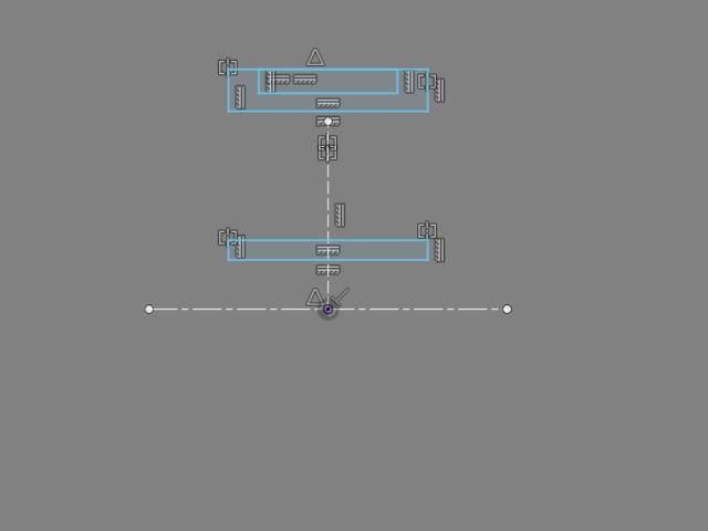
                                sketch1.jpg

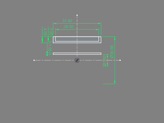
                                Draw a construction line vertical from the origin, and a centreline centred to the origin. Add three rectangles, constrained symmetrically around the construction line, and make the two longest lengths equal.

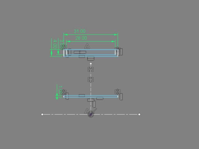
                                sketch2.jpg


                                Add the lengths

                                sketch3.jpg

                                And the diameters from the centreline so no radius calculations are needed

                                revolve.jpg

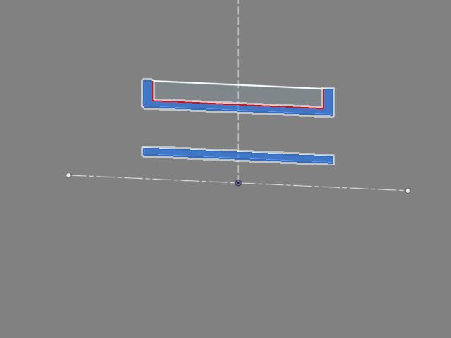
                                Finish the sketch, and select both profiles. Click on Revolve, and Fusion automatically picks up that the centreline is a suitable axis, which is why it was defined as such

                                body.jpg

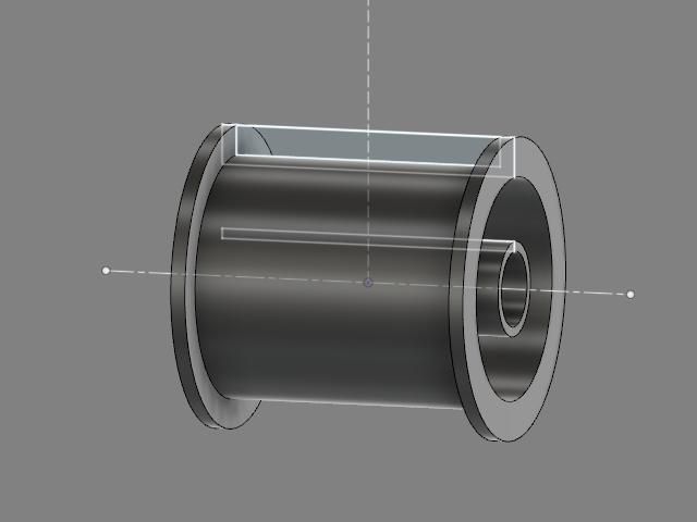
                                The resulting body, with the sketch still active

                                spokesketch.jpg

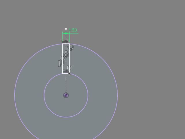
                                That's a new sketch, on the midplane; with the two diameters projected from the body, a vertical construction line from the origin, and a rectangle symmetrical to the line, tangent to the bigger circle, colinear to the small one and 1.5mm thick

                                extrudespoke.jpg


                                Extrude the spoke profile symmetrically to the end of the body, ensuring that it is a join.

                                6spokes.jpg

                                Use the spoke feature in a circular pattern, around the axis to create the other spokes.


                                Apparently, it will weigh 6grammes if made from ABS plastic….

                                Edited By Nicholas Wheeler 1 on 11/04/2022 18:31:51

                                #594032
                                blowlamp
                                Participant
                                  @blowlamp

                                  Similar to other examples, except I used the Inset feature as another way to make the ends.

                                  #594035
                                  SillyOldDuffer
                                  Moderator
                                    @sillyoldduffer

                                    This is Cotton Reel produced by Fusion360 using the same sequence of sketches and extrusions as I did with FreeCAD.

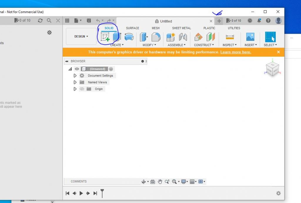
                                    First start the package. Then click the start sketch button circled ib blue below:

                                    f360start.jpg

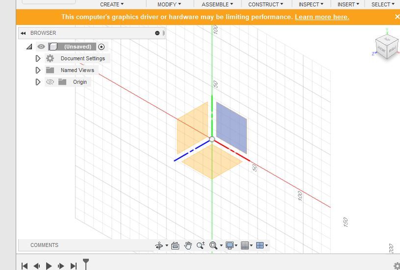
                                    Next screen, click on a pane to select the plane:

                                    f360plane.jpg

                                    That done, draw a circle and set its diameter to 30.56mm:

                                    f360basesketch.jpg

                                    Right clicking inside the circle opens a dialog with a Pull option. Pull's big blue arrow can extrude positively ('Pad&#39, or make a negative hole. Pull positively and make the dimension 28mm:
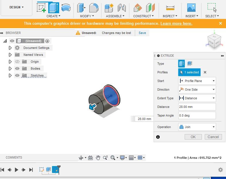
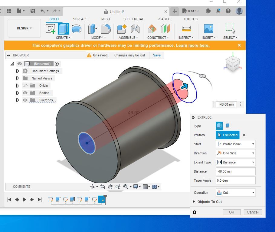
                                    f380drumpull.jpg

                                    Finish the sketch and open a new one on the end of the bobbin. Draw a circle of 30.56mm dia and pull by 1.5mm to add the reel's top end. Start another sketch on the latest end and draw a cirle diameter 7.6mm. Pull this one back through the body of the reel to make a hole:

                                    f360holepull.jpg

                                    Close the Puil, job done.

                                    Dave

                                    #594036
                                    Anonymous

                                      Posted by SillyOldDuffer on 11/04/2022 15:50:42:

                                      …I know Alibre is a big hitter, but can you explain step by step how you did it!

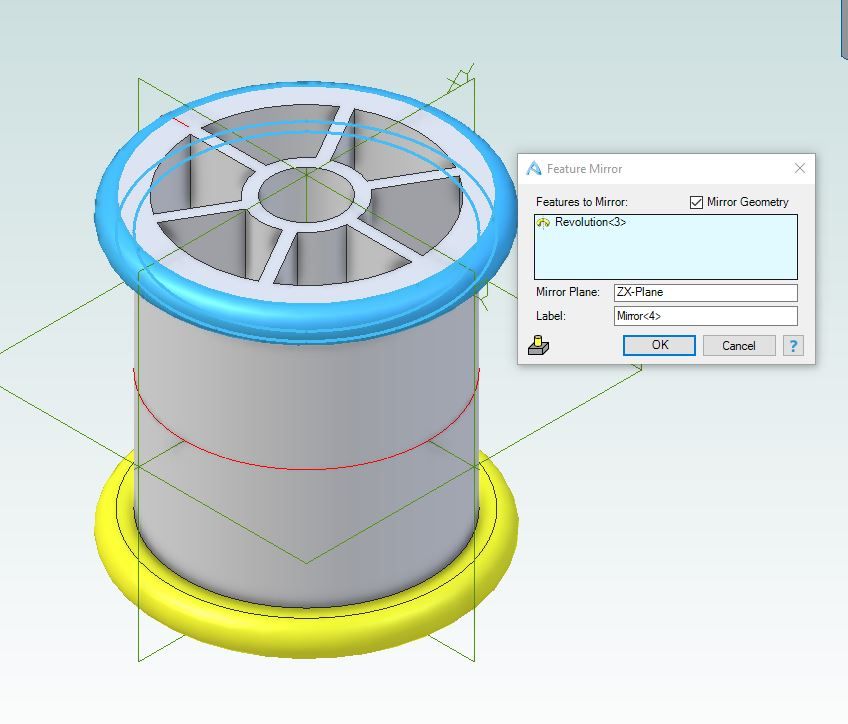
                                      First analyse the part and work out a geometric design sequence in one's head. We can see that the part has symmetry around mid-depth (ends are mirror images) and also has rotational symmetry around the vertical axis. First sketch creates the outer rim and cylinder, and the inner cylinder, which are then revolved around the Y axis:

                                      cotton_reel_1.jpg

                                      I'm using the XZ plane for mirroring. If I was going to 3D print or CNC mill the part i would have taken care to orient the part with respect to the XY plane, as that makes it simpler when importing the part into a slicer or CAM program. Only half of the part is modelled. There's no point in drawing, and dimensioning, both ends. Although not obvious in the above picture the inner cylinder is lower than the outer as per the original part. Add a spoke using the top of the inner cylinder as a reference plane and extrude to the XZ plane. The spoke is constrained to be symmetric about the X-axis and the width is dimensioned. The length of the spoke is unimportant (not dimensioned) as long as it overlaps the inner and outer cylinders:

                                      cotton_reel_2.jpg

                                      Use the circular pattern function on the spoke extrusion to create the remaining spokes:

                                      cotton_reel_3.jpg

                                      Add fillets:

                                      cotton_reel_4.jpg

                                      Mirror everything about the XZ plane:

                                      cotton_reel_5.jpg

                                      Andrew

                                      #594049
                                      IanT
                                      Participant
                                        @iant

                                        Didn't bother taking snapshots as I went along & I also think this can be done in a number of ways. Nor do I really see the point of this exercise quite frankly, because to a large extent – a) the result must depend on the skill of the user (and I'm certainly not the most skilled SE user, so certainly not the best to champion it) and b) I'm pretty sure most CAD systems could do this quite easily.

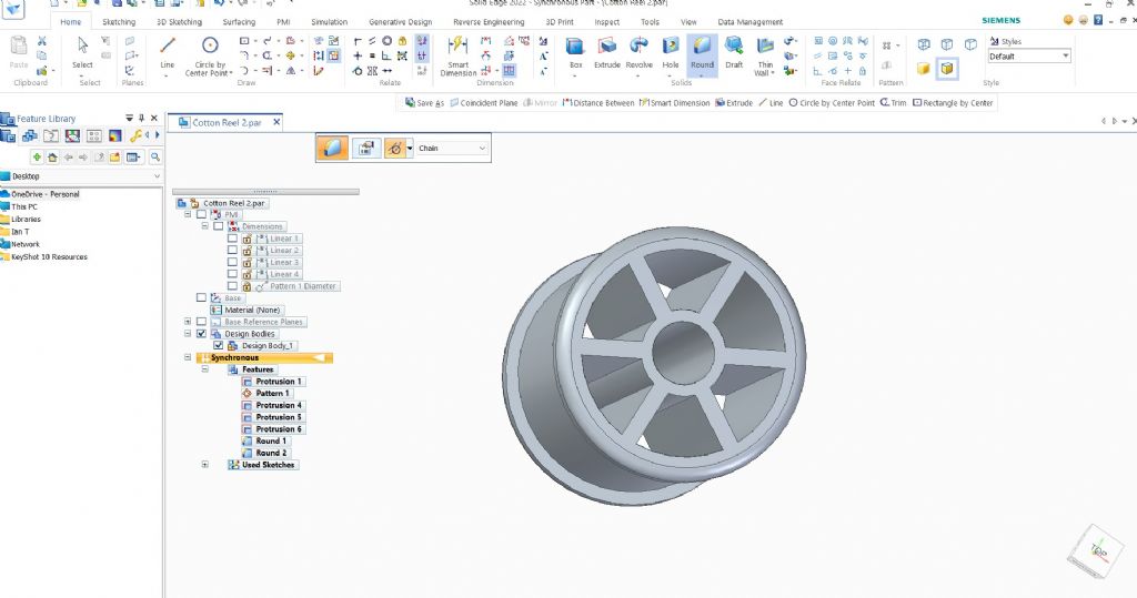
                                        However, in Solid Edge, I did the following;

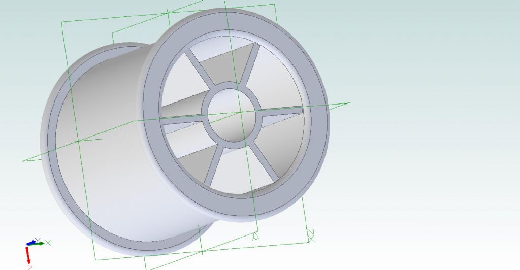
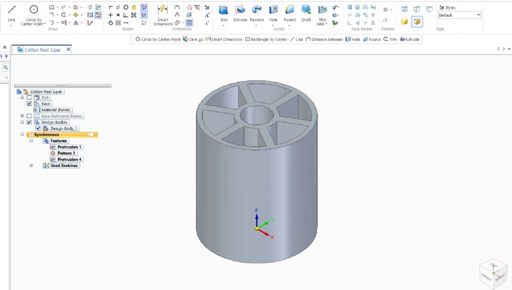
                                        Sketched the basic reel outline (circles by centre) & then dimensioned them, added a spoke (two lines). Extruded the spoke and used circular pattern to create six of them. Extruded circular elements to length. As an after thought added the two outside rims and rounded them. Could have used mirroring but didn't.

                                        Regards,

                                        IanT

                                        cotton reel - 110422.jpg

                                        #594052
                                        IanT
                                        Participant
                                          @iant

                                          PS – When I first started 3D Printing, a friend suggested Open SCAD for my design tool.

                                          It's very easy to get into but does benefit from a more 'programmatic' way of thinking. I'm a bit more 'visual' in nature and also need engineering drawing capability, so moved on to Solid Edge. However, I've written a few simple SCAD models that can be easily modified to suit different applications – and it's very easy to share them too – just a text file.

                                          Adrian's SCAD model was a simple cut n' paste and worked fine in Open SCAD itself – I've no idea about using the FreeCAD version I'm afraid.

                                          Regards,

                                          IanT

                                          Adrians Cotton Reel


                                          Edited By IanT on 11/04/2022 21:44:50

                                          #594062
                                          SillyOldDuffer
                                          Moderator
                                            @sillyoldduffer
                                            Posted by IanT on 11/04/2022 21:27:45:

                                            Didn't bother taking snapshots as I went along & I also think this can be done in a number of ways. Nor do I really see the point of this exercise quite frankly, because to a large extent – a) the result must depend on the skill of the user (and I'm certainly not the most skilled SE user, so certainly not the best to champion it) and b) I'm pretty sure most CAD systems could do this quite easily.

                                            I'd be grateful if you could post snapshots Ian because you''re the Solid Edge ambassador! Without your help we have no idea what Solid Edge looks like, or what steps are needed to get to the answer.

                                            Not a high-skill exercise because a Cotton Reel is pretty simple, and a few interesting ways of doing it have been demonstrated: Adrian's SCAD code is very different from Andrew's mirroring, Nicholas's revolve, and my Pad and Paste.

                                            So far Solid Edge remains a mystery compared with OpenSCAD, Fusion, FreeCAD, MOI and Alibre. And thanks to Blowlamp video I now understand why people like MOI, and must have a play with it.

                                            Go on, convert me to Solid Edge, pretty please with a cherry on top!

                                            Dave

                                            #594068
                                            IanT
                                            Participant
                                              @iant

                                              It's way past my bedtime Dave! frown

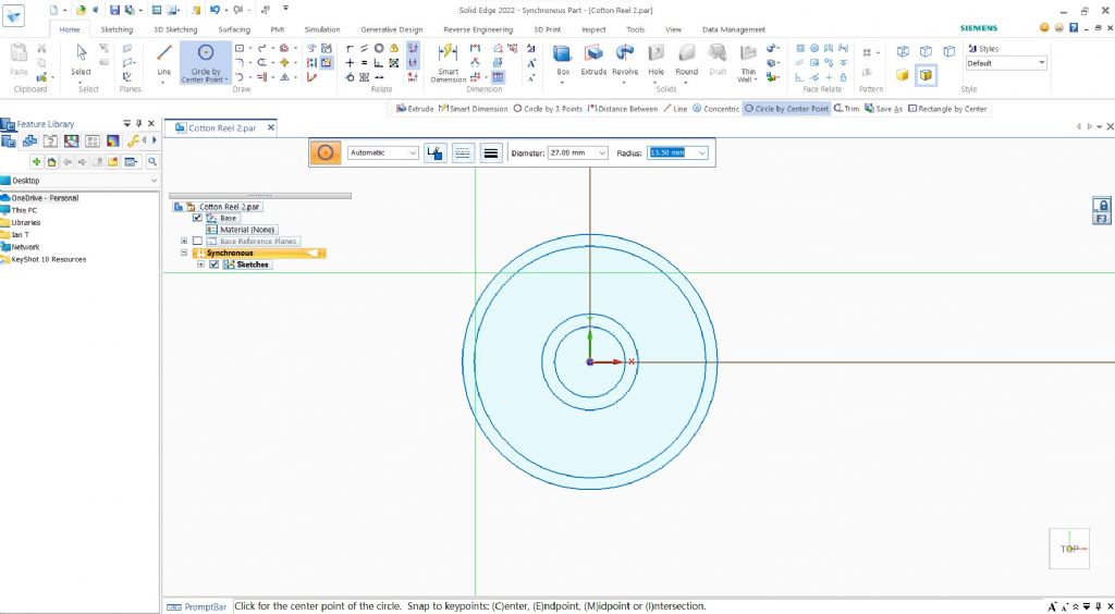
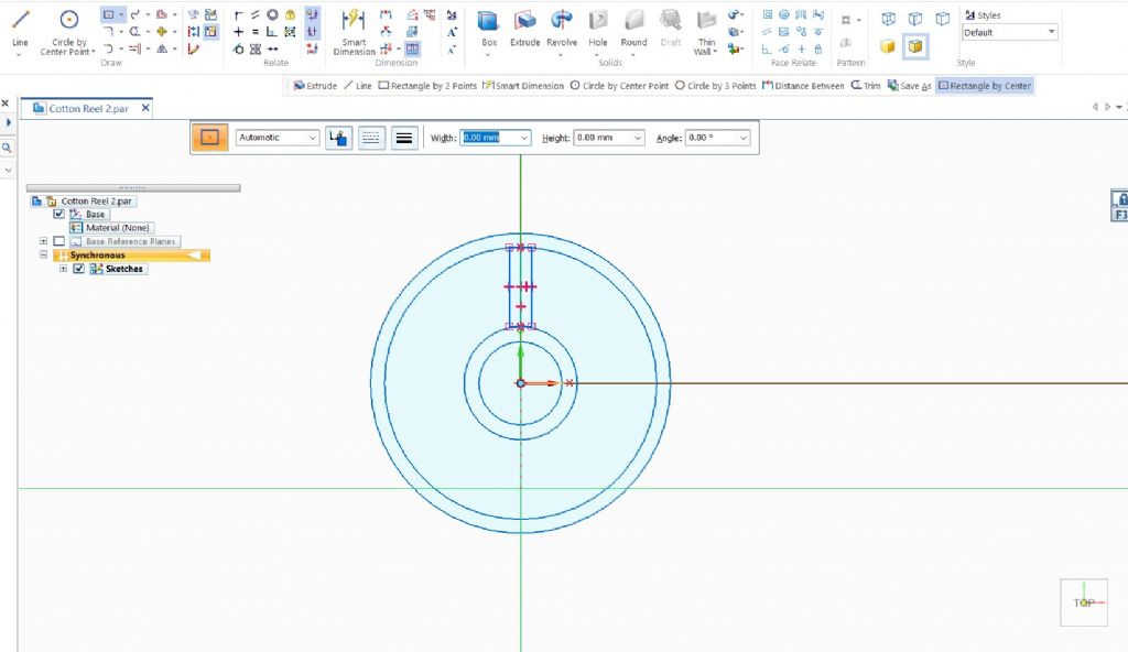
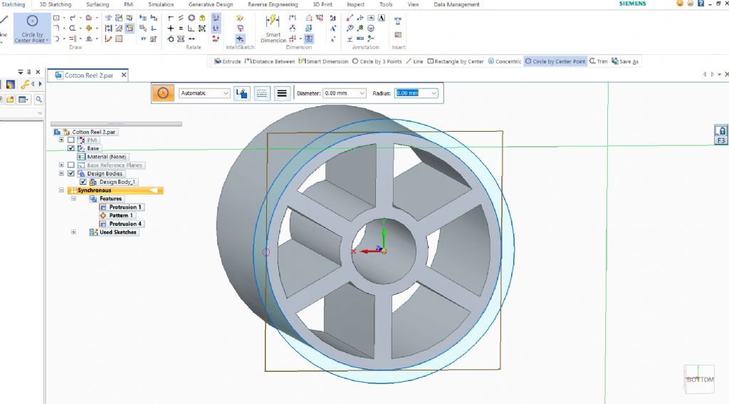
                                              However – here we are. Circles by centre – just click and enter the dims (or size it later)

                                              cotton reel - circles by centre .jpg

                                              Did this a bit differently, drew a reference line and then rectangle by centre, then trimmed. Think it was quicker using lines…

                                              cotton reel - rectangle by centre.jpg

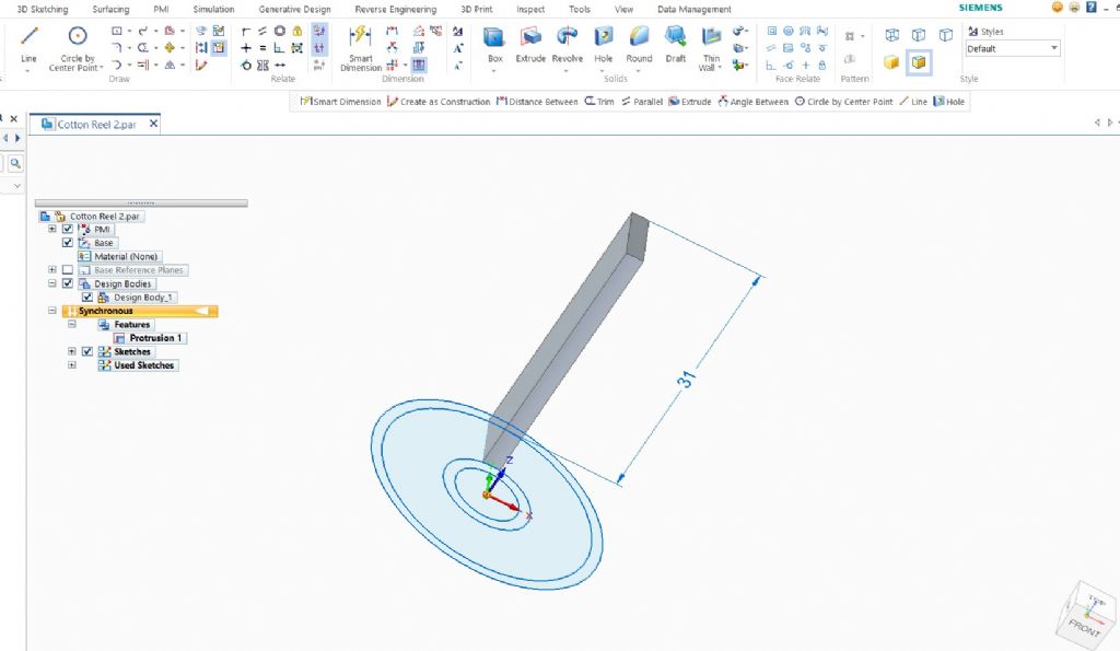
                                              Then extruded the spoke to length…

                                              cotton reel - extrude spoke.jpg

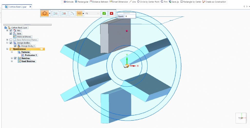
                                              Used Pattern by Circle to make six spokes…

                                              cotton reel - circle by pattern.jpg

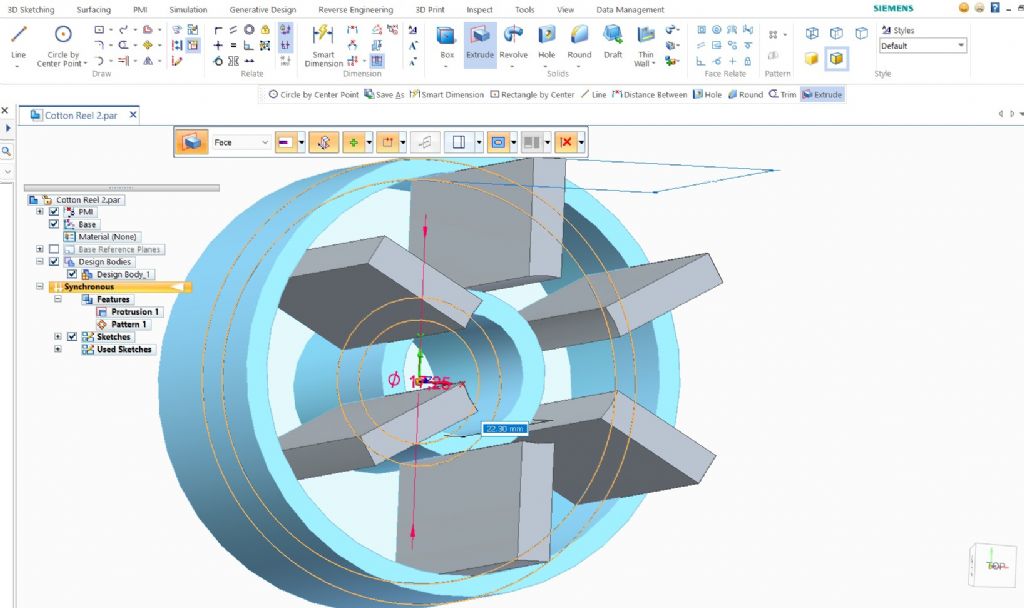
                                              Then extruded cylinders to length (forgot to turn off extrude symmetry for screen grab – but corrected it)

                                              coton reel - extrude cylinders.jpg

                                              Which gave me the basic reel shape

                                              cotton reel - main body.jpg

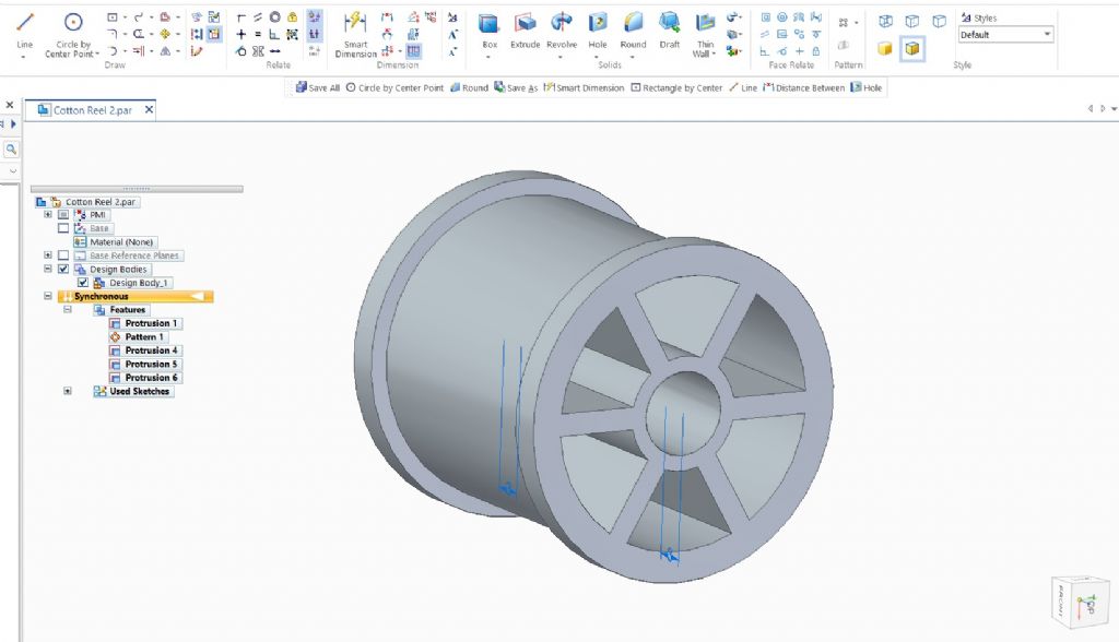
                                              Set my working plane to the end face (note F3 padlock icon) and sketched new rim.

                                              cotton reel - sketch rim.jpg

                                              Extruded this sketch and repeated at both ends. Could have done half model and mirrored – but didn't.

                                              cotton reel - rims added.jpg

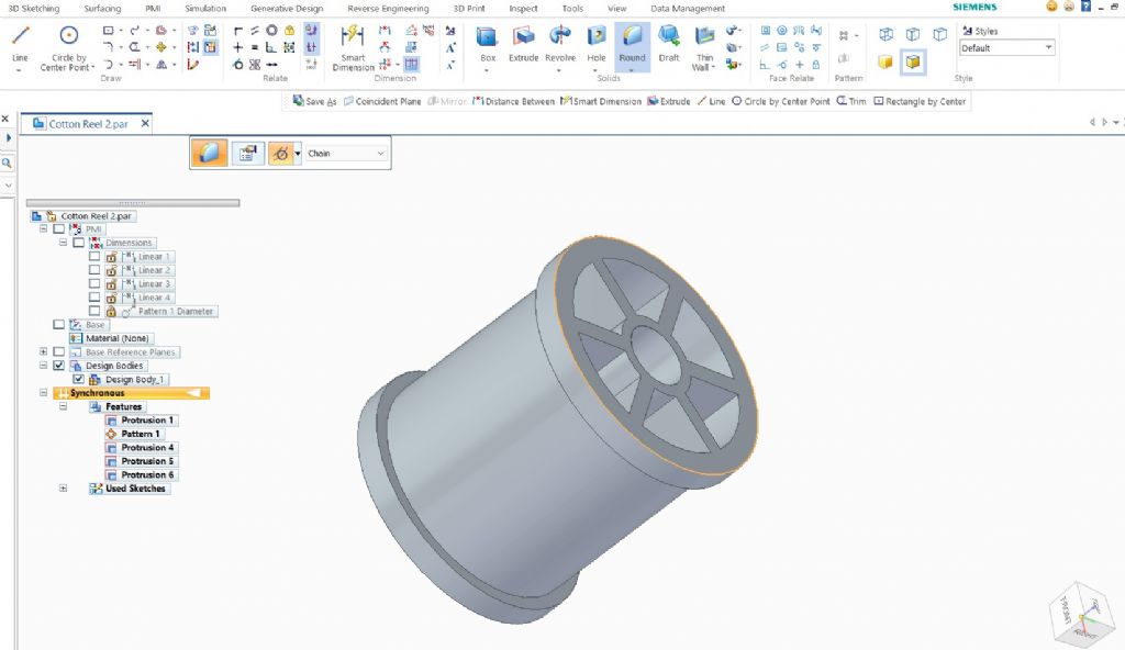
                                              Selected rim edge to round it….

                                              cotton reel - edge rounding selected.jpg

                                              And clicked to round it – same at other end…and that finished it…

                                              cotton reel - complete.jpg

                                              Edited By IanT on 12/04/2022 00:11:55

                                              #594070
                                              PatJ
                                              Participant
                                                @patj87806

                                                I have read a lot about comparisions between various 3D modeling packages, and there are some features that are suppose to make some packages better than others.

                                                In the end, it is not really the features I have found that make or break a 3D package, since these days many 3D packages offer basically identical features/tools.

                                                It is really stability that is important, at least to me anyway.

                                                I looked at Alibre, Autodesk, and Solidworks with I was considering purchasing a package, and ended up going with Solidworks because it had a good reputation, was a very polished package, but more importantly (the most critical thing to me) SW did not have the annual subscription, but instead a perpetual liscense could be purchased one time, with no further fees.

                                                I have seen Alibre do things as well as SW, or better, but at the time, SW seemed to be a more professional package, and I needed it work work, as well as hobby modeling.

                                                I went with SW, and the only gripe I have with it is that the models are version-specific, ie; a model created in SW 2012 is not compatible with any other SW model that was created in a later version of SW, ie: I cannot open a model created in a later version of SW.

                                                I don't exchange many 3D models, and so it is not a huge problem, but I cannot convert files with a conversion program like I can with 2D AutoCAD.

                                                .

                                                #594071
                                                PatJ
                                                Participant
                                                  @patj87806

                                                  There seem to be a large number of approaches to modeling any given 3D part, and my approach has evolved a lot over time.

                                                  In the beginning, my approach was to make models in any way possible.

                                                  I have since discovered that the "editability" (can we make new words here?) of a model varies greatly with how you create it.

                                                  Some models look great, but basicaly self-destruct when you try to modify them.

                                                  I generally draw a sketch in Autocad 2D first, and then import that skeetch into SW.

                                                  I prefer Autocad for 2D work, although SW will also do 2D work.

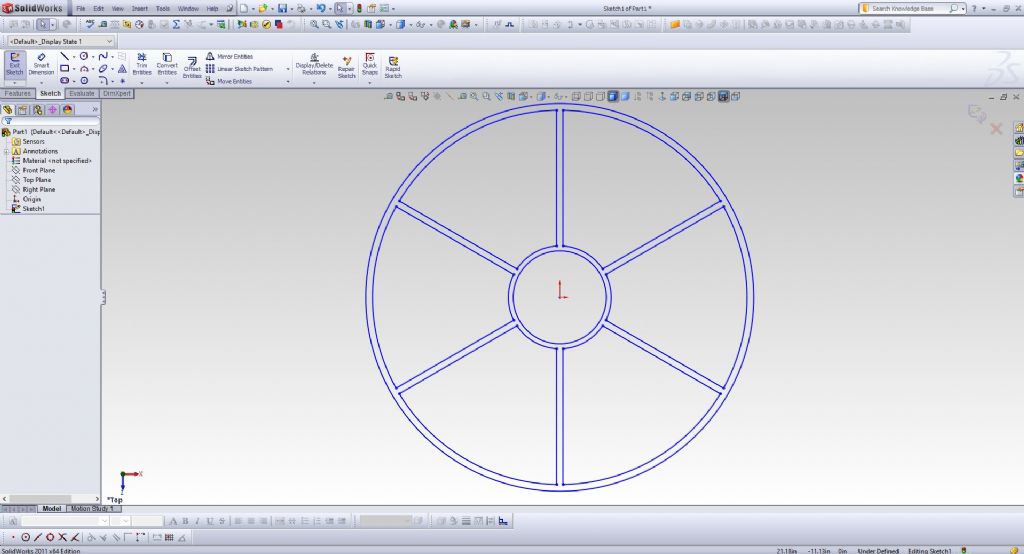
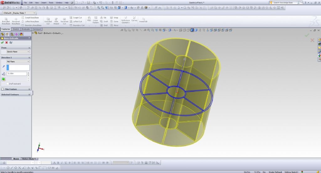
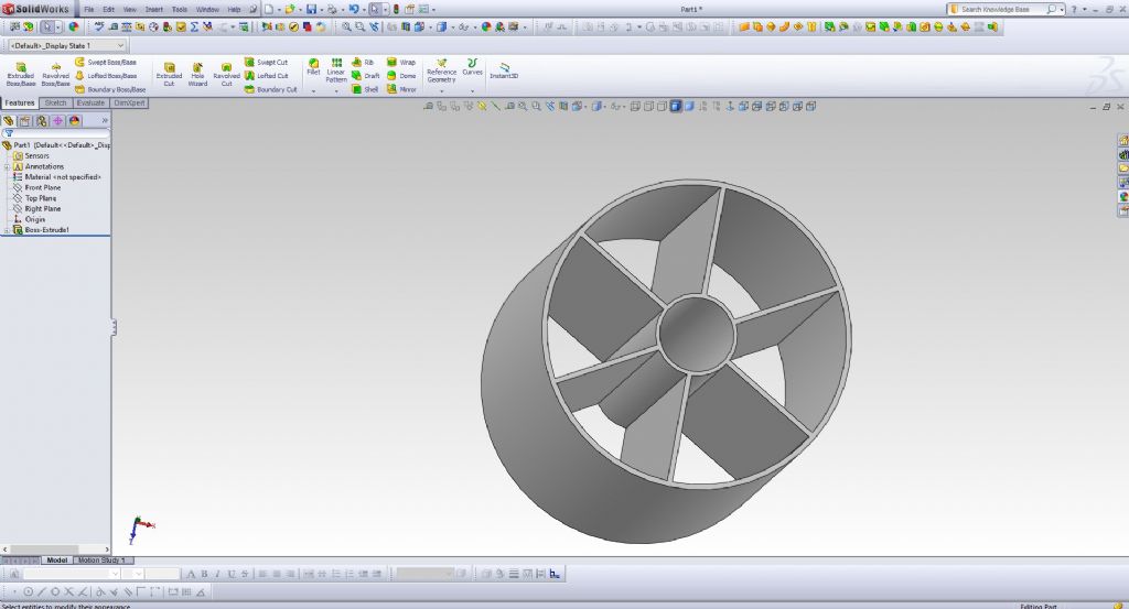
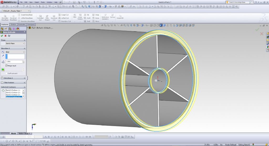
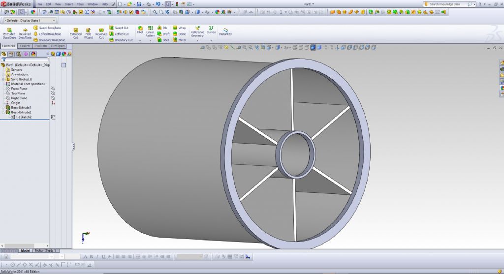
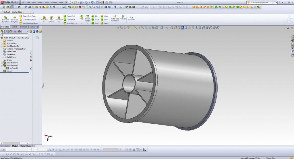
                                                  Here is my approach. Just a few steps to create it.

                                                  As for Solidworks, I find it quite polished and refined, and very stable; definitely not perfect by any measure though.

                                                  ximage11.jpg

                                                  ximage12.jpg

                                                  ximage13.jpg

                                                  ximage14.jpg

                                                  ximage15.jpg

                                                  ximage16.jpg

                                                  #594072
                                                  PatJ
                                                  Participant
                                                    @patj87806

                                                    The fastest way to create a 3D model not necessarily the quickest model type, but rather the model type that can be most easily edited after it is created, especially when you get into complex models.

                                                    Some model shapes are more easily edited (stretched, etc) after they are created, and so sometimes I take a more modular approach, even if it takes a bit more time initially to configure.

                                                    It is a bit of an art, that much is for sure.

                                                    .

                                                    #594080
                                                    JasonB
                                                    Moderator
                                                      @jasonb

                                                      As has been said by others a lot depends on the user rather than the actual CAD package. Interesting that of all the various reels posted Dave's all look the least like the photo he first posted so who if firing blanks? Can't be three programs that can't get the spokes right can it?smile p

                                                    Viewing 25 posts - 1 through 25 (of 113 total)
                                                    • Please log in to reply to this topic. Registering is free and easy using the links on the menu at the top of this page.

                                                    Advert

                                                    Latest Replies

                                                    Viewing 25 topics - 1 through 25 (of 25 total)
                                                    Viewing 25 topics - 1 through 25 (of 25 total)

                                                    View full reply list.

                                                    Advert

                                                    Newsletter Sign-up