Solid Edge Community Edn. – Gen. Qs. Thereof

Advert

Solid Edge Community Edn. – Gen. Qs. Thereof

Home Forums CAD – Technical drawing & design Solid Edge Community Edn. – Gen. Qs. Thereof

Viewing 25 posts - 1 through 25 (of 102 total)
  • Author
    Posts
  • #576318
    Nigel Graham 2
    Participant
      @nigelgraham2

      In the wake of pondering up-dating my PC to WIN-10 (ghastly thought but probably necessary), is my pondering whether to follow that with Solid Edge Community Edition. It seems to have favourable reviews here – but I recognise those are from users far more skilled in CAD than I.

      I would need keep TurboCAD as I would still need my [filename.tcw] drawings I assume not transferable between competing makes of programme – even if they survive the OS change!

      Basically I want some idea if SE would be easier for me to learn than TC is proving. Don't get me wrong. TurboCAD is fine; a very powerful and flexible programme for the experts displaying their superb, very complicated, rendered images on the Users' Forum. Unfortunately it is too difficult for me beyond fairly simple orthographic drawings and even more basic pictorial (3D) efforts of no practical value.

      So to give me some guidance, I'd be grateful for advice on….

      1) Does SE(C) offer the immediate orthographic / isometric choice or is it purely isometric-first or only (as with Alibre and Fusion) ?

      (TC does give that choice – essential if the isometric mode is too difficult!)

      '

      2) If only 3D-first, is it easy to produce the orthographic workshop drawings from the isometric picture?

      (If that is actually possible in TC, I have not discovered how.)

      '

      3) Does its isometric / pictorial method use an equivalent of TC's tangle of work-planes, origins and 'reference points' for assembling an isometric image from its objects?

      (I don't know if all CAD packages use that.)

      '

      4) Is it a straightforward matter to assemble the 3D image from its entities, espcially if those are not symmetrical?

      (TC tools for this are all very difficult to choose and set correctly. Rotating the view often reveals I have made an optical illusion, with the entities apparently joined in one view actually floating somewhere else.)

      '

      5) Does SE(C) use a single, cohesive 3D-object format? I do not mean by which generating tool you select, such as 'Extrude' or a library 'Primitive', but the resulting object's class of internal mathematical characteristics.

      (TC objects seems to be in at least 3 classes, probably according to the selected tool although I have not discovered the pattern. Consequently each reacts in its own, often very strange ways to further editing and manipulating. Sometimes they just disintegrate into irretrievable facets!)

      '

      6) Printing: straightforward or a maze of printer, paper and image setting menus?

      (TC uses a tool called 'Viewports' to copy the 'Model' image to a secondary 'Paper' page; but the whole business invokes several different printer and paper menus – some lacking the ISO-A sheet sizes – with no guarantee of the intended result. Moreover, unless you know exactly how to avoid it happening, making the image fit the paper not only creates a random scaling factor, but also applies it to the values, not just font size, of the dimensions.)

      '

      7) Given some experience in TurboCAD, albeit much less in its isometric mode, might trying SEC be worth it (assuming of course having converted the OS first.)?

      '

      I should say I bought TC in the first place because I knew its advantages over manual draughting and thought it might help me advance my steam-wagon project that's been dragging on for far, far too long. There are no drawings available for it anywhere, just a few old photographs. I'm not sure it's helped me that much – I tend now to make bits to fit and look right, not necessarily to drawings.

      I realised pictorial 'models' are not much use for making things in the workshop, but wanted the option as an 'extra', for producing assembly drawings or the odd non-engineering drawing. For example, I used it once to create some geological diagrams.

      Advert
      #21364
      Nigel Graham 2
      Participant
        @nigelgraham2
        #576330
        David Jupp
        Participant
          @davidjupp51506

          Nigel,

          I can't comment on Solid Edge as I don't use it. Given your difficulty with, and your remaining misconceptions about Alibre (or maybe it's mainly very odd usage of terminology), I'd suggest that for any CAD system you might be interested you'll need to find someone will to show you (in person or by screen share) how to use it.

          There is a lot in common between many of the 3D CAD systems and how they work, though also a few that behave quite differently. I'd judge it just as likely you'll have difficulties with SE, as with the others you've tried.

          If video tutorials and written exercise manuals don't work for you, you may well benefit from something closer to a traditional classroom situation. Being able to have you questions answered as you go along, and those little problems fixed as they happen will make a huge difference.

          Good luck.

          #576332
          JasonB
          Moderator
            @jasonb

            Also before you invest time in learning SE from recent posts here it seems that the "lifetime" free licence is not actually a lifetime but now limited to about 2 years. Who knows if it will still be free after that time period and will you be happy to pay if it is not?

            #576362
            Jim Guthrie
            Participant
              @jimguthrie82658
              Posted by JasonB on 23/12/2021 07:46:19:

              Also before you invest time in learning SE from recent posts here it seems that the "lifetime" free licence is not actually a lifetime but now limited to about 2 years. Who knows if it will still be free after that time period and will you be happy to pay if it is not?

              I've just copied this off their website at :-

              Solid Edge Hobbyists' web page

              "Free software to bring your ideas to life

              The Solid Edge Community Edition is available to the engineering community, including makers and hobbyists practicing their craft for personal satisfaction, not monetary gain. Create 3D models for printing and prototyping. The license never expires."

              I am not a lawyer smiley but that reads as if whatever you download stays yours for life on your computer. It may mean that future upgrades might cost something.

              Jim.

              #576365
              JasonB
              Moderator
                @jasonb

                See IanT's second post in this thread. He seems to post a lot about how good it is (was) Just Like Muzzer used to say how F360 would remain free and now look at that.

                Edited By JasonB on 23/12/2021 10:24:26

                #576379
                IanT
                Participant
                  @iant

                  Hi Graham,

                  As you will know, I've used TC 2D for over 20 years and started migratiing to Solid Edge about two years ago.

                  I'll try to answer some of you questions but must say at the outset, that I think you may be over thinking this matter – something I'm afraid I regularly do myself. I have posted my advice to getting going in SE Community elsewhere, so won't repeat it but I certainly have no regrets in making this move from TC (although you may be using TC Pro, which has more features).

                  Solid Edge is a "hybrid" 3D/2D CAD system, you can use it just as a 2D system or as a full 3D system.

                  Assuming you have created a '3D' part, you can then very simply create drawings in whatever projection you prefer as well as an isometric projection. As SE is fully parametric, changes to the original part will be reflected in any drawings by simply clicking 'update'. It's worth moving to SE just for this.

                  Workplanes are important in sketching a 3D object but once you understand how to create. lock and use a workplane, it is very straighfordward to use. I never got to grips with 'planes' 3D in TC!

                  Once you creatd your 'parts' you then assemble them into an 'assembly' (surprisingly!) Again, the tools for doing this are very srtaightforward – e.g. combinations of axial align, plane align, edge align etc.

                  I can't tell you too much about SE's "internal format" but I'm pretty sure that it's cohesive.

                  Printing is very easy, having both 'paper' and '3D' print options for the current drawing . You can also choose from a very wide range of file types and export them. With regards '3D' print, there is a built-in slicer, so you can directly 3D print an .stl file if you wish.

                  Solid Edge Community is free to download and use. The license on my '2022' Edition was for just over three years. Siemens seem to be releasing annual Community versions in lockstep with the commercial version, so I will upgrade again next year and hopefully extend my license too. Even so I've had two years (2020) use already and still have nearly three years left on SE/CE 2022, so five years free for a very powerful 3D CAd system (and no Cloud) is OK by me.

                  At the end of the day, if you upgrade to Win 10, then try SE. Nothing to lose if you don't like it

                  But to (slightly-off) quote 10cc & Bob Marley – "I don't like SE, I love it!"

                  Regards,

                  IanT

                  #576380
                  Gary Wooding
                  Participant
                    @garywooding25363

                    I've been using TCAD for more than 20 years and got to be pretty efficient with it. My current version is V21.2 ProPlat and I have no intention of upgrading to a later version. TCAD is basically a 2D CAD system with 3D 'bolted on'. It's quite possible to produce excellent 3D models (I've made some myself), but it can be hard work, especially if you need to make changes. TCAD has excellent printing facilities, but no animation.

                    About 5 years ago I attended an introductory session of Solidworks. It was TCAD on steroids and I was really hooked – until I found the price. It was totally out of range. A year or so later I discovered Fusion360 and, because it was free, I started to use it. Its paradigm is totally different to TCAD's and I found the transition very difficult. I didn't have to think about TCAD in order to draw the things, I just did it, but Fusion was a beast of a totally different colour. The documentation was (is) dreadful and I spent a lot of time watching YouTube videos. A few months later and things were different and I could then use Fusion without really thinking about it.

                    Yes, I know your query was about SE(C), but it's paradigm is very similar to that of the other modern 3D CAD systems (Solidworks, Solidedge, Alibre, Catia, etc) which are designed for 3D work – unlike TCAD which was designed for 2D work and had 3D stuff added on. TCAD allows you create 3D objects by extending 2D objects, and offers a few methods of glueing them together to make an assembly, but that's it. Motion is impossible – at least it is in my V21.

                    The modern 3D systems allow you to create 3D parts from 2D sketches, and combine them to make assemblies that can, optionally, display motion. 2D sketches are far more powerful than TCAD's 2D drawing facilities. Dimensions are defined in the sketches and are generally not visible in the 3D parts. Changes to sketches automatically change the dependant 3D parts. All dimensions are parametric and can be interrelated if you want.

                    Fusion uses a facility it calls Joints to assemble the parts; other systems use things called Mates, which are similar but not identical. As far as I'm aware (I'm sure someone will elucidate), Fusion is unique in allowing the parts to reside in the main model or as separate models, or a combination of both. In contrast, the other systems have two types of files – parts, and assemblies. You combine the parts together in an assembly, where the mates are used to join them and define the allowed movement.

                    In order to print a model or part in TCAD you have to create a Viewport by specifying a boundary around the section to be printed, then switching to a mode called Paperspace where the viewport can be inserted and scaled as desired. You can have multiple, separate, paperspaces and populate them at will. Any paperspace can be printed. 3D models can be saved as STLs and printed on a 3D printer.

                    Fusion, and probably the other 3D CAD systems, has a separate 2D printing facility which can create fully dimensioned 2D orthogonal drawings at any scale you like.

                    Both TCAD and Fusion have very powerful 3D rendering facilities.

                    #576475
                    Nigel Graham 2
                    Participant
                      @nigelgraham2

                      Thank you Gentlemen!

                      I tried Fusion and Alibre – the latter by the MEW offer a couple of years or so ago. The impression both give was that they are used by creating a 3D 'model' by default, though you can (I guessed) take off elevations from that. Later of course they started mentiong £££, but I had already paid fully for TurboCAD!

                      I am not likely to draw for CNC or 3D printing work, even by someone else. So file-type matters only if I need transfer files from TC to anything else.

                      On the somewhat mixed messages regarding SE Community's licence life, what will happen after Microsoft do stop supporting WIN-10? If it is. I met a wall of confusion between MS promoting it and various IT journalists denying it! The point though is that Siemens will not release anything for operating-systems MS no longer support.

                      On learning software, I cannot use videos, seeing them as just demonstrations. I have better luck with static (printed or .pdf) material, and TurboCAD came with a separate CD of progressive tuturials in pdf form, created by Paul 'The CAD' Tracy from whom I bought the set.

                      At the time, TC was the only real engineering and architectural CAD make, easily available at a sensible straight-purchase price, to the amateur; and was regularly advertised in our magazines. (Why is it not now?)

                      I am not worried about animations. If I cannot draw a complete machine in 3D statically, I could never animate it.

                      '

                      On specific points –

                      That you can use SE in 2D or 3D mode is reassuring!

                      TurboCAD's 3D's assembly routines probably are similar internally to any CAD programme, but with different tool names and operating methods. My difficulty in TC is in manipulating isometric entities properly on the complicated Workplane and Reference-point system, leading to my having to use laborious co-ordinate calculations that I am supposed to leave the box of sums.

                      This is compounded by TC seeming to use at least 3 different sets of mathematics for solid entities, giving them different reactions to the editing tools.

                      Having chivvied the objects into place, I would guess Joint and Mate have their parallels in TC's Assemble and Add tools. Assemble makes two objects suggle up to each other pixel-on-pixel along the joint plane, but you can still separate then intact. Add fuses them into one and they cannot be reverted.

                      Assemble of course leaves the part free to be adjusted, or copied across the same drawing. I do not know how to copy any part of one drawing to another drawing. It might involve the ambiguous Group / Explode tool pair that are not the reciprocals they seem on the tool-bar. Explode breaks a polyline into lines, but Group is a special version of Add to create a unified entity, and I do not know its real purpose and operation.

                      As far as I know TurboCAD, at least not 19 Pro, does not have a dual-file system equivalent to "Parts" and "Assemblies". Every part of each drawing resides in the single drawing-file, unless that makes hidden, satellite files for Layers, Groups and pre-sets.

                      I know Viewport is to copy part of a "Model" drawing to the "Paperspace", but it has confusingly vague command names. It is very difficult to set the printer, paper and image sizes, and the intended scale. It is very easy to make the image too small, randomly, taking the dimension values with it. The scale menu assumes only 1:1 or smaller scale, allowing reducing an entire GA but not magnifying the small fittings.

                      I wondered if SE might have a much simpler and more direct method, so provided the image at wanted size will fit the paper anyway, it is easy to set the system to give that.

                      ++++

                      Overall, my first priority will be to keep the computer going for as long as possible, because from past experience I cannot trust WIN-10 to accept my existing software, data files, e-posts, web-site links and registrations, etc. If it does, I would then have to think about loading SolidEdge, but it does seem from your collective observations I might not gain anything. I would have to learn a completely new CAD system and completely new OS (WIN 10), but I would need some idea of my chance of success before trying it. Hence trying to compare TurboCAD and Solid Edge.

                      #576481
                      IanT
                      Participant
                        @iant

                        I believe that MS will officially support Win10 until October 25th 2025 Graham – but Win 10 will of course continue to work beyond that.

                        When opening a 'draft' (2D drawing) in Solid Edge, you first choose the paper size and then scale the part/assembly to fit as required. I don't know if you can scale 'up' (never needed to) but you can certainly scale down. 'Drafts' also support layers – so you can create different versions of the same drawing or use them (as in TC) when just drawing in 2D.

                        If you read my previous posts, you will find that I was able to download the very comprehensive SE tutorials as PDFs – they run to some 200+ pages each – more than detailed enough for most folk. They make a very good off-line reference too and I also provided a link to them at the time.

                        Solid Edge is very well documented.

                        That's about it – stick with what you have/know or upgrade to something new/different. Your decision.

                        You know my thoughts on this subject, others have their own opinion – and that's fine too of course. Time for bed.

                        Regards,

                        IanT

                        #576485
                        Anonymous

                          Posted by Gary Wooding on 23/12/2021 11:04:49:

                          TCAD allows you create 3D objects by extending 2D objects, and offers a few methods of glueing them together to make an assembly, but that's it.


                          Gawd … that sounds like one of Autocad's false starts on 3D CAD back in the 80's … and subsequently abandoned. Start with 2D (which they already had) and work up to 3D. (A kludge at best).

                          They discovered, like everyone else, that if you start with 3D, you have 2D. But of course, they had to rewrite Autocad from the ground up – which they bit the bullet and did.

                          Edited By Peter Greene on 24/12/2021 01:58:36

                          #576493
                          JasonB
                          Moderator
                            @jasonb
                            Posted by Nigel Graham 2 on 23/12/2021 23:09:53:

                            I am not worried about animations. If I cannot draw a complete machine in 3D statically, I could never animate it.

                            '

                            As someone designing his own model I would have thought the ability to animate would be quite high on the list of wants from a CAD package.

                            I use it a lot when designing my engines, ideal to check things like the conrod does not hit the trunk guide or crankcase and that the piston leaves an equal space at either end of it's stroke, ditto valve block. Saves a lot of time making parts that don't fit.

                            #576544
                            Gary Wooding
                            Participant
                              @garywooding25363

                              Peter: Your observation is exactly the same as mine.

                              Nigel: Your observations about TCAD's multitude of editing modes is a reflection on it's origin in 2D and the addition of 3D. This is very apparent with the complexity of the workplane and reference-point system. Not to mention the very different properties between layer-0 and all the other layers. It's also very apparent in the very distributed and haphazard customization facilities, where it's obvious that bits of code from various places have been brought together without any real attempt to integrate.

                              You are wrong about viewports in Paperspace, You can set any scaling you like by selecting the viewport and clicking Properties.

                              All CAD systems require climbing a steep learning curve – clearly you are still climbing TCAD's. The modern 3D systems are really no more difficult, but they are different and vastly more powerful. They don't have the workplane concept of TCAD, nor do they have the concept of layers (at least Fusion doesn't). They also have something that TCAD really lacks – a timeline where you can go back in time to make changes that affect recent modelling.

                              I take your point about lack of support for subsequent operating system versions, but have no real answer to it.

                              I can't speak for SE, but Fusion can use any sized paper for drawings and use any scale you like. I'm sure all the other 3D systems are the same.

                              #576548
                              Nigel Graham 2
                              Participant
                                @nigelgraham2

                                Ian –

                                That is reassuring, knowing Siemens does issue proper manuals for SE. I wish IMSO would do the same for TurboCAD – its on-line "Help" is dreadful and it cannot be saved as it is. Surprisingly, as I do not have a pdf converter, I found it possible to copy the Contents page to create via 'Word' and 'Excel' a printed, alphabetical, coherent index that greatly helps searching for a particular item in the whole thing on screen.

                                #

                                Gary, Peter –

                                That may have been true of earlier version of TurboCAD, but certainly the edition I use has far more than that, and is very clearly intended to allow full isometric model-creation.

                                The Users Forum has a lot of architecural and engineering examples. A while ago one was of a fully-fitted kitchen. This was posted by a kitchen designer using TurboCAD both for the construction drawings and photo-like images to help the customer decide. I take it the contract did not include the bowl of fruit…. The 21C version of the beautiful, tinted pictorial elevations that 19C engineers used in contract negotiations.

                                TC is far more than an orthograhic draughting system with 3D features tacked on!

                                You can create solids in TC by Extruding plane figures as you say, perhaps the main technique in any CAD programme. However it also has a library of at least a dozen "Primitives" (cuboid, cylinder, sphere, etc.) and some generators such as Sweep and Revolve.

                                Its Add tool includes a Subtract and a couple of other moves I forget without running the thing. The Copy functions work in 3D as well as 2D, although I do not know how to copy from drawing to drawing. It is not Copy-and-Paste: you have to Copy the item in its place then Snap the copy to its location, or enter its co-ordinates. There are though array-copy tools for multiple repeats, and Mirror.

                                It does lack fillet and chamfer tools, I think, but there are ways round that – such as using Subtract. I believe the more modern and certainly fuller editions of TC include these and functions like Loft.

                                IMSI has also published an up-dated version, probably intended for W10, and again available at one-off cost at a sensible price for we amateur users who don't need massive industrial-scale editions – even if we could afford them.

                                '

                                Jason –

                                Don't get me wrong: I appreciate the value of an animated isometric assembly drawing!

                                I would find it too difficult, since even the static 3D GA would be. My version of your example is a vertical compound engine and drawing a connecting-rod or eccentric assembly in non-rectilinear positions baffles me even orthographically. The weakness is not the programme but me, and I'd probably find it in any CAD system.

                                Therefore I draw it as best I can to reduce the risk of parts interfering or not fitting, and more or less as I make the thing.

                                So to design the engine I created a rather sketchy outline to establish the enclosed engine's size and position in the vehicle (unusually, between the crew seats. with its mid-height at about chassis level), then started to design the works from inside out.

                                I made and assembled the crankshaft, eccentrics, connecting-rods and crossheads, and put them between bench-centres on the milling-machine table, with a substitute piston-rod in a collet, using the quill as "piston" . Thus I can measure the real main-bearing heights above the part-made baseplate, verify the eccentrics' space (remarkably greedy for room, eccentrics), hence design the plate and bearing pedestals from that.

                                For the valve-gear (Stephensons, the specific design adopted from K.N. Harris' re-working of LBSC's Maid of Kent) I will use a similar approach: draw and make parts; partially assemble, assess real locations and clearances and eventually design the case so the whole engine fairly represents outwardly, the conspicuous original shown in archive photos.

                                CAD and a DRO system on the mill has already give me useful options for making the expansion-links, dimensioned by Harris in umtee-twoths of inches. The programme will give me decimal and angle dimensions, hence milling to thous (ish), Cartesian co-ordinates and rotary-table locations.

                                '

                                To sum up, my limit of software learning is far lower than for most people here, so I need try to judge how I can work within it to the same ends, more efficiently. Same task overall, so perhaps a tool easier to operate for that task.

                                Hence trying to assess if SolidEdge Community might be easier than TurboCAD's equivalent for me. They are intrinsically, equally valid, very powerful, trade-level CAD tools for fundamentally the same work, so the question is of my better choice.

                                #576563
                                Nick Wheeler
                                Participant
                                  @nickwheeler

                                  Nigel, your restriction of trying to force 2d limitations on 3d thinking will mean you're going to be disappointed and frustrated any any of the 3d modellers. you keep repeating '3d isometric' as if it's just a pretty picture instead of a complete, albeit virtual, thing.

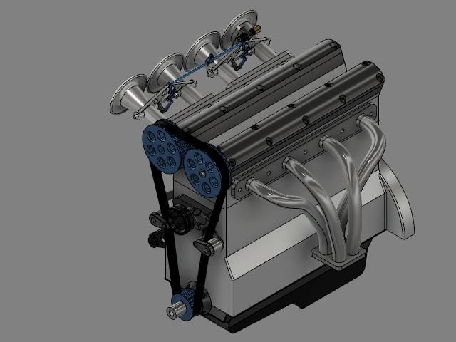
                                  I posted this picture of the 4 cylinder DOHC enginewhole engine.jpg

                                  that I was fiddling with earlier, and that was done in exactly the same way you did your 2d work: by starting with one cam journal, copying and joining it to make the crank, then the block, adding a conrod and piston, adjusting the height of the block to suit, designing the domed combustion chamber and ports, adding the valves, cam buckets and camshafts, then encasing the whole lot in a cylinder head. I did have a few parameters defined, mostly to enable the repeated copying for the multiple parts. Everything was built in place using the geometry that it needs to fit, or avoid. Doing this in 3D meant that tricky things like placing and sizing the round valve seat in a hemispherical chamber could be done by just altering a dimension – I don't want to even see the maths that would be necessary to do that any other way.

                                  I think you need to sit down with someone who can actually show you, in person, using one of your own parts the small tweak you need to your thinking.

                                  #576581
                                  SillyOldDuffer
                                  Moderator
                                    @sillyoldduffer

                                    If I were Nigel, I'd retreat to safer ground!

                                    Designi is difficult. CAD helps considerably by automating parts of the process and allowing the design to be edited to correct mistakes or add new features.

                                    2D-CAD automates old-school drawing board methods, which require considerable effort to learn.

                                    3D-CAD takes a different approach. Many professional Draughtsmen found it difficult to adapt to 3D-CAD when industry abandoned Drawing Boards. An unlucky few found it impossible to adapt to the new mental gymnastics. It's a mind-set thing, much worse than telling someone who has spent their entire career working in Imperial measure that they're going fully Metric tomorrow, or else…

                                    Software is only worth using if it helps. There's always a learning curve, and CAD is tough going. It's important to start with the basics. Huge mistake to buy high-end CAD software and jump straight into developing complex objects. No easy answers or short-cuts : you have to knuckle down and work through it logically, bottom up.

                                    Is CAD worth the effort? Maybe not!

                                    Nigel's mind-set is clearly 'Drawing Board', or 'Orthographic'. I'd build on that rather than fight it. Before 1960, all design was done that way. Dozens of men at drawing boards painstakingly developed drawings that were often physically modelled to identify fit problems. Slow and expensive when scaled-up to design complex objects, but it works. 2D drawings are well suited to basic work.

                                    Although I'm comfy with computers, more than half of what I make is done from simple drawings. Back of an envelope for simple stuff; QCAD 2D for single parts needing more than one projection, or development; FreeCAD or Fusion360 when 3D complexity kicks in.

                                    QCAD has layers, dimensions, snaps, print control, and loads of go-faster ways of drawing lines, circles, rectangles, polygons etc. Took a bit of getting used to, but it's like the Technical Drawing I learned at school on steroids.

                                    I mostly use FreeCAD to develop and visualise single parts. In comparison with QCAD, it's 2D drawing facilities are extremely primitive: it only does the minimum necessary to develop 3D shapes. They aren't substitutes. But what can be done with 3D objects is extraordinary! Once a 3D object is defined, it can be represented on screen or paper in isometric or perspective from any angle. If required, a tool generates First or Third Angle projection drawings: note these are outputs, not how the model is defined. Other tools output the model as a file ready for 3D-printing, routing, engraving, or CNC. Finite Element Analysis can detect weak and over-strong parts. All major advantages, but only if your workshop needs them.

                                    FreeCAD doesn't do Joints or Assemblies in a satisfactory way yet. If they're required – not often – I've been using Fusion360. The effort of learning Fusion was worth it to me.

                                    Although Fusion360 has similarities with FreeCAD, I didn't expect the two packages to work in exactly the same way, or to resemble QCAD. Not everyone would want or need to spend as much time as I have learning software.

                                    So for Nigel I recommend:

                                    1. Abandon 3D-CAD because it's too much work for not much return
                                    2. Adopt straightforward 2D-CAD because it fits the Orthographic mind-set. (I like QCAD because it's similar to the first CAD package I ever used, does what I need, and isn't packed with complicated features. In comparison, AutoCAD is completely over the top for my purposes. Only played with TurboCAD briefly, so unfair to comment, but I found it an awkward mix of 2D and 3D capabilities: not a good fit with my mind-set! Other 2D-CAD programs available.)
                                    3. Having decided on a 2D package stick with it. Put the effort in, whatever warts it has! Worst thing is to switch from package to package hoping to find one that's easy. More likely to confuse than help. Also, don't fight software. Swim with the tide. If a program doesn't work as you expect it to, only you are intelligent enough to change. Stupid software does what it does tirelessly until the human surrenders.

                                    The goal is to get the job done, not to find perfect software. Engineering is all about making compromises.

                                    Dave

                                    #576603
                                    Anonymous
                                      Posted by Nicholas Wheeler 1 on 24/12/2021 12:55:25:

                                      I think you need to sit down with someone who can actually show you, in person, using one of your own parts the small tweak you need to your thinking.

                                      Absolutely. I had the advantage (years ago) of learning 3D CAD in a professional setting. That meant I was sent off on several week-long tutoring courses. I can understand the difficulties that people have with trying to self-learn with no one to sort out their difficulties as they go along. Prior exposure to 2D CAD is probably more of a liability than a help.

                                      What's needed is some form of non-professional "evening classes" at a community college but I guess the demand isn't there – despite what it looks like here.

                                      #576606
                                      IanT
                                      Participant
                                        @iant

                                        Nothing ventured, nothing gained Nigel.

                                        Learning 3D CAD requires some effort and a bit of perseverance – what ever CAD system you eventually decide to use. In my case, I feel that this effort has been rewarded.

                                        It has been a much better use of my time than trying to make something ill-suited to the task fit my needs.

                                        Regards,

                                        IanT

                                        #576617
                                        Nigel Graham 2
                                        Participant
                                          @nigelgraham2

                                          Gary –

                                          I take your point about TurboCAD's origins but without your previous experience, I take TurboCAD 19 Pro as it comes, without worrying about IMSI's software design methods. Though I would have appreciated a much better "Help" section!

                                          It is fairly clear that TC reserves Layer 0 for itself, I think for construction-lines. It took me a long time to work out what Layers are and how to use them though. Unless I misunderstand him, D.A.G. Brown's generic guide to CAD says Layers can be used as an assembly-copy tool, giving tender axle-boxes as his example. I don't know if or how that works in TC though.

                                          Thank you for the Viewport properties tip. TC allows any standard paper sizes, logically enough. Except it makes copying, scaling and printing a drawing from its original Model Space life about as hard as possible; muddled by several different paper-size lists of which some give only American ones.

                                          Often I find its easier to copy and paste the drawing and to Hell with Viewport – but it still risks altered dimensions, and raising Hewlett-Packard's common, mystifying printer error-message about printing boundaries or something.

                                          '

                                          Certainly right about climbing a steep learning-curve; though I recall reading that a +ve-going parabolic arc in any learning means little progress at first then accelerating advancement! Not harder and slower but easier and quicker learning; having grasped the principles. dl / dt and all that. My curve follows no known mathematical law and often dips, reaching only foothills to inaccessible summits. Besides, as a poor climber with an unreliable head for heights (as would aver any of my caving friends of over 40 years)…. as in reality so in metaphor.

                                          '''''

                                          Nicholas –

                                          Thank you.

                                          I am not trying to force 2D restrictions on 3D. I know they are very different, and that a 3D design model is not merely pictorial. It forces restrictions on me, stopping me from doing what it lets its expert users do: design complex assemblies by 3D "models" that then become the source of the parts drawings.

                                          I recognised the isometric modelling that CAD can give before opting to buy it. As well as all the other advantages, I wanted to be able to create isometric views of parts and complete assemblies. At the time I did not know if you can take off elevations for workshop use. I now know you can, but not how.

                                          You refer to "parameters" for copying repeated parts – referring to a method specific to the CAD programme you use? The word is not in TurboCAD, but TC probably has equivalents much more efficient than the way I operate it.

                                          I know what an expert CAD user can do, but I need be realistic about what I can learn. Your engine is perfectly possible in TurboCAD, but reaching that skill level is not possible in me.

                                          So I am asking advice to help me judge if I might use CAD to better advantage by using a different make, easier to learn.

                                          In any case, I cannot use SE unless and until I install Win-10; but I do not know what problems that will create.

                                          +++

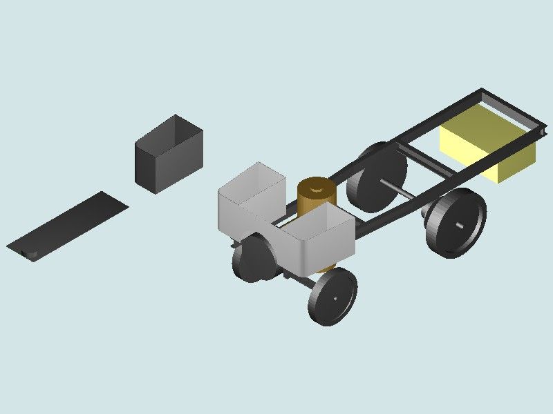
                                          The drawing below is probably the last isometric CAD attempt I have made so far, and many months ago.

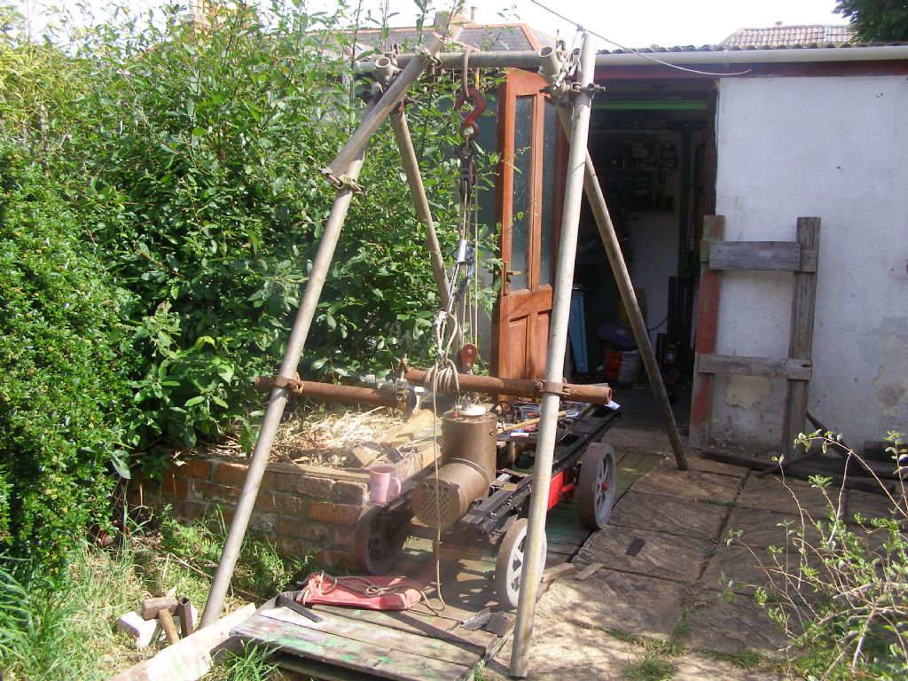
                                          It is a general view of the 4" scale steam-wagon I have been taking far too long to make. There are no drawings for it, just a few old advertising photographs from 1908. This drawing reached my CAD skill limit, but despite parts removed, the construction stage is roughly that of the photo below it.

                                          I took that when trying to design the boiler-mountings I made eventually to a rough pencil sketch and bits of steel clamped to the chassis. The red bit in the photo is tentatively the outer plate for the transmission assembly.

                                          The drawing's two floating bits are a bunker and its floor, extended as the footplate. I took many attempts to draw that sub-assembly as neither a solid block (nowhere for the coal) nor lacking a floor (chassis rail visible in plan, the coal landing on the ground).

                                          The brown cylinder is the firebox, the boiler shell being a T-piece standing on its side. The wheel discs are not really solid but pairs of rose-pierced plates. The yellow block represents the water-tank (brass). The rear axle is correct by dimension but looks too far forwards. The disc behind the wheel is the differential, converted from a car unit to traction-engine pattern with through and cannon shafts, and fitted with chain sprocket

                                          I could have added the seats (two rectangular boxes) and symbolised the engine (another box, between the seats and behind the boiler). Detailing the wheels, adding the Ackermann steering-gear, springs etc – out of the question. All that lot is nearly as far as the vehicle itself has progressed.

                                          This drawing conveys far less than a photograph of the made parts. As a TurboCAD 3D model – merely an exercise; scrappy, unfinished, best deleted. As a design drawing – dimensionally right but useless. Its only value is as a self-assessment of ability.

                                          Experimenting though, I was surprised to find that TurboCAD will dimension a scanned photograph – but 2D only so useable only on planes perpendicular to the view. Nevertheless I used this to obtain some approximate dimensions for the engine-case.

                                          vehicle ga 3d attempt.jpg

                                          HLDV boiler fitting 07-06-20 a.jpg

                                          #576631
                                          David Jupp
                                          Participant
                                            @davidjupp51506

                                            There is no such thing as 'isometric modelling', nor 'isometric CAD'.

                                            Isometric refers to a particular family of view/projection orientations. Like any other projections, these can easily be derived from the 3D model, in most modern 3D CAD systems.

                                            #576670
                                            Nigel Graham 2
                                            Participant
                                              @nigelgraham2

                                              So, how is the default 3D angled projection described on the package you use?

                                              I was sure TurboCAD does call it Isometric.

                                              So I have just opened a TC 3D drawing to see. Yes, the three oblique-view options are all called "Isometric_ xxx " where " xxx " is the view's compass-bearing.

                                              I recall from my brief brushes with them, Fusion and Alibre defaulting to similar obliquity so assumed these too would use the label "isometric", or just not label the different view angles at all.

                                              Sometimes my 3D drawings took on Escher-like characteristics when revolved, so I would tack a tiny sphere to the default nearest, lowest corner as an orientation guide.

                                              '

                                              Going back up-thread a bit…

                                              Dave –

                                              I should have said a while back I can use TurboCAD's 2D mode well enough for my own use, blissfully ignoring fancy font standards, formal title blocks and such. (My titles are just simple text-boxes; big letters, nothing special or consistent.)

                                              You highlight the problems of moving to 3D when you've only ever been used to drawing orthographically. I think that's more for professional than amateur draughtspeople, due to the far greater exposure to it. I used 2D drawings professionally but never made them.

                                              Manual drawing calls for considerable skill at times, such as in designing cams or interpenetration-developments, but I'm not sure it was necessarily harder than learning CAD. The skill was different but at possibly similar level. Also the manual methods were all so well-established that a few easily-obtainable reference-books would help you, when occasionally encountering something unfamiliar. I have such books and even if >50 years old, what they show is intrinsically unchanging. Unlike obscure commands in a manual for one, relatively short-lived, computer programme.

                                              So the skill has moved from understanding the plotting to understanding operating the plotting software.

                                              ===

                                              Indeed, can I use TurboCAD for just such a purpose, on my project ?

                                              My wagon's boiler is a T of 2 cylinders of different diameters; and made (by Western Steam): photo above. I need though, lag it. So how to develop the cladding sheets? Four options:

                                              1) By CAD. Drawing the boiler shell and cladding, as assembled cylinders, is simple enough for me even in 3D; but does not give the developments.

                                              2) 'Excel' to calculate edge co-ordinates along the unrolled sheets. Making the speadsheet is easy; but deriving the many formulae?

                                              3) Manual development, on paper, having revised from one of my old text-books the method I learnt – well, was taught – at school half a century ago. Make a card test copy of the graph, to go over the fitted crinolines, which may be wooden rings, before cutting any metal.

                                              4) This occurred to me today while out scran-foraging! Mark the crinolines' edges at regular intervals. Fit them, aligned mutually and with the shell. Measure from each division to the rule's contact on the associated crinoline (mm easier than inches here). Transfer the measurements to the card test-sheet, join the dots.

                                              SO

                                              Method 1) – Clearly out: gives a neat drawing but not the answers.

                                              2) Accurate answers if it were possible. Which it is not.

                                              3) and 4) Feasible, 3) perhaps simpler and quicker.

                                              '

                                              I still don't know if SE would be easier to learn than TurboCAD, to a more useful level. Occasionally I still try TurboCAD's 3D option I must not call Isometric whatever IMSI says; but do not believe I could ever reach the sort of level Nicholas shows above, with his car engine.

                                              Incidentally I think we may have misunderstood how we each work. Nicholas seems to describe making the entire drawing part by part, from part drawings; before shaping any metal. I make some components from simple 2D drawings, then bolt them – the bits of metal – together so I can draw the next bit. I have not drawn anything in entirety, beyond some scrappy 2D sketches. Sometimes I have to scrap parts made perhaps several years ago but now causing unforeseeable problems: frustrating but that's how it goes. I thought using CAD – having seen its possibilities at work – might help me reduce such problems. Clearly not.

                                              #576675
                                              JasonB
                                              Moderator
                                                @jasonb
                                                Posted by Nigel Graham 2 on 25/12/2021 01:21:03:


                                                1) By CAD. Drawing the boiler shell and cladding, as assembled cylinders, is simple enough for me even in 3D; but does not give the developments.

                                                Method 1) – Clearly out: gives a neat drawing but not the answers.

                                                Even this comes down to the users ability to make good use of their chosen CAD package. Although Alibre has the ability to do sheet metal work just like several other CAD packages including TurboCAD I don't pay for that version but I have been able to develop the true shape of curved parts "on the screen" and produce firstly a 3D model of that flat part and from that a DXF file (2D drawing) for laser cutting. Yes it is a bit more long winded than the sheet metal option which just flattens the part and includes all bending allowances, etc but it works.


                                                Edited By JasonB on 25/12/2021 07:45:06

                                                #576704
                                                Gary Wooding
                                                Participant
                                                  @garywooding25363

                                                  Nigel: About TCAD. My V21.2 came with a 475 page Reference Manual in the form of a PDF. As a reference manual it's pretty good, but it's not a tutorial. If you don't have it, drop me a PM and I'll send you a copy. I painstakingly divided it into 4-page signatures which I printed in booklet form on A4 sheets and then folded each page and bound them together to produce a 475 page A5 book. I found it very useful.

                                                  When in Paperspace click File and then Page setup to choose whatever page size you want. You can specify your own page size with the Page Setup wizard. You can even define a very large print area and 'tile' it with sheets of your choosing. TCAD will handle it for you.

                                                  In Modelspace, click Modify and you can choose Fillet or Chamfer.

                                                  TCAD has all the tools you need to produce really good 2D drawings or fully rendered 3D models – I know because I've done it. But, compared to a modern 3D CAD system, the tools are blunt and somewhat sparse.

                                                  All good CAD programs are complex and require a steep learning curve. It seems to me that you have really just started with TCAD and still have a way to go. It took me at least a year to become efficient enough to use it without really thinking about it. After a day's worth of Solidworks I was convinced that a true 3D system was the way to go, but I had to wait until Fusion came along. Had I known about SE(C), or equivalent, then I guess I'd be using that now.

                                                  I take the point about the Win10 requirement, but to my mind that's really not a good reason to spend time and effort on learning an outdated system. Far better to bite the bullet and go for something more up-to-date.

                                                  Both TCAD and Fusion came with many tutorials, none of which I found useful. I'd probably feel the same about SE(C). My main source of learning was with queries on the relevant user forum and Youtube videos from presenters sifted from many that were a waste of time.

                                                  It seems to me that, after painstakingly learning to use pen and ink you're getting to grips with a typewriter, where you should be starting to learn a word processor.

                                                  #576780
                                                  Nigel Graham 2
                                                  Participant
                                                    @nigelgraham2

                                                    Thank you very much, Gary, for your very generous offer; but as you dojn't have a public profile, it tells me, I cannot see how to send you a PM!

                                                    '

                                                    My typing's ropey too – and I've done plenty over the years, including editing two caving-club magazines and writing a book mss – the last using an Amstrad PCW9512 with daisy-wheel printer.

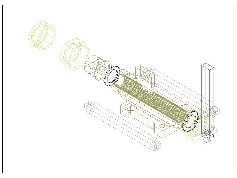
                                                    Anyway this peculiar drawing's intact original is a step towards the sort of assembly-drawings and exploded-views I was hoping to be able to draw, BUT…..

                                                    …. Why on Earth has copying it thrown the rendering away – neither intended, nor previously met?

                                                    hand-pump sectioned  jpg.jpg

                                                    This drawing is still rendered in Model Space, but the Viewport and/or Paperspace reverts it to wire-form, with correction not allowed in Paperspace. This while still within the .tcw file so not an effect of saving a copy as .jpg image for importing here. It all worked properly with my wagon drawing.

                                                    This has never happened before. So not content with its baffling Viewport and Paperspace system, TurboCAD is now spoiling the presentation!

                                                    '

                                                    A note on the pump's design: The bronze casting is about 4.5" long x 1" dia. to be bored or reamed between-centres right through. The hexagons holding the tail seal and valve-block are standard plumbing union-nuts, the far one showing an optional modification to 12-sided for appearance. The male threads on the barrel ends are indicated in that spider's-web simply by crest-diameter spigots. I would use conventional thread symbols and text note on the working drawings I still do not know if can be produced from the 3D model.

                                                    ++++

                                                    I take your pen etc. analogue. It took me long enough to learn to use a word-processor to an appropriate level, far below what the programme can offer but everything I need. I have gained help several times from the TurboCAD Users' Forum.

                                                    Thank you for your kind offer. I know the editions of TC vary in what tools they offer, and I use 19 Pro, but there should be enough that is the same.

                                                    Someone else sent me a tutorial exercise a couple of years ago, of a bracket made from thick plate; but although I could translate differences in tool names and screen-shots, it needed the Bend tool not in 19 Pro. I omit Fillets and Chamfers, instead taking them as read, or adding a text note.

                                                    If I convert the PC to WIN-10 (or buy a new one able eventually to take 'WIN-11-v.bloat' ), I think from this thread that my choice will be SolidEdge Community or the new TurboCAD, which I guess is written for W10.

                                                    Edited By Nigel Graham 2 on 25/12/2021 22:35:00

                                                    #576794
                                                    Anonymous
                                                      Posted by Nigel Graham 2 on 25/12/2021 22:28:30:

                                                      Thank you very much, Gary, for your very generous offer; but as you dojn't have a public profile, it tells me, I cannot see how to send you a PM!

                                                      At the bottom of his (or anyone's) post is "Message Member".

                                                    Viewing 25 posts - 1 through 25 (of 102 total)
                                                    • Please log in to reply to this topic. Registering is free and easy using the links on the menu at the top of this page.

                                                    Advert

                                                    Latest Replies

                                                    Viewing 25 topics - 1 through 25 (of 25 total)
                                                    Viewing 25 topics - 1 through 25 (of 25 total)

                                                    View full reply list.

                                                    Advert

                                                    Newsletter Sign-up