origin of CAD

Advert

origin of CAD

Viewing 17 posts - 1 through 17 (of 17 total)
  • Author
    Posts
  • #562098
    brian jones 11
    Participant
      @brianjones11

      Does anyone know what we all take for granted in CAD

      ie drawing of a line (vector between two points (vertices) on screen

      Yes it started with some guy in 1950 with his sketchpad app

      Two points in 2D plane yes got it

      Then there;s a clever little algorithm that draws a line between the two points taking into account your screen resolution. Note that line does not pixilate no matter how much you zoom in

      If you ascribe dimensions to your line say

      then draw 3 or more lines to make a shape

      you can scale up or down x millions (within 13bit range of FP calcs)

      That line stays solid on screen

      That I believe was the dawn of CAD

      Your 2D sketch became a chart of xy vector data as per DXF format

      Note that the sketch could be tied to a point origin 0,0

      I think this is how Acad got started.

      Ive tried googling this point with all bluff and glossing over.

      Where is this going

      Well I want to show how we made and important transition to 3D (not the half baked attempt by Acad to tie 2d views to make a 3D wire frame

      I think its all to do with extruding from a sketch face but one step at a time

      Trying to see how it came about is even more nebulous smoke and mirrors

      example from siemens

      https://www.plm.automation.siemens.com/es_es/Images/WP_2D_to_3D_DesignEngineer_tcm52-21760.pdf

      the most egregious management – speak claptrap

      dont waste your time

      Why is this visceral inspection needed? You just load up the app?

      Well it helps to understand what you are really doing with your models and why they are likely to go wrong

      Because there's the difference 2D drafting was simple both in concept and geometry

      3D opens up a potential can of worms as you are sketching in 2D – your pc screen – and this is translated by the app into a 3D space model. That is a BIG jump

      Which ever 3D app you choose they all have to follow the same route and an important concept of Historic vs Synchronous listing

      Advert
      #21354
      brian jones 11
      Participant
        @brianjones11
        #562144
        Ady1
        Participant
          @ady1

          I would think they are just fixed points in a 3d space

          They are put into different hierarchical groups with different properties

          The interesting bit is when they interact and the REALLY interesting bit is when you change a subset group within this hierarchy and it has to change many hierarchies

          When you program in a computer language and you do it a lot it influences your brain just like any spoken language would

          I figured out how to program chess in basic but stopped computer programming at the same time because it was affecting me in the real world, It is not a coincidence that the majority of programmers who disappear down the computer programming rabbit hole are male

          #562166
          SillyOldDuffer
          Moderator
            @sillyoldduffer
            Posted by brian jones 11 on 09/09/2021 19:35:33:…

            Well I want to show how we made and important transition to 3D …

            I think its all to do with extruding from a sketch face but one step at a time

            Trying to see how it came about is even more nebulous smoke and mirrors

            example from siemens

            ….

            Why is this visceral inspection needed? You just load up the app?

            Well it helps to understand what you are really doing with your models and why they are likely to go wrong

            Because there's the difference 2D drafting was simple both in concept and geometry

            3D opens up a potential can of worms as you are sketching in 2D – your pc screen – and this is translated by the app into a 3D space model. That is a BIG jump

            Tricky stuff this! My engineering mind likes to start with basics and build on them. The method works quite well up to a point: an IC engine can be maintained by understanding 'suck, squeeze, bang, blow', but much deeper knowledge is needed to design a high-efficiency engine that meets emission requirements. Fortunately it's possible to drive cars without understanding any technical details: provided it works, the technology doesn't matter. The driver learns the controls and the rules of the road, and can ignore Carnot and the scientific relationship between energy, work and power!

            CAD is the pinnacle of three millennia of human endeavour. Depends entirely on mathematics as applied by software engineers to run on leading-edge computer hardware. Impossible for an individual to understand all of it. Doesn't help that many CAD packages come with multiple 'workbenches' and it's not obvious which should be used. On first sight they seem packed with unnecessary functionality, causing beginners to bail out in favour of a basic package. The shortcomings of basic CAD hurt much later, when the user discovers he's outgrown the software: this can be agonising.

            I do have a simple mental model, it is:

            1. The design projects 3D from 2D sketches and sketches can be drawn on faces and planes.
            2. Projections include removals, making holes, as well as extrusions
            3. The end result is the sum of many previous steps, and changing early steps ripple through the whole model. It's possible to break a model by entering impossible dimensions.

            Existing mental models can be a serious obstacle to learning 3D. 2D drawing (wot I learned at school), translates 3D objects into plan views. It's the exact opposite of how 3D modelling, which creates solid objects from 2D. A serious error is to assume the Sketch editor produces old-skool technical drawings, which it sort of can. However, it's dangerously misleading and a learning dead-end. The process is:

            • A series of Sketches define a single 3D object
            • 2D Technical Drawings are generated by the software from the 3D object, not by the draughtsman.

            Common for beginners with 2D experience to come unstuck because the sketch editor is a poor 2D CAD tool: if you think that's a problem, you're doing 3D wrong. Can be very difficult to unlearn 2D, or to move from one 3D package to another. You have to learn how the package works rather than trying to bend software to work as you imagine it should!

            The easiest way to get started is to have someone else show you. Otherwise keep an open mind and don't expect grown-up CAD to be simples! Design is the hardest part of engineering.

            Dave

            #562178
            IanT
            Participant
              @iant

              I'm not sure I'm following everything is this thread but I would agree that moving from 2D to 3D requires some rethinking of the way you approach things.

              As a simple example, in 2D you draw a line of a certain length (perhaps at an angle) and then draw more lines, defining the length of each as you go – making sure they are all connected of course (e.g. good 'snaps' ). So a square would be drawn by drawing a line of certain length, drawing another line (the same length) at 90 degrees and so on until you've drawn four lines of equal length.

              When I started 'sketching' in 3D it was easy to do use exactly the same approach but it is far better to think in terms of relationships instead of absolutes.

              So for instance, to draw a square I'd now draw a line (any length), then another (any length) and so on twice more, just making sure the area was closed (e.g. all ends are connected) – but not dimensioning. You might end up with an odd looking four sided object – but provided it closes then all is fine. It's very quick to do too – five clicks.

              Then you add 'constraints' that define all lines as being 'equal' and the two opposite set of lines as being 'parallel'.

              You have now drawn a square but of no defined size. So finally, dimension just one edge and (because they are constrained to be so) all the dimensions will change to match! Need a cube? Well extrude the square and constrain the depth to equal the width. I guess you could say Design then Dimension.

              This is a very simple concept (and I'm sure experienced 3D CAD users will think very basic) but it took me (a 3D CAD amateur) a while to realise this was a better (& simpler way) to work in 3D.

              BTW – for anyone thinking of trying 3D CAD – don't be put off by the fact that you need to spend a little time learning it. Most worthwhile things do need some effort to become proficient. I used 2D CAD for many years but I am a real 3D CAD convert now. I've still a long way to go but the sooner you start out, the sooner you'll get there.

              Regards,

              IanT

              Edited By IanT on 10/09/2021 10:59:37

              #562184
              brian jones 11
              Participant
                @brianjones11

                q

                I'm not sure I'm following everything is this thread but I would agree that moving from 2D to 3D requires some rethinking of the way you approach things.

                uq

                you might say "ive been driving a car all my life, now I want to learn to fly"

                if you listed the difference between a car and a plane, it might total up to how different 3D is to 2D

                Note

                you dont need to know how to drive a car to fly a plane but it sure helps you to get to the airport if you can drive

                thats what you are facing as a nooblaugh

                #562194
                Another JohnS
                Participant
                  @anotherjohns

                  I'm with SOD – vector math has been around for millennia. Quaternions for at least 150 years. Bresingham's line to pixel algorithm came out when I was still in diapers.

                  Maybe I'm biased, though. We see history through our own experience and yours might be *very* different than mine. I spent quite a bit of time on writing code for 3D graphics rendering when working, and I see CAD UIs as just one way of generating 3D data for rendering. (the graphics code I wrote/managed is/was open source; for a bit was distributed by Apple in the days before the App Store, downloaded millions of times; some funding came from the US DOD, and likely still is the most used and longest running open source project managed by the Canadian Federal Government)

                  #562200
                  Nigel Graham 2
                  Participant
                    @nigelgraham2

                    Interesting history and thoughts.

                    Dave –

                    I would take issue with one point you make. It may reflect what you and I were taught at school (or anywhere else) but the A-Level course I took did include two 3D representations.

                    Bearing in mind that whether T-square and paper or computer screen the image is physically 2D anyway, these were:

                    – Isometric projection (CAD packages seem to call it just "3D&quot. Awkward and long-winded manually, but ideal for assembly-drawings and the like.
                    – "Lines in Space" – relationships between oblique lines that cross with or without touching, in three dimensions; and typically, determining the shortest line linking them. Our teacher warned us that if you don't grasp the principle at the start, you will find it very difficult. He was right there!

                    Coming to CAD from years of being accustomed to making and using only orthographic drawings, it is not easy to think in the isometric "model" first approach; and it can place a massive barrier to producing the orthographic drawings you need actually to make the item. (Assuming non-CAM methods.)

                    Consider what happens between idea and rough pencil sketch, and cutting the material.

                    Manual draughting requires a grasp of basic geometry and knowing the conventions for line-types etc., but the technique is relatively easy and intuitive; with a reference-book for the occasional, more difficult aspects like interpenetrations and developments.

                    CAD requires learning a far more complicated technique, specific to the particular make of software, albeit that it will draw things like interpenetrations far faster and more accurately than possible by hand.*

                    Depending perhaps on the make of CAD you use, learning to draw isometric models to any meaningful level is formidably difficult; and you still need the dimensioned orthographic drawings for the workshop. I use TurboCAD – which unlike Fusion and Alibre which I have also tried, gives direct isometric / orthographic choice; but I have not discovered if it offers othographic views from isometric models.

                    (TurboCAD also comes as a one-off, full purchase at a reasonable price, not costly subscriptions!)

                    .

                    Maybe it's a matter of realising that the drawing is as much a tool as the lathe.

                    We don't build a miniature engines or clocks, say, because we have a lathe. We buy the appropriate lathe because we want to make engines or clocks. Also, it is clearly better to have the tool capable of reasonably more than we will use it for, than find it disappointingly lacking for the occasional more complex or larger item.

                    Similarly with CAD. It makes sense to buy the most sophisticated you can sensibly afford – professional quality even if a lower-priced edition – reasonably confident it will give you everything you will need for your engineering in your workshop. (Some of the beautiful pictures on TurboCAD's Users' Forum suggest pure art, not to guide making the items!)

                    '

                    You say "design" is hard. It can be, but CAD is a drawing tool that helps us design the thing. We still need understand engineering principles; but I submit that learning the electronic drawing tool is a separate and very advanced skill.

                    I do not agree that it is harder to convert from orthographic manual drawing to CAD modelling, than to learn full CAD without previous experience. If anything the latter ought be harder. Whether meeting CAD as engineering-draughting "virgins" or orthographic "old hands"; it is still a new, highly-specific, extra skill; but if already having engineering-drawing experience we need "only" learn the specific CAD edition.

                    '

                    What counts too is our ability to learn that CAD package; and what we hope it can do for us.

                    Some will find it easy to learn and soon knock off the complete set of workshop, orthogonal parts prints from their full-coloured G.A. "model" of their intended 7-1/4" 'Britannia' or 19C-pattern Regulator Clock.

                    Others may take a little longer.

                    Others still, may like me find the pictorial option so difficult that we waste valuable workshop time trying, so are better sticking mainly to the relatively simpler orthographic "side" the programme offers.

                    '

                    I have been haughtily told that I am not using CAD "properly" by drawing directly in 2D although TurboCAD is a comprehensive 2D/3D programme.

                    Rhubarb! I am using it properly, but keep the 3D side only for very occasional, very simple tasks (one was a geological diagram!).

                    I can manage rather rough drawings dimensioned accurately but printed not-to-scale: adequate for my projects in my workshop with my equipment. If others use the 3D-model first route, fine. I acknowledge and respect their greater abilities, but this misses the point:

                    … That however we draw things, it's the physical objects we make that count.

                    ''''

                    * (I don't know if TurboCAD can plot developments of interpenetrations it can certainly show in 3D Model form. Investigating for my wagon boiler's cladding, two cylinders forming a 'T'-piece, I could see only having to adapt the manual technique shown in a 1930s text-book.

                    I considered calculating the co-ordinates by spread-sheet, but though I can translate Algebra into Excelese, designing the Algebra would be impossible. I'd need calculate only one quadrant as the joint is symmetrical, but think each edge-point a 3D co-ordinate set from its own sextext of simultaneous, trigonometrical equation

                    #562222
                    Dave Smith 14
                    Participant
                      @davesmith14

                      For anyone interested a fairly comprehensive history of the origins of CAD.

                      Table of Contents: CAD History

                      #562224
                      Anonymous
                        Posted by John Alexander Stewart on 10/09/2021 12:39:14:

                        ……Quaternions for at least 150 years…….

                        To be precise 1843, introduced by Hamilton. When I was messing about researching on the computation of the FFT I looked at quaternions (which can be viewed as 4-dimensional numbers) in order to simplify the maths for higher radix implementations of the FFT. It turned out to be a duff idea as quaternions are non-commutative in multiplication. I also looked at Cayley numbers (8-dimensional) but they're non-commutative in addition as well.

                        I am old enough to have started in 2D with pencils and then Rotring pens and then 2D CAD. I had no trouble at all in transferring to 3D CAD. It's far more logical than 2D CAD. The world is inherently 3D while 2D only captures limited representations which can be prone to mis-interpretation.

                        Andrew

                        #562227
                        Speedy Builder5
                        Participant
                          @speedybuilder5

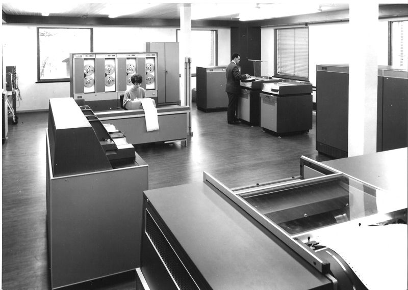
                          In the early '60s, we used a system called Numerical Master Geometry, ran it on an ICL 1905 main frame computer (using all of it for a single run). With the system, we defined 3-D shapes like wings, cockpits, fuselage etc. Forerunner of CAD ??

                          https://pdfslide.net/documents/numerical-master-geometry.html

                          icl1905computer.jpg

                          #562288
                          duncan webster 1
                          Participant
                            @duncanwebster1

                            Probably got the processing power of a wrist watch today

                            #562291
                            Another JohnS
                            Participant
                              @anotherjohns
                              Posted by duncan webster on 10/09/2021 22:04:21:

                              Probably got the processing power of a wrist watch today

                              I do remember going to the then supercomputing centre (RUS) in Stuttgart, when people there were research buddies, and, in one bar area, there was a liquid-cooled CRAY (CRAY-2??) computer, wiring visible through the plexiglass covers, and it was used as a table for standing around drinking beer, the power supply bench surrounding the cray CPU was, well, a bench for sitting on.

                              The chief buddy of mine said something like "it's only a couple of years old, but cost too much to run, so it was re-purposed".

                              I'll tell you – it was *very* weird using it to hold pitchers and glasses of beer while we stood around socializing…

                              I did have a nice little SGI Onyx-2 computer (a purple cube about desk height) that I got from a department that did not like the $10,000 (CAD) yearly maintenance fee, so I used it for a year or two off-contract. Eventually, my early Linux computers worked faster, but were not nearly as neat, and it was sent to "crown assets" for recycling or selling on.

                              Changed times… for the better in my opinion

                              #562295
                              brian jones 11
                              Participant
                                @brianjones11

                                Indeed wise words here

                                I support the notion – forget 2D tech drg, it will only confuse you

                                Start with 3D concepts from the outset

                                • you make sketches on a plane – normally XY – and these must be closed to make shapes that can fill and become a face (an exception here is when we create a path – later)
                                • no extra lines, points, duplicates on top, lines crossing without intersection They wont extrude – non manifold , line crossings will give you grief – dont do it. Your 3D CAD app probably warns you not to break these rules
                                • A shape/face in 2D has zero thickness and is unrealisable. Dont leave tabs in your model. Dont have two shapes touching each other
                                • When you extrude a face it becomes a solid in 3D and the original face is the datum
                                • Extrusion is always normal to the face and the face has a direction

                                For example

                                Imagine a cup drawn with a cylinder and a bottom face. The surfaces have zero thickness. Indeed your 3D CAD app should not allow you to draw it. However If you sketch your cup with a 2D circle base and an inner circle for the wall thickness, you can extrude the inner circle (bottom) first and the cylindrical wall next and you will have a 3D solid – a real cup with an open top.

                                If you do it the other way round you end up with a tube

                                So following conventional 2D CAD practice will give you grief

                                FYI from above this is how CAD was enabled on screen and on pen plotters (remember those HP?)

                                https://en.wikipedia.org/wiki/Bresenham%27s_line_algorithm

                                Edited By brian jones 11 on 10/09/2021 23:50:44

                                #562301
                                JasonB
                                Moderator
                                  @jasonb
                                  Posted by brian jones 11 on 10/09/2021 23:47:58:

                                  For example

                                  Imagine a cup drawn with a cylinder and a bottom face. The surfaces have zero thickness. Indeed your 3D CAD app should not allow you to draw it. However If you sketch your cup with a 2D circle base and an inner circle for the wall thickness, you can extrude the inner circle (bottom) first and the cylindrical wall next and you will have a 3D solid – a real cup with an open top.

                                  If you do it the other way round you end up with a tube

                                  Or you can draw one circle and extrude giving you a solid cylinder, draw a second circle on the top and cut extrude to the depth of the inside, same amount of ops eg two circles and two extrudes and the same result. Or one sketch which is in effect a half section and revolve it.

                                  A lot will depend on the part being drawn as to which method is best, eg revolve works best with a posh shaped tea cup but the extrude is OK for a plain mug.

                                  Also starting on XY is not a general thing, I tend to start so that the part will have the orientation that I want when viewed from the default angle or relative to something on the main assembly eg crankshaft axis as it makes subsequent assemblies easier if things line up as soon as they are brought into the assembly. If drawing a part that will go into CAM for CNC machining I'll choose an orientation that puts it on the machine table with suitable XYZ for machining.

                                  #562431
                                  brian jones 11
                                  Participant
                                    @brianjones11

                                    Indeed JB there are always many ways to skin a cat in geometrical drg

                                    the cup was simple to show that zero thickness shape dont work in 3D

                                    course I may be prating from my freckle as there;s something called surfaces lurking in my tab bar

                                    thats the trouble with solo on line learning much of the dubious tutorials are outdated and things change

                                    if you are in a design office you get the latest buzz

                                    #562485
                                    Nigel Graham 2
                                    Participant
                                      @nigelgraham2

                                      It is true by basic geometry that a line has no width or thickness, but it is not necessarily true that a line cannot be used to form a thin wall in CAD.

                                      It requires simply giving the line a specific width, which may be only a very small fraction, effectively turning it from a geometrically pure line to a rectangle, for example.

                                      In TurboCAD at least – which unlike as some people seem to imply, IS 3D-based – that is one of its ways to produce an extruded "solid"; but with two important caveats. Firstly the location is governed by the wall's neutral axis; secondly if the line is a full boundary such as a circle or polyline, the extrusion is "solid".

                                      So drawing our example mug from a library cylinders or extruded circles, still requires creating a solid cylinder then subtracting from it a concentric inner one, stepped up by the base thickness.

                                      '

                                      One point about TurboCAD and I do not know if this applies to other CAD makes, is that it seems to use at least three ways to generate solids, giving each different characteristics hence different, often unexpected, reactions to subsequent editing.

                                      To be fair though I say "seems" because I have probably missed something by very rarely using 3D CAD anyway. Wasting 100s of hours trying to learn it to no more than a very basic level made me realise it is both a major, very advanced computing skill, and of very limited, practical engineering value to me.

                                      Perhaps the first choice is not of CAD make, but basic type. It is not a fashion-statement, so however heretical this may be to some, you may need or merely want for your own engineering an advanced isometric-first package, or a reasonably comprehensive orthographic-only version.

                                      Then you need consider if you will be able to learn it. You may find it very straightforwards or an uphill battle, depending on the programme itself, the embedded, supposed "Help" menu, the available tutorial material – and your own ability especially if a CAD first-timer. I found the basic teaching material sold with the software very good – not a wretched video of an expert showing off, but a proper pdf manual, on a CD.

                                      My choice? A programme whose big advantages over other makes, include giving both options very easily. So I occasionally try very simple isometric drawings as academic exercises, but use its direct orthographic "side" for all real, practical purposes.

                                      '

                                      Remember though, it's what we make that counts. The lathe is necessary, but the CAD programme may help.

                                    Viewing 17 posts - 1 through 17 (of 17 total)
                                    • Please log in to reply to this topic. Registering is free and easy using the links on the menu at the top of this page.

                                    Advert

                                    Latest Replies

                                    Viewing 25 topics - 1 through 25 (of 25 total)
                                    Viewing 25 topics - 1 through 25 (of 25 total)

                                    View full reply list.

                                    Advert

                                    Newsletter Sign-up