Strange – Despite that "house-keeping" I mentioned above I still had what should have been a straightforward drawing freeze, my vehicle's GA, for a worrying but short time. It is very easy in TurboCAD to produce all manner of hidden, surplus fragments so there might be some in there.
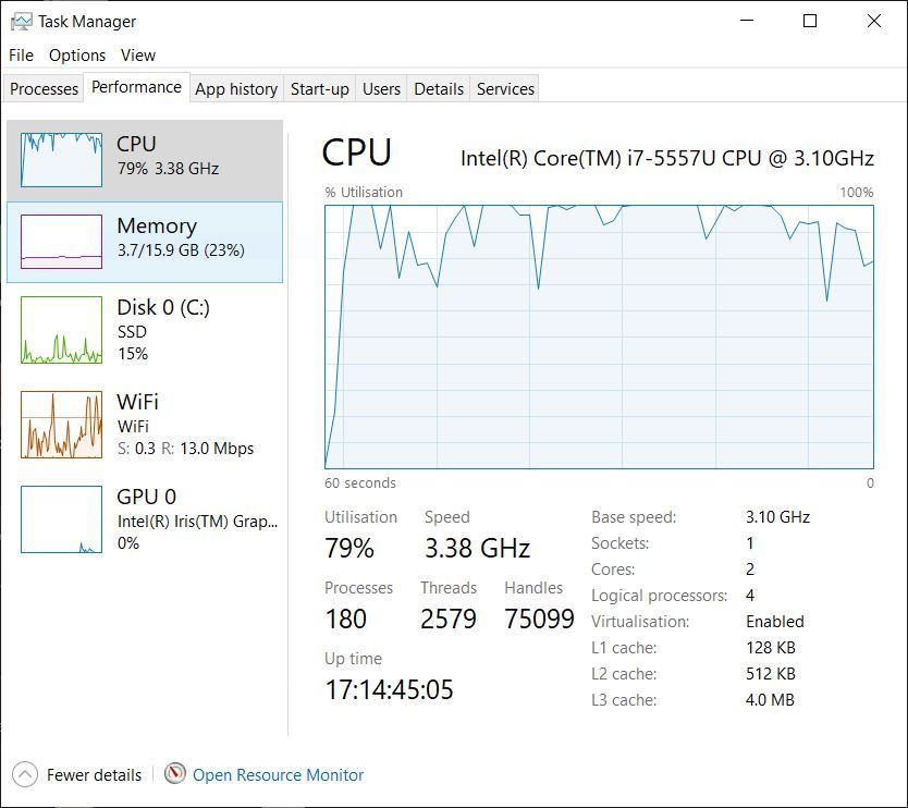
By experiment I ran Task Manager's performance graphs while opening that GA, probably my largest drawing.
There were expectedly two big CPU peaks as the programme then drawing opened, but it registered very low memory use, and when I highlighted an object and moved it, the graphs barely flickered.
I thought the size of the drawing – 4 orthographc elevations – might be too big but it seems <400kB.
Jason, Nicholas –
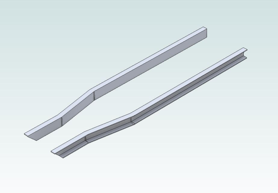
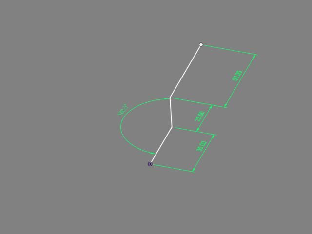
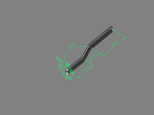
Thank you for the hints, but I'm afraid I cannot produce what you say is easy, that pair of cranked chassis rails. I could draw them as Extruded sections if they were straight and parallel to an axis, but not at angles.
Jason –
I think you are using Alibre and perhaps non-axial figures are easier in that. You are right – the rails are bent only in plan (I hope the real ones are, too!).
'
Nicholas –
What did you use there?
TurboCAD Deluxe 19 has no "sweep" command, according to its manual. The TC Users' Forum sometimes refers to "rail sweep", but I don't know what that does.
I don't think it allows dimensioning in full 3D as you have, only on elevation views. TC has associative dimensions that follow object changes, but I do not know if reciprocally.
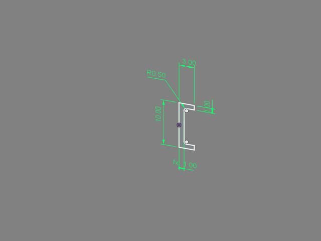
The exercise proved I cannot draw in TC complicated items like those cranked channels from extrusions of the cross-section. Instead, I would have to work from the component's plan. The real metal is 50 X 25 X 5mm, but I used inches to suit the model itself, rounded to 2 X 1 X 0.2 inches. SO:
– 1) A thickness-extruded, 8-sided Polyline; full length, 1" wide X 0.2" deep.
– 2) A copy moved to one side, dropped it 1.8" (the Reference Points are in mid-metal). These are the flanges
– 3) A second copy, moved aside, Exploded edited and re-united as a Polyline 0.2" wide X 1.6" deep (the web).
– 4) Assemble the flanges to the web.
– 5) Copy the whole caboodle, slide the copy away, invert it, calculate from a plan-view dimension the spacing adjustment.
– 6) Calculate moving both rails to put the nearest corner as a datum on round-numbered co-ordinates: probably entailing some geometrical construction, because the combined Reference Point is somewhere in the middle..
This omits the flange tapers and roots as merely needless complexity. Even so, it proved too difficult and I realised I cannot draw the rest of the vehicle, not in 3D.
'
Forming that long bevel at the front needed:
– Extruding a long bar from a triangle, swinging it horizontal, Assembling it to the rails.
– Copying it, moving the copy aside.
– Subtracting the first prism from one rail – this also deletes the prism.
– Returning the copy for the second rail's subtraction.
(TurboCAD's version of "Cut" is "Object Trim", working only in 2D.)
Similarly I don't think it's possible to Extrude a solid to another, only extend lines to them. Normally to ensure things meet in 2D I draw them over-length and Object Trim them back. In 3D I need calculate their right lengths.
I calculate co-ordinates and relative moves from points on the drawings because I cannot understand the extraordinarily complicated Work-plane and Co-ordinate systems. I don't know if this complexity is just in TurboCAD or 3D CAD generally.
'
Sorry, but the concepts and methods you show are new to me, don't apply to the CAD version I have, and are more advanced than my level. I used to think I could learn 3D CAD!
Nigel Graham 2.


