Fusion 360 Turn: Tool location/position

Advert

Fusion 360 Turn: Tool location/position

Home Forums CAD – Technical drawing & design Fusion 360 Turn: Tool location/position

Viewing 7 posts - 1 through 7 (of 7 total)
  • Author
    Posts
  • #536189
    Richard Evans 2
    Participant
      @richardevans2

      Hi All,

      I have a bit (not loads) of CNC experience and I'm investigating CAM for turning in F360. All the videos I've seen show the tool position as being behind the workpiece, and when I add a tool in my test project, that's where it is. I would like the tool to be in front of the work, where it is on my lathe (Denford Orac) so that I can clearly see what the toolpath looks like in simulation etc..I can't find a way of doing this.

      I can't get my head around the tool at the rear (I know rear-mounted tools are used!)- surely Fusion isn't expecting the lathe to run in reverse?

      What am I missing? I can change so much in Fusion- why not this?

      Thanks for any advice,

      Richard

      Advert
      #21340
      Richard Evans 2
      Participant
        @richardevans2
        #536205
        JasonB
        Moderator
          @jasonb

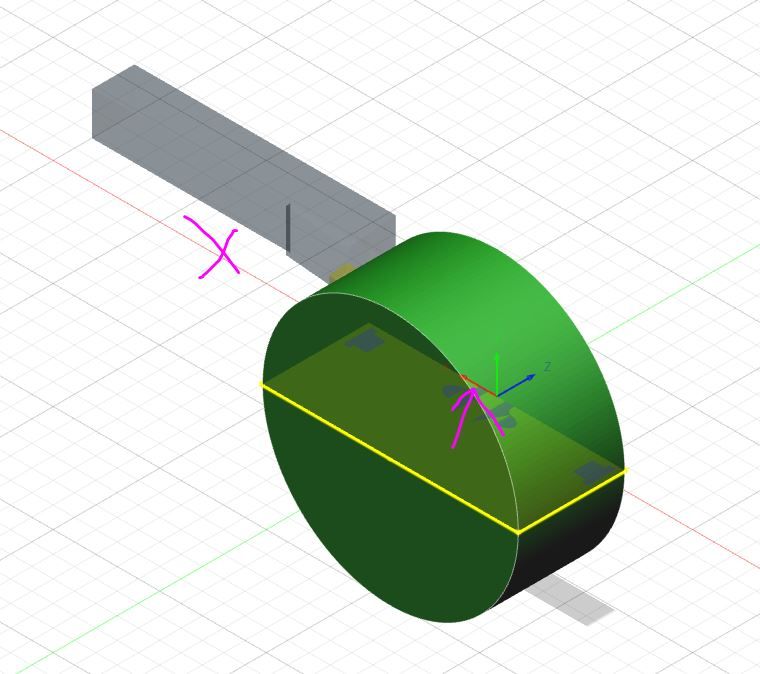
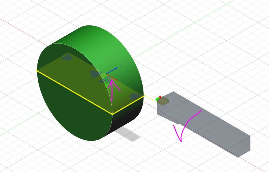
          When you do the setup of the stock make sure X is facing towards you then the tool comes up on the correct side. You can also edit the tool for forward or reverse rotation

          f360turn1.jpg

          f360turn2.jpg

          Should then cut like this view rotated as if looking fronm rear tailstock end.

          Edited By JasonB on 26/03/2021 09:52:44

          #536314
          Emgee
          Participant
            @emgee

            Richard

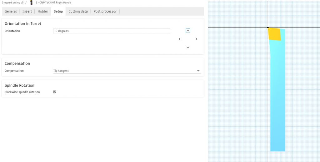
            When you select the tool use the Setup option in the Tool menu to orientate the tool correctly, you can Edit the tool after selection if you need to change anything.

            fusion tool setup.jpg

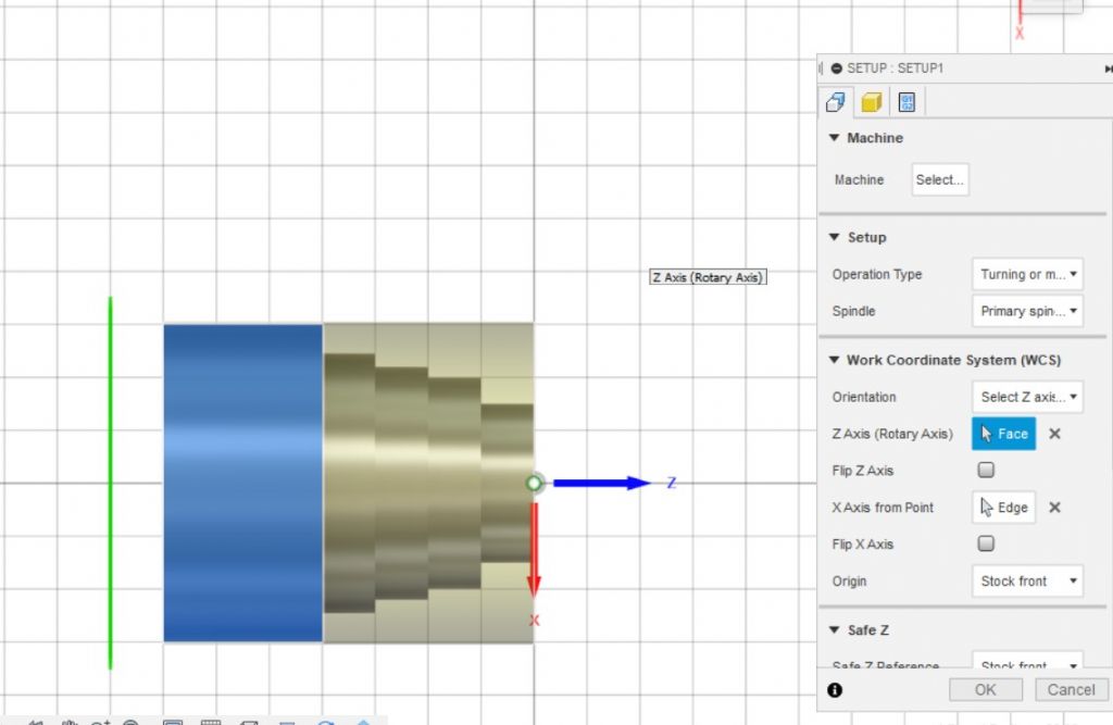
            Also when completing the work setup you can Flip the WCS direction for Z and X axis.

            Emgee

            fusion wcs settings.jpg

            #536365
            Richard Evans 2
            Participant
              @richardevans2

              Thanks Jason and Emgee- that issue seems to be sorted.Now something else (of course). I have a simple test piece- just a conical shape. The simulation looks fine in Fusion, but in Mach, the shape is wrong and there are loads of large loops in the toolpath. Any idea? Obviously, I'm using the Mach 3 Turning post in Fusion.

              As an aside, it's the first time I've looked at Mach for a while, it looks pretty dated compared to modern software. I use it regularly on the Triac mill, but these are routines I wrote years ago using Sheetcam, I haven't tried to do anything new in Mach fora very long time!

              Thanks again

              Richard

              #536369
              Emgee
              Participant
                @emgee

                Check which mode, Diameter or Radius, the program is written in matches the setting in Mach.

                Emgee

                #536469
                Richard Evans 2
                Participant
                  @richardevans2

                  Thanks Emgee, but that didn't do it.

                  I sorted it by going to Config-Ports and Pins- Turn Options, and unticking the 'Reversed Arcs in Front Posts' option. This apparently is related to the front toolpost location as distinct from rear.

                  Now I just need to sort out a few options and settings in Fusion…….

                  Richard

                Viewing 7 posts - 1 through 7 (of 7 total)
                • Please log in to reply to this topic. Registering is free and easy using the links on the menu at the top of this page.

                Advert

                Latest Replies

                Viewing 25 topics - 1 through 25 (of 25 total)
                Viewing 25 topics - 1 through 25 (of 25 total)

                View full reply list.

                Advert

                Newsletter Sign-up