Old School Drawing Exercises and 2D CAD

Advert

Old School Drawing Exercises and 2D CAD

Home Forums CAD – Technical drawing & design Old School Drawing Exercises and 2D CAD

Viewing 25 posts - 1 through 25 (of 146 total)
  • Author
    Posts
  • #21319
    SillyOldDuffer
    Moderator
      @sillyoldduffer
      Advert
      #483268
      SillyOldDuffer
      Moderator
        @sillyoldduffer

        Another recent thread asked which free 2D CAD package could draw a spoked wheel. The question led to a number of recommendations, ranging from do it manually to buy a special Gear drawing package that outputs G-Code so the part can be made by a CNC machine.

        Actually, almost any CAD tool could do the job. As can traditional drawing board methods. After all CAD is just old drawing methods on steroids, power assisted, turbo charged, semi-automatic, and all modern conveniences. First problem is CAD software has to be learned, second is they have to be applied to create results. Applying tools once they been understood is hard too! Even simple tools like files are difficult to use properly, and imagining a shape buried inside a lump of metal – design – is another skill again!

        Draughtsmen were trained thoroughly and much of it remains relevant. Their 19th century exercises make one think!

        In that spirit, I offer a couple of examples. In the CAD package of your choice, or paper and pencil, how easy or difficult is it to replicate them?

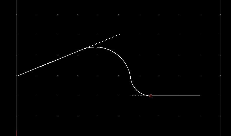
        First, two lines at an angle (any angle), connected by a pair of reverse curves. This is a common problem laying out railway lines, where the line is run around an obstacle rather than build expensive tunnels or bridges. In this example the tight curve is radius = 1 and the broad curve is 1.75

        reversecurve.jpg

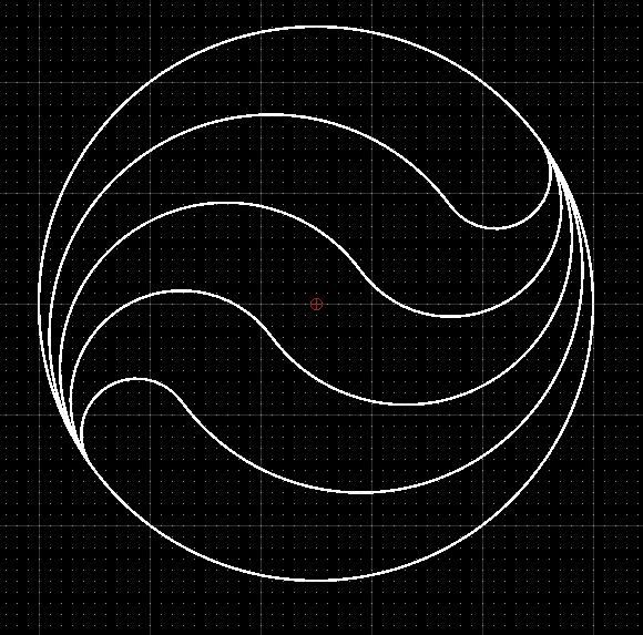
        Second example is decorative:

        equalcircles.jpg

        Not difficult except the swirls are 36° off horizontal.

        Bonus question, are the five curvy segments all the same area or not? Can your CAD tool measure areas?

        Dave


        Edited By SillyOldDuffer on 01/07/2020 11:03:21

        #483274
        JasonB
        Moderator
          @jasonb

          Always think that if you know the old school ways it makes CAD easier, my swirls at 45 deg as I could not be bothered to hunt down the adjustable set square

          20200701_113327[1].jpg

          20200701_113318[1].jpg

          #483280
          JasonB
          Moderator
            @jasonb

            Alibre has answered the bonus question, I'll post the answer later after a few other have posted.

            #483285
            Anonymous

              Good grief, SoD must be really bored!

              Andrew

              #483286
              JasonB
              Moderator
                @jasonb

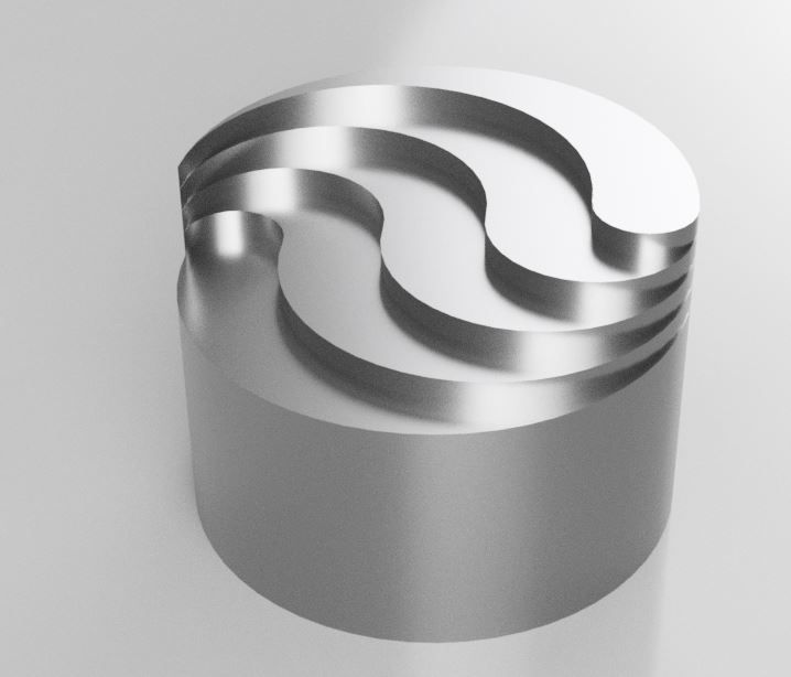
                If Dave is bored this afternoon then maybe he could have a go at machining his spiral pattern on the end of some bar and see if he can get it to look like thisdevil

                daves spiral r1.jpg

                #483288
                Bazyle
                Participant
                  @bazyle

                  Sorry you both fail on the railway lines one – no transition curves laugh

                  #483291
                  Nigel Graham 2
                  Participant
                    @nigelgraham2

                    Draughtsmen (and most were men, though my Mum was a tracer in a drawing-office), were not only taught drawing thoroughly, but also how their creations would be made. They usually started as apprentices, and ones who back far enough were expected even to do things like making accurate cubes by chisel and file – despite the firm paying good money for the shaper and mill.

                    I have seen CAD examples that must have been real so-and-sos in the workshop, CNC- or conventional, thanks not to using CAD but to the draughting tool taking precedence over the engineering tool. And we all know just how difficult some cars can be to service, thanks to poor or no consideration of accessibility to what should be accessible, such as lamps.

                    Where does the fault lie? Poor training? Or good training but skewed too much to theory and design-tools? An assumption of the "Computer says X so X must be right" ?

                    Some of the old-style, professional, orthogonal GA drawings we see now via our hobby scale-replicating early machinery, or preserving the full-size, were fantastically detailed, needing considerable skill and experience over many days of patient work. These can still be produced in CAD – most of such a drawing is only standard lines, simple shapes and hatching, just lots and lots of them – and much more quickly.

                    The experience CAD user is no less skilled at draughting than his or her manual predecessor for the same level of drawing complexity – possibly more so. CAD can do awkward things like merging arcs and plotting pitch-circles and arrays, but it is not intuitive. Nor very efficient if it demands creating an isometric model then taking the orthogonal views from that; but even before the forbidding complexity of 3D, CAD adds a deep layer of skill of its own even just to stich a few basic shapes together.

                    (Some CAD makes, including TurboCAD, offer a straight orthogonal/isometric choice, even if the publishers appear not to know the word for a 2D drawing. Others, including Fusion 360 and Alibre, seem to insist 3D-first. Yet the workshop needs orthogonal elevations, not pretty pictures – though the fitter, operator and repairer need the isometric assembly-drawings.)

                    Yes, the skill at the keyboard, parallel-motion board or T-square on elm board is important, and may be very high-level, but is the intermediary.

                    What really count are the skills of designing, and the skills of making.

                    #483293
                    JasonB
                    Moderator
                      @jasonb
                      Posted by Nigel Graham 2 on 01/07/2020 12:48:51:

                      (Some CAD makes, including TurboCAD, offer a straight orthogonal/isometric choice, even if the publishers appear not to know the word for a 2D drawing. Others, including Fusion 360 and Alibre, seem to insist 3D-first. Yet the workshop needs orthogonal elevations, not pretty pictures – though the fitter, operator and repairer need the isometric assembly-drawings.)

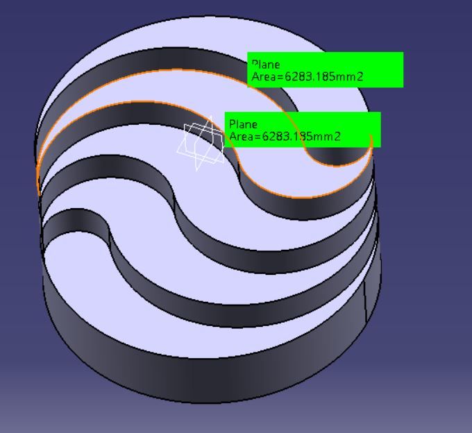
                      Both F360 and Alibre start any item with a two dimensional "sketch" eg you draw one elevation, then the extrusion is really nothing more than adding another elevation to give the part depth just as a drawing side elevation would give depth to the front view.

                      Dave's part I showed above was just a series of three arcs on a two dimensional plane for each area which I chose to give different heights to.

                      #483300
                      JasonB
                      Moderator
                        @jasonb

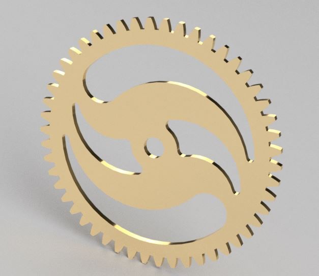
                        Another one for you to have a go at machining Davewink

                        daves gear.jpg

                        #483301
                        Dave Smith 14
                        Participant
                          @davesmith14

                          Areas are all the same.me1.jpg

                          #483302
                          Gary Wooding
                          Participant
                            @garywooding25363

                            Pretty easy with Fusion, and the areas are equal.

                            mecadprob.jpg

                            #483308
                            SillyOldDuffer
                            Moderator
                              @sillyoldduffer

                              Posted by Nigel Graham 2 on 01/07/2020 12:48:51:

                              (Some CAD makes, including TurboCAD, offer a straight orthogonal/isometric choice, even if the publishers appear not to know the word for a 2D drawing. Others, including Fusion 360 and Alibre, seem to insist 3D-first. Yet the workshop needs orthogonal elevations, not pretty pictures – though the fitter, operator and repairer need the isometric assembly-drawings.)

                              Yes, the skill at the keyboard, parallel-motion board or T-square on elm board is important, and may be very high-level, but is the intermediary.

                              What really count are the skills of designing, and the skills of making.

                              Pendant alert! Although I know what he means I'm not with Nigel's use of the word 'orthogonal'. Might explain why publishers don't use it much. It doesn't appear in my various Technical Drawing books either (All at least 40 years old, so maybe I'm out of date!).

                              Pretty sure Nigel means orthographic drawings, named from the technique of orthographic projection, which is the best way of technically representing a three dimensional object on a two dimensional medium like paper. It typically consists of three views of the same object, from the top, side and front. The builder performs the mental gymnastics needed to create the real thing in the workshop. Isometric, Perspective and other projections can be produced from orthographic drawings to create an impression of the 3D reality. Any 2D drawing package can do projections because the user can create them himself. They're all 2D fibs because paper is flat and there is a better way – 3D.

                              3D modelling is very different. Objects are modelled not drawn. They aren't isometric drawings or orthographic projections. Instead models exist as virtual solids with creators working in height, width and depth simultaneously and from any angle. Models can be rotated or sliced at will from any direction.

                              Models aren't limited to dimensions either – materials can be specified, allowing weight, strength, heat-flow, electrical resistance and many other real world characteristics to become intrinsic. Plus many models can be assembled together in cyber-space, thus proving the real world objects will too. I'd argue design errors can be spotted faster in 3D than in 2D – features ambiguous in 2D are obviously wrong when seen in 3D.

                              Modern manufacturing may not require 2D drawings at all; chaps working professionally from 2D drawings are becoming rarer, because – if CNC can do the job, CNC is cheaper. But when 2D drawings are needed for production or prototypes they're easily generated from 3D models, it's not a problem.

                              Learning to use 3D is hard work at the best of times. Expecting 3D modelling to be a form 2D drawing is a recipe for disappointment. 3D needs another mindset. Once mastered 3D is truly wonderful for designing complex objects. Less useful for simple jobs, much of what I do is scribbled on the back of an envelope.

                              Dave

                              #483324
                              Michael Gilligan
                              Participant
                                @michaelgilligan61133
                                Posted by SillyOldDuffer on 01/07/2020 14:47:48:

                                Pendant alert!

                                .

                                dont know

                                Dangling from a thread ?

                                Incidentally … Orthogonal simply means ‘at right angles’ or ‘mutually perpendicular’

                                MichaelG.

                                #483334
                                SillyOldDuffer
                                Moderator
                                  @sillyoldduffer
                                  Posted by Michael Gilligan on 01/07/2020 16:03:16:

                                  Posted by SillyOldDuffer on 01/07/2020 14:47:48:

                                  Pendant alert!

                                  .

                                  dont know

                                  Dangling from a thread ?

                                  Incidentally … Orthogonal simply means ‘at right angles’ or ‘mutually perpendicular’

                                  MichaelG.

                                  Not to us geeks : In computer programming, orthogonality means that operations change just one thing without affecting others.

                                  What I dislike about computer-speak is the constant disappointments. Orthogonality is conceptually related to 'Loose Coupling', which has nothing to do with wife swapping. No joy with 'Back-end Penetration Testing' either, and that one is dangerous to Google!

                                  Dave

                                  #483341
                                  SillyOldDuffer
                                  Moderator
                                    @sillyoldduffer

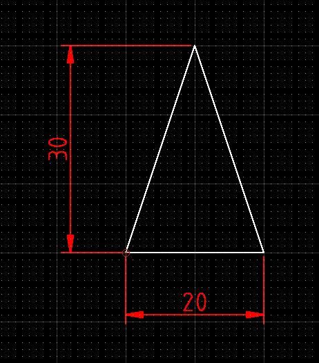
                                    Another Geometrical Drawing. What's the radius of the largest circle that can be drawn inside this isosceles triangle? Score double for solving it with only a compass.

                                    inscribedcirc.jpg

                                    Dave

                                    #483349
                                    Michael Gilligan
                                    Participant
                                      @michaelgilligan61133
                                      Posted by SillyOldDuffer on 01/07/2020 17:23:12:

                                      Posted by Michael Gilligan on 01/07/2020 16:03:16:

                                      […]

                                      Incidentally … Orthogonal simply means ‘at right angles’ or ‘mutually perpendicular’

                                      MichaelG.

                                      Not to us geeks : In computer programming, orthogonality means that operations change just one thing without affecting others.

                                      […]

                                      .

                                      If I try really hard … I can just about believe that there may be some underlying logic in that abuse of the English language : If a thing is considered ‘uni-axial‘ then changing it has no effect upon things that are orthogonal to it.

                                      [or something like that]

                                      MichaelG.

                                      #483357
                                      Anonymous
                                        Posted by SillyOldDuffer on 01/07/2020 17:23:12:

                                        Not to us geeks : In computer programming, orthogonality means that operations change just one thing without affecting others.

                                        No wonder the softies miserably failed to create a working track 'n' trace application. It used to be said that the ideal was an English-like programming language; to which the riposte was that all it would prove was that softies couldn't write English.

                                        Andrew

                                        #483384
                                        DC31k
                                        Participant
                                          @dc31k
                                          Posted by SillyOldDuffer on 01/07/2020 17:40:18:

                                          Score double for solving it with only a compass.

                                          If you can solve it using a magnetic thing, surely that deserves considerably more than double.

                                          If you can solve it using a pair of compasses, that also deserves more than double as drawing the straight lines that form the angle bisectors and whose intersection defines the inscribed circle centre is quite challenging using an instrument for drawing circles.

                                          Referring back to the original challenge, I am dubious that any railway would be constructed from simple circular arcs tangent to straight lines. AIUI, transition curves are always necessary (and drawing those, whether manually or on a computer, is somewhat tricky).

                                          #483397
                                          SillyOldDuffer
                                          Moderator
                                            @sillyoldduffer
                                            Posted by DC31k on 01/07/2020 20:49:10:

                                            Posted by SillyOldDuffer on 01/07/2020 17:40:18:

                                            Score double for solving it with only a compass.

                                            If you can solve it using a magnetic thing, surely that deserves considerably more than double.

                                            If you can solve it using a pair of compasses, that also deserves more than double as drawing the straight lines that form the angle bisectors and whose intersection defines the inscribed circle centre is quite challenging using an instrument for drawing circles.

                                            Referring back to the original challenge, I am dubious that any railway would be constructed from simple circular arcs tangent to straight lines. AIUI, transition curves are always necessary (and drawing those, whether manually or on a computer, is somewhat tricky).

                                            I plead not guilty to both charges, M'Lud.

                                            A compass is a drawing instrument, also known as a Pair of Compasses, but 'Compass' in this context is correct.

                                            When there's plenty of room to lay out a railway line there's no need for transition curves and few early railways had them. My example didn't give a scale, but if the radius of the tight curve is a mile, or even a kilometre, I suggest there's no need for transition curves.

                                            But the point is a good one. Laying out a practical railway the design of curves is complicated – it's necessary to take trains safely round tight curves as fast as possible.

                                            Question for transition curve experts: what form should my reverse curve example take on a standard gauge line if the small radius is 100 metres? And what speed limit should be applied if the line is laid flat? Even more difficult, what improvement can be obtained by applying super-elevation, and what's the optimum tilt assuming the train normally averages 70mph?

                                            Dave


                                            Edited By SillyOldDuffer on 01/07/2020 22:02:10

                                            #483409
                                            pgk pgk
                                            Participant
                                              @pgkpgk17461

                                              70mph round a 100 metre curve? I'd guess you're tilting it 90 degrees and fitting ejector seats…

                                              pgk

                                              #483428
                                              Georgineer
                                              Participant
                                                @georgineer

                                                When I did a course to learn Autocad a few years ago (having learned my draughting the old fashioned way) I was actually marked down for blending my curves too accurately! Our drawings were marked by overlaying them with a master drawing supplied to our lecturer by City and Guilds, and I lost marks because mine wasn't an exact match. I pointed out that my blending was smoother than theirs, so he took it up with C & G. Their response was that I shouldn't be able to do that at level 2 and that their marking scheme stood.

                                                Fortunately our lecturer was a very determined man, and took it as far up their hierarchy as he needed to. Eventually they conceded that doing it better than the minimum required wasn't actually a fault, and I was awarded full marks.

                                                George B.

                                                #483432
                                                Nigel Graham 2
                                                Participant
                                                  @nigelgraham2

                                                  My wretched typing! I'd about finished this when yet again I hit an unknown key-combination and deleted it.

                                                  Orthographic! Yes of course! Thank you gentlemen for the correction! Same root though.

                                                  Of course I am aware that CAD calls the 3D images "models", but TurboCAD's view-changing tool offers two types of view and calls one isometric. I forget the other.

                                                  I am also well aware of the industrial practice now being taken up in some ways by model-engineers, of drawing-files translated straight to CNC-machine drivers.

                                                  '

                                                  Really, for us amateur engineers the choice of whether to use CAD, and to what extent, is by budget, time, preference, learning-ability and indeed interest.

                                                  First we are assuming designing our own projects, rather than sticking to published ones; and considering their complexity. This was my starting-point, as my main project's source is merely a few scrappy old trade photographs from 1908; and I bought a copy of TurboCAD 19 Pro.

                                                  Next, unless you have a particular gift for learning extremely difficult and unintuitive software, which I do not, it can take a formidable time to grasp sufficient CAD experience just for simple orthographic drawings adequate for your own purposes.

                                                  3D-model drawing adds greatly to the complexity; and when designing for yourself, you need ask why lumber yourself when you actually make the parts from 2D drawings. The one advantage I see, was that CAD enables 3D models to help determine complete assemblies. This too, helped sway my decision.

                                                  However, as engineers we should be able to visualise a 3D assembly from 3 orthographic views – depending on its nature.

                                                  So why 3D CAD for own drawings for own projects in own workshops…?

                                                  The only answers I can see are that either you have the desire, time and ability to learn it, or you've bought a CAD package that gives you no choice!

                                                  If we buy CAD because we want to design our projects, presumably we can already create engineering-drawings of appropriate standard. The trap is that of trying to learn the CAD package taking much longer than we would have spent drawing the project manually.

                                                  I bought TurboCAD but really, that it lets me draw a 3D image of, say, my engine's crankshaft does not mean I have to do so. I want to make a real crankshaft, not a pretty picture of one, and after untold hours of struggle better spent actually designing and making the engine, I was just about capable of a pretty picture of the shaft. By then I had made it, to a CAD drawing but orthographic, dimensioned and set out from the orthographic GA.

                                                  I did try other CAD packages.

                                                  I have a copy of AutoCAD 2000, which is 2D only I think, but no manual for it.

                                                  I found Fusion 360's brashness off-putting, and it assumes prior CAD-principles knowledge – to be fair, they all do.

                                                  I tried Alibre but I missed two episodes of the MEW serial. Why buy and learn a complete new package when I'd already bought TurboCAD? I thought the magazine series would make it easier to learn, than trying to teach myself what I already had. So I abandoned Alibre too – which took its publishers months to understand. Luckily, I already have a scribing-block.

                                                  Both Fusion and Alibre are based on 3D- model first – I do not use a 3D CAD/CAM system at home, so regard 3D as nice-to-have, but of limited use, extremely difficult and time-consuming to learn and frankly, not really necessary. It is for brochure artwork, not workshop drawings.

                                                  The only useful 3D images I have drawn were two geological diagrams for a caving-club magazine article.

                                                  '

                                                  Training materials?

                                                  TurboCAD's own on-line 'Help' manual is not much 'Help'; and I can't learn from videos. Far better than these is Paul Tracy's CD manual for TurboCAD, a step-by-step pdf primer.

                                                  D.A.G. Brown's general CAD primer has a very dated cover photograph, but does outline the principles of CAD engineering-drawing. Neill Hughes' more modern alternative, which I also own, is sketchier and more for the 3D-artwork people – and despite a British author and publisher, neighbours to France, it insists on calling "metres", "meters".

                                                  '

                                                  So to sum up, CAD can help us but it is not the be-all-&-end-all of model-engineering. Unless you also intend using CNC machine-tools as well, or buying a lot of profiled work-pieces, CAD is only worth buying if –

                                                  you design most of your own projects,

                                                  you need draw them accurately,

                                                  manually drawing them would take much longer than learning the CAD package sufficiently.

                                                  #483434
                                                  pgk pgk
                                                  Participant
                                                    @pgkpgk17461

                                                    It used to be possible to pick up a previous edition of turbocad for around a tenner from Maplins (and way back when one could download version 3 for free). At that price point they were well worth having. I'm no draughtsman or particularly good with the program because i don't use it much but it's great for things like trying to figure the best way to lay out a part or even where to place the machine footprints in your new shed – less messy than cutting out cardboard shapes and sliding them around on a paper plan.
                                                    It's hardly sophisticated CAD but hepful all the same. And these programs can scale the print out over multiple sheets if needed. Which I found useful for making up a set of sheets to carbon a carving design for a headboard. But be careful – I once sketched out some modifications to my architect's preliminary drawings and sent hime a fax of the changes – in real world units that emptied his fax machine with just the odd page showing bits of a line. Doh!

                                                    pgk

                                                    #483441
                                                    JasonB
                                                    Moderator
                                                      @jasonb
                                                      Posted by Nigel Graham 2 on 02/07/2020 01:58:49:

                                                      So why 3D CAD for own drawings for own projects in own workshops…?

                                                      The only answers I can see are that either you have the desire, time and ability to learn it, or you've bought a CAD package that gives you no choice!

                                                      For me the ability to assemble and move all the part on the screen to check for fits and clearances is a big bonus before I cut metal, can't do that with 2D. Once modelled then 2D drawings can be produced to take to workshop.

                                                      Anyone with CNC will also want to take advantage of its 3 (or more) axis of movement so having the part drawn in 3D is needed. Same applies to those with 3D printers either for printing finished items or maybe printing test items before cutting from metal. No paper drawings would be used in this case as straight from screen to memory stick and into machine.

                                                      It can also be handy if you want to know weight or volume of an item which is just a click away even for complex shapes

                                                    Viewing 25 posts - 1 through 25 (of 146 total)
                                                    • Please log in to reply to this topic. Registering is free and easy using the links on the menu at the top of this page.

                                                    Advert

                                                    Latest Replies

                                                    Viewing 25 topics - 1 through 25 (of 25 total)
                                                    Viewing 25 topics - 1 through 25 (of 25 total)

                                                    View full reply list.

                                                    Advert

                                                    Newsletter Sign-up