Dial Test Indicator

Advert

Dial Test Indicator

Home Forums Workshop Tools and Tooling Dial Test Indicator

Viewing 24 posts - 1 through 24 (of 24 total)
  • Author
    Posts
  • #618160
    Richard Marks
    Participant
      @richardmarks80868

      I would appreciate some help as I am having problems looking for a Dial Test Indicator that has a high level of measurement, all I can find is instruments with a maximum range 0f 40 thou, my dial indicator has a range of 1" but cannot be used horizontally to measure the inside of a hole, the only option I can think of is has anybody built or designed a jig that can use a dial indicator in a vertical position to measure the offset in the inside of a hole, I need to know as I had a job and the hole was not regular and I had problems using my own dial Test Indicator as it could have been damaged due to its small range.

      Advert
      #20823
      Richard Marks
      Participant
        @richardmarks80868
        #618162
        Michael Gilligan
        Participant
          @michaelgilligan61133

          Is this the your general idea ?

          **LINK**

          https://www.starrett.com/metrology/product-detail/671

          … seems awful pricey for what it is, but those nice Starrett people have done the design work for you.

          MichaelG.

          #618202
          JasonB
          Moderator
            @jasonb

            Depends on the setup but the co-axial indicators have quite a wide range if movement. They only indicate movement not distance but a quick bit of testing and maths would give you the actual movement for whatever level length is being used.

            I'm mot sure if Michaels link would work with a 1" range of movement as the arc the lever moves in would have it come off the end of the indicator.

            What sort of size hole are we talking?

            #618203
            Michael Gilligan
            Participant
              @michaelgilligan61133
              Posted by JasonB on 22/10/2022 07:04:22:

              […]

              I'm mot sure if Michaels link would work with a 1" range of movement …

              .

              Most unlikely

              But it’s a big improvement over the aforementioned 40 thou

              MichaelG.

              #618204
              David George 1
              Participant
                @davidgeorge1

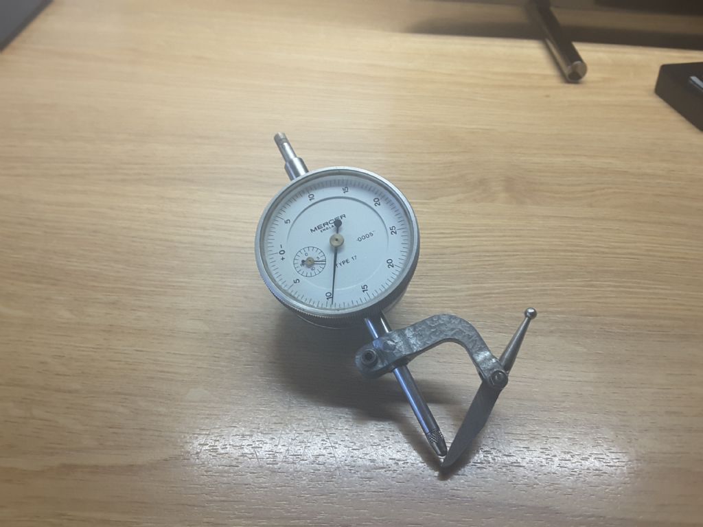
                This is an attachment for my Mercer dial indicator. I have longer fingers which screw into the attachment to give longer depth.

                David

                20210201_074718.jpg

                #618209
                JasonB
                Moderator
                  @jasonb

                  The longer flat area against the end of the indicator would work better but it's like the co-axial one in that it shows a deviation or movement of th eneedle not a measurement and would need to be worked out for each length of finger and maybe a bit of trig thrown in as things are moving in an arc.

                  Does depend on the part and what is available, if the part could be mounted on say a mill table then you only need set one hole true and zero the dial/dro and then set the offset hole true which will give you how much it is offset by simply reading the dial or DRO in this case 40thou would be ample.

                  Edited By JasonB on 22/10/2022 08:59:34

                  #618211
                  Michael Gilligan
                  Participant
                    @michaelgilligan61133
                    .
                     
                    … a rather laboured presentation : Subtitles and Fast Forward advised

                    Edited By Michael Gilligan on 22/10/2022 09:18:55

                    #618217
                    Hopper
                    Participant
                      @hopper

                      If you need to measure a movement or offset of 1", a dial indicator is probably not the best way of doing it. But your description of what you are trying to do is very vague and incomplete. I am totally unsure what you mean by "measure offset inside a hole" or by mounting a dial indicator horizontally vs vertically. You can mount them upside down if you want to. A pic or more thorough description of what you are actually trying to do, and whether it's in a mill or on a lathe etc etc might bring you more helpful suggestions.

                      Further to the above attachments for a dial indicator, Harold Hall did some articles in MEW years ago about making your own. Details and drawings are still available on his website here LINK It's a neat little project. I have been meaning to make a set for years, but have never really had a need for them so never got around to it, yet.

                      #618232
                      Clive Foster
                      Participant
                        @clivefoster55965

                        Bell crank devices are primarily for changing the direction of measurement. They are inherently prone to cosine error so for accurate results the base setting needs to be with the arm perpendicular to the indicator plunger and movement restricted to ± 2.5° to 3° before cosine error sets in.

                        Making the measurement side arm longer increases the physical range but reduces sensitivity commensurately.

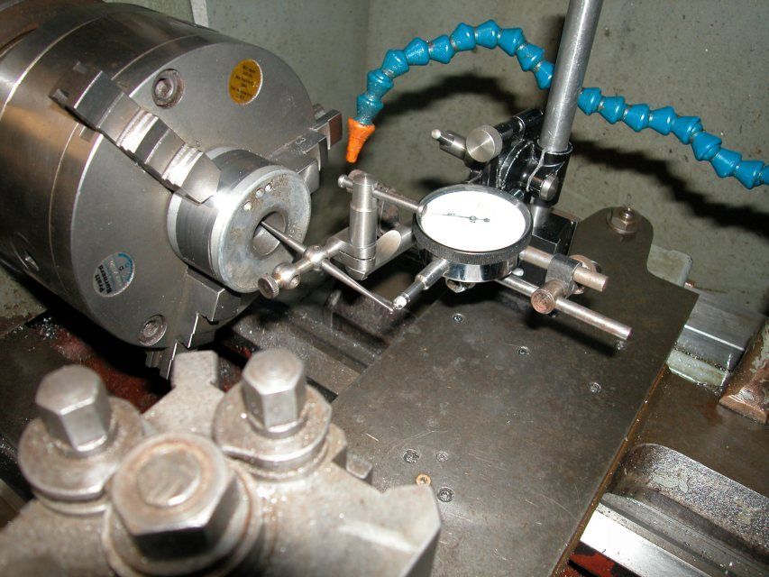
                        Had a slightly similar situation where I needed to get down inside a bore to verify the various errors to ensure that I had enough room to re-machine a podged up taper. I setup the seesaw probe out of a Starrett Last Word indicator kit and an indicator on my lathe cross slide using a magnetic post mount.

                        Something off a KTM enduro bike I think. I was very lucky that the Pratt Bernard precision 3 jaw held it accurately enough to dispense with for jaw games.

                        Indicator Tilting Extension.jpg

                        The Starrett kit uses a back plunger indicator **LINK**

                        https://www.starrett.com/metrology/product-detail/196A5Z

                        so the mounting stalk gets in the way on a set up like this.

                        Using the cross slide feed effectively extend the range considerably. A DRO set up would be most accurate but my cross slide screw and nut are good enough to use as is for better than ± 0.5 thou overall.

                        I see no reason why the measurement arm could not be made rather longer to increase the operating range but the set up is likely to get very twitchy if you go too far. 10 to 1 at 1 thou per division accuracy is theoretically possible using a tenths thou indicator but the chances of it being stable enough to actually use are slim. 2 to 1 is probably OK.

                        The Starrett see saw has small spherical contacts at each end and the plunger indicator has a dome end contact. This increases the angular movement range before cosine error sets in. Calculating the effects is possible but not as easy as it might seem. Size matters! In practice anything significantly more than ± 10° or so has the see saw end running off centre round the plunger end so things start to mis-behave and it all gets a bit fraught.

                        Bottom line is it all worked but I din't want to do it in the first place and, frankly my dears, I'd rather not do it again!

                        Clive


                        Edited By Clive Foster on 22/10/2022 11:07:24

                        #618233
                        Martyn Duncumb
                        Participant
                          @martynduncumb88863

                          Oh dear, maybe it is just me, but I have just tried the link to Harold halls website and it keeps dropping the connection. I will try later today and hopefully it will work again. Has anyone else had a problem?

                          Martyn

                          #618234
                          Michael Gilligan
                          Participant
                            @michaelgilligan61133
                            Posted by Martyn Duncumb on 22/10/2022 11:09:54:

                            Oh dear, maybe it is just me, but I have just tried the link to Harold halls website and it keeps dropping the connection. I will try later today and hopefully it will work again. Has anyone else had a problem?

                            Martyn

                            .

                            Just tried … No joy sad

                            also tried one level up, and that doesn’t connect either

                            MichaelG.

                            .

                            https://www.homews.co.uk/page619a.html

                            https://www.homews.co.uk/

                            https://www.homews.co.uk

                            Edited By Michael Gilligan on 22/10/2022 11:26:04

                            #618237
                            Peter G. Shaw
                            Participant
                              @peterg-shaw75338

                              Harold Hall's dti accessories will be found in:

                              MEW14 (Dec 1992) (or MEW 151/152 (Jun/Jul 2009) for a later version).

                              Also WSP 39, Ch.12.

                              HTH,

                              Peter G. Shaw

                              #618239
                              Neil Lickfold
                              Participant
                                @neillickfold44316

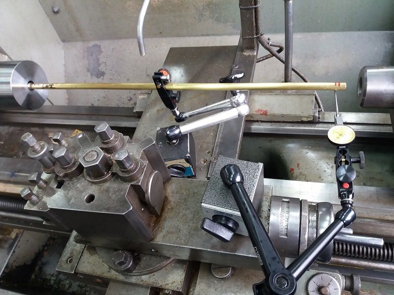
                                I have a long stylus Girod indicator with the small dial. It can get in about 30mm or so just on the stylus. On things with a 40mm hole it can get in as far as you can read the indicator. For getting into very long holes around 250mm deep, I made a pivoting gizmo and use the low press finger indicator with it. It is close to 1:1 ratio. I use this for indicating the bottom of a drilled hole , to align the hole and make the outer true to this hole. I will try and post an image of one of the setups. This is an early one that used a brass tube to keep the weight down and only used the indicator stand end for the pivot. It shows testing at the front of the part checking it's error reading on an area that is known. My latest one uses a piece that has 2 ball bearings in it to reduce pivot drag. In hindsight I probably should have used the type of pivot used in indicator stylus ends.

                                checking-runout-r.jpg

                                #618249
                                Martin Johnson 1
                                Participant
                                  @martinjohnson1

                                  I made a homespun version of the Starrett lever & stylus. I have both 180 and 90 deg levers. There was a design in one of the very early MEW's. Not difficult though – a scrap of ally plate, afew small screws and a some steel rod plus an afternoon's work.

                                  Martin

                                  #618250
                                  Ian Hewson
                                  Participant
                                    @ianhewson99641

                                    Harold’s site worked for me a minute ago with Michael’s links, iPhone and Safari .

                                    Ian

                                    #618261
                                    peak4
                                    Participant
                                      @peak4
                                      Posted by Ian Hewson on 22/10/2022 12:50:34:

                                      Harold’s site worked for me a minute ago with Michael’s links, iPhone and Safari .

                                      Ian

                                      And fine for me from a desktop; it's also a lot faster than when I previously visited, so maybe a server upgrade.

                                      Bill

                                      #618263
                                      Michael Gilligan
                                      Participant
                                        @michaelgilligan61133

                                        Page opens “in the blink of an eye” now

                                        Well done Harold [whatever you did]

                                        MichaelG.

                                        #618265
                                        Richard Marks
                                        Participant
                                          @richardmarks80868

                                          Thank you Gentlemen, I can now work out what to do as it all looks very good.

                                          Richard Marks

                                          #618272
                                          Martyn Duncumb
                                          Participant
                                            @martynduncumb88863

                                            Great, thanks everyone, now got Harold Halls site working very well.

                                            Martyn

                                            #618352
                                            Hopper
                                            Participant
                                              @hopper

                                              But, as I said before, if you are trying to measure 1" of runout in a hole with a dial indicator, there are probably better or easier ways of doing it. Depend on what you are trying to do as to exactly which alternative would suit your needs.

                                              That's why nobody uses the Harold Hall type attachments anymore since lever-type DTI's became commonly available. (They used to be an exotic luxury item until recent times.)

                                              One problem with the Harold Hall and Starrett type attachments is the ball on the end of the lever moves in an arc while the dial inidcator plunger moves in a straight line. So it will struggle mightily to read correctly over a 1" range due to the ball on the end of the lever misaligning with the plunger at each end of the 1" of travel. It was really intended to do the same thing as today's lever DTIs and measure runout of maybe 100 thou or less.


                                              Edited By Hopper on 23/10/2022 13:24:14

                                              #618360
                                              Clive Foster
                                              Participant
                                                @clivefoster55965
                                                Posted by Hopper on 23/10/2022 12:53:46:

                                                That's why nobody uses the Harold Hall type attachments anymore since lever-type DTI's became commonly available. (They used to be an exotic luxury item until recent times.)

                                                Edited By Hopper on 23/10/2022 13:14:12

                                                Not really.

                                                Lever types, originally direct acting and later the modern "fast screw" style, were always the economically priced option. Consider the Unique to explore the insanely cheap possibilities.

                                                But they are fundamentally null indicators so the change in accuracy with probe angle isn't of great import. Verdict developed the pear shape end to largely compensate for such errors. But the measurement range is inevitably small.

                                                The rack and pinion drive used on plungers gives much more range of measurement and, if accurately produced consistent sensitivity over the whole range. Hence it can be used as a reliable measuring device. But the quality of workmanship needed inside has always made them relatively expensive.

                                                There are ways of geometrically compensating for the arcuate movements inherent to the offset lever accessory devices such as those designed by Howard Hall. Although such can be effective they fundamentally rely on first set-up being with the offset lever largely perpendicular to the plunger stem.

                                                In practice its generally considered less than ideal to use a plunger indicator over any extended range. Naturally such use may be quite adequate in many applications.

                                                According to the Inspector Meticulous Union Rules objectively correct practice is to restrict measurements to around ± half a dial.

                                                Fundamentally the proper home of a plunger indicator is in a stand checking variations in production parts, or samples thereof, to verify that factory output is within tolerances. Long travel just makes set up easier and helps get round extraneous lumps of casting et al.

                                                Although a plunger indicator can be used as a decently accurate linear measuring device over its full range there are certain caveats associated with such use that need to be understood when seeking to fully exploit the potential accuracy. Which in general are at a level that is of no import to the work folk like us do at home by such methods given sensibly careful set-up and handling.

                                                I absolutely agree that there are better methods when dealing with longer travels.

                                                Back in the day the firm bought me some uber expensive, optical grating based, Hiedenhain probes when long travel plunger indicators couldn't hack it. The boss figured the probes were worth more than I was!

                                                As is so often the case with tricky measurements. Carefully considered breaking of "the rules" works just fine if you've taken the trouble to understand the rules in the first place.

                                                To quote (who?) :- "Rules are made for the guidance of wise men and the obedience of fools."

                                                Clive says :- "It's hard work becoming wise and makes my head hurt. Most of the time I get along just fine being a fool."

                                                Clive

                                                #618365
                                                Mike Poole
                                                Participant
                                                  @mikepoole82104

                                                  To quote (who?) :- "Rules are made for the guidance of wise men and the obedience of fools."

                                                  I think Douglas Bader said it shortly before losing his legs in a crash, not sure if he was the originator though.

                                                  Mike

                                                  Edited By Mike Poole on 23/10/2022 14:36:18

                                                  #743581
                                                  Neil Lickfold
                                                  Participant
                                                    @neillickfold44316

                                                    I made a bearing pivot some time back.
                                                    It is a housing that is bored through at 16mm to be a neat fit to hold the outer race of a 688 sealed bearings, 8x16x5
                                                    The base of the block is 9.5mm diameter that suited the Noga stand I was previously using with a Brass tube and a hardened disc.
                                                    The block is made from a piece of 7075 Al that was at hand, with the outside of 26mm.
                                                    On the opposite end to the 3/8 shaft section, it is a hole, Ø8mm x 19mm deep. This is for a 8mm dowel pin and is used as a reference for cutting the flats on the body.
                                                    The flats are 19mm x 22mm.
                                                    After the pin is removed, I drilled through with a 13mm drill in the mill, at 10.5mm from the end face and in the middle 19mm flat. So the hole is 22mm long . With an 8mm cutter, cut out the window for the pivot arm in the centre of the 22mm flat, so at right angles to the 13mm drilled hole. The window is 10mm wide and 14mm high. It’s centre line is also 10.5mm from the end face.
                                                    The 10.5mm is not important, just that the material I had was a little shorter than ideal. I kept the rectangular window central to the centre line of the bearing bore.
                                                    It is +-1mm wide with the cutter and +-3mm vertically. Making the slot 10X14
                                                    Instead of boring in the mill, just used the 4jaw and bored in the lathe.

                                                    The inner pivot pin, is made from steel, is 15mm in diameter and total length is 22mm.
                                                    Each end is turned a nice slide fit to the 8×16 bearings and the spigot is 4.95mm long. 0.03mm shorter than the bearing thickness. The bearings measured 4.98mm thick.
                                                    The end is drilled and tap for M6 thread. One end is retained with a domed 6mm hex screw. The other end has a longer screw and a nut. The screw also secured the pivot arm once it length is set, and the nut and washer keep the inner of the race secured.
                                                    The cross hole is done with the 4jaw chuck in the lathe and is centred in the middle of the piece. I bored it 9.53mm through so that it could still use the brass tube pivot rod from the original setup.
                                                    A nylon insert was made that is a neat slide fit into the pivot pin, and has a 6mm hole to suite the 6mm silver steel new pivot arm. It needs to be locked with the side screw to prevent any excessive wobble occurring while being used.

                                                    The bearings are placed on the pivot pin, and with a tube, the outer ring is pushed on, to get the assembly into the middle of the body. I pushed onto the outer race, so that they are both assembled effectively being preloaded towards the centre of the block. This is to make them a bit like an angular contact bearing, so that there is no wobble at the end of the pin once all assembled.

                                                    The pivot rod is made from a piece of 6mm silver steel 590mm long, that was heated, hammered a bit, shaped, then the end hardened and tempered, and polished. The smoother the better. On the same side as the hammered end, is filed flat for the indicator to rest against.
                                                    This new assembly is very free moving, and the pressure from the finger clock, is enough to keep the end in contact with the workpiece.

                                                    I test it on the end of the work piece, a bored area, to see what the reading range is, manually rotating the chuck forward and reverse seeing how it behaves. I find the low point with the cross slide.
                                                    Then when down into the hole, again use the cross slide to centralise in the hole and dial to as close as possible. Repeat the centralising and keep adjusting the chuck as needed. It is not perfect, but can get the end of the hole to within the roundness of the hole , usually less than 0.05mm indicating range.
                                                    I was thinking that I needed a ball arrangement like in DTI pivots etc, but this works very well and has not needed any readjusting of the outer races.
                                                    Neil

                                                    20240723_160441_resized20240723_160514_resized20240723_160521_resized20240723_160537_resized20240725_095153_resized20240725_095326_resized20240723_160435_resized

                                                  Viewing 24 posts - 1 through 24 (of 24 total)
                                                  • Please log in to reply to this topic. Registering is free and easy using the links on the menu at the top of this page.

                                                  Advert

                                                  Latest Replies

                                                  Viewing 25 topics - 1 through 25 (of 25 total)
                                                  Viewing 25 topics - 1 through 25 (of 25 total)

                                                  View full reply list.

                                                  Advert