Myford M – a few random questions

Advert

Myford M – a few random questions

Home Forums Workshop Tools and Tooling Myford M – a few random questions

Viewing 25 posts - 1 through 25 (of 31 total)
  • Author
    Posts
  • #603035
    Alec Gunner
    Participant
      @alecgunner39277

      Having recently bought a 1946 Myford M a few questions have come up, both general to the model and specific to my machine. I had a look through the forum but can't find answers to these particular ones, so, bearing in mind I am a novice, here goes:

      The toolpost arrangement seems odd. I have both the clamp-on type and the 4-way post which are designed to take tooling of up to about half an inch, but the centre height seems too high as anything over about 5/16" (8mm) toolling falls well above the minimum adjustment for centre height. Is there a reason for this? It would also be very convenient to fit a quick-change toolpost to get the height adjustment set up without shims. I am aware of the modification by removing the original cast-in toolpost but has anyone successfully bored out a quick-change toolpost to fit the 1-1/4" original post? I know most are hardened and hence difficult to do this with, but annealing case hardening is possible, or there is an unhardened one from Chronos. Has it been done?

      Whilst wear appears acceptable in most parts, I do have a lot of wear in the half nut with over half a turn of backlash. I have seen the bobbin-type repair approach but am not yet confident enough to attempt that level of work. Has anyone made these for sale? I also have some adjustments to make as there is a bit of end float in the headstock spindle – I have read the instructions (and the notes on adding/changing various bearings) but I can't claim to fully understand the pros and cons of the various approaches. It looks like the starting point is to obtain a suitably sized C-spanner to slacken the bronze collars, but I can't see any castellated nuts?

      I definitely have a missing oiler on the front end of the headstock and my understanding is that since this also serves to lock the bearing and spread it slightly, simply dropping oil down the hole is not a suitable substitute. Any ideas on where to find a suitable oiler or, better still, to find a drip oiler? I can get simple oil cups from RDG but don't actually know what the thread is?

      The whole machine has a wobble. Whilst everything runs true relative to its own reference, the wobble makes it difficult to check what is happening whilst turning. It seems to trace back to the motor – this has the bench-mounted counter-shaft/motor unit so whilst the motor pivots semi-independently, the whole assembly has some degree of coupling to the bed, both through being bolted to the bench and through the tensioning bar. The motor is a Brook Crompton and probably contemporary to the lathe. Any ideas why I am getting a wobble or how to stop it?

      I have a reasonable amount of equipment with it, certainly everything needed for now, but there are a few things which would be useful to add at some point down the line so am keeping an eye out for the original slimline 4-jaw chuck and a faceplate so that I can swing larger items in the gap. The two which are unlikely to turn up are a reverse tumbler and a milling slide. I therefore wondered whether anyone had successfully used these parts from an ML7 and if there were any issues in doing so? It appears that the ML7 slide should be a drop-on fit to the cross-slide (removing the top-slide and accepting that linear movement will need to be on the leadscrew). The ML7 reverse tumbler appears to be easily available and fairly cheap – can it be adapted?

      Finally, and somewhat trivial, but what colour should it be? Mine is currently Myford 'aqua' and I have seen a few others for sale in that colour, but it has certainly been repainted, The fixed and travelling steadies (which of course may not have originally been with this machine) have not been repainted and are a sort of murky brown/green/grey, similar to that shown on this page on lathes.co.uk – http://www.lathes.co.uk/drummond-m-type-post-1924/page2.html (see particularly the close-up of the headstock). However, this does not appear to be a recognised colour for Myford, as in Paragon don't list it, so does anyone have any idea what it is and if that would be correct? I don't plan a major rebuild but some parts would benefit from a clean and paint to keep the rust off, so since I will need to buy some paint I might as well get the right colour from the start.

      Apologies for the long list but hopefully I'm not duplicating too many previous questions.

      Thanks

      Alec

      Edited By Alec Gunner on 25/06/2022 11:47:02

      Edited By Alec Gunner on 25/06/2022 12:11:19

      Advert
      #20730
      Alec Gunner
      Participant
        @alecgunner39277
        #603038
        Hopper
        Participant
          @hopper

          Hi Alec

          Sounds like your 4-way toolpost is off another machine and the metal under the tool is too thick,causing the toolbit to sit up too high. Pics of what you have there would help. The original Norman clamping type tool holder should hold 1/2" tool bits at centre height no problem. I would not chop the pillar off the topslide to fit a QC toolpost. Learn to use the others first and get to know the machine. Nothing wrong with using shims on a four way. It's all I do on my M-Type and my ML7.

          From memory the oiler bolt is about 5/16 BSW, with the end machined to a point that fits into the bearing wedge. Bolt has a square head and a hole through the middle for the oil. I made adaptors and soldered them onto mine so I could screw drip oilers into the adaptor.

          The C spanner fits onto the slots machined around the circumfrence of the round bronze rings that screw on to the front of the bearing.

          Wobble couuld be caused by old hardened V belts that have "taken a set" from standing for years.

          Colour, not sure. Drummonds were black originally. Myford may have changed that to war surplus battleship grey like the ML7 when they took over making the M-Type. I don't know.

          There is a good drummondlathe group at groups.io with a lot of knowledgeable and helpful M-type owners there. The Files section has a lot of good info in it. Also a Facebook page on Drummond lathes I believe.

          ML7 four jaw chuck could be adapted by bolting to an M-type back plate, which used to be available from lathes.co.uk some years back, but not sure these days.

          ML7 cross slide and tumbler reverse and just about everything else will not fit on an M-type. Totally different design and the M-Type was a lot heavier built. Tumbler reverse castings and gears and other such accessory castings are available at times through the groups.io Drummondlathe group. But it is not something that is necessary. Myford vertical slide will fit. T slot spacing is different but you can use one T bolt and one clamp etc.

          Have fun with your vintage lathe.

          Hopper

          Edited By Hopper on 25/06/2022 12:00:23

          #603040
          Hopper
          Participant
            @hopper

            PS don't worry too much about the half nut being worn. I ran mine for years with about 10 to 15 thou of metal left, just hanging on by the skin of its teeth. It does not affect the accuracy or surface finish at all. Still follows the leadscrew faithfully. With a bit of experience you will be able one day to do the repair bobbin yourself.

            #603066
            Alec Gunner
            Participant
              @alecgunner39277

              Thanks Hopper, that helps a lot.

              Following your comments I had another look and observed that the Norman tool holder does indeed hold 1/2" tools at exactly the right centre height. The 4-way toolpost is about 1/16" too thick on the base which lifts it just above centre, so skimming the base off would be the easiest option (once I have a suitable faceplate or chuck). You can still get suitable M-type back plates but they extend the length of the chuck which reduces the capacity to use the swing so I will hang on until something correct turns up. I can just use a faceplate for now once I find a suitable one.

              Through a process of disconnecting belts in turn it is definitely either the motor to counter shaft V-belt or the counter shaft itself which is causing the wobble. The belt does not show any signs of having a set but it is the easiest option to try to eliminate as a cause so I will buy a replacement once I have worked out what I need.

              I won't be cutting the cast in toolpost off, but I do need some form of more rapid tool changing solution as a lot of what I want to do is repeat sequences of cutting, e.g. for nuts and studs. I don't want to have to keep swapping out the tool every couple of minutes on the Norman tool holder. A modern quick-change tool holder that I can bore out the centre on to a suitable size would be the obvious solution.

              The oiler appears to be more of an issue than I first thought. I can't see any sign of anything down the chuck end hole, suggesting that something has rotated in there. It is still free and smooth so hopefully not too much damage, but it does mean I now need to work out how to dismantle the headstock far enough to see what's going on.

              I have had a look on the drummond.io site and that looks very useful.

              I did attempt to add pictures but somehow between my laptop and the album on here they have turned upside down, so until I know how to reverse that I won't risk cricking anyone's neck by adding them to a post!

              Alec

              #603067
              SillyOldDuffer
              Moderator
                @sillyoldduffer

                Alec, once a photo is in the album you can't rotate them. It's annoying but the only reliable way is to make sure they're the right way up by checking on your computer with a photo-editor before uploading.

                However, moderators can twirl them in a post, and if I see any and aren't in a rush, I'll fix them. The 'not in a rush' caveat is because rotating photos sometimes messes up the format of the post and the thread it's in, and this takes much longer to fix.

                Anyway, for the delectation of Myford/Drummond fans around the world, here are Alec's lathe photos:

                Dave

                Edited By SillyOldDuffer on 25/06/2022 17:58:42

                #603070
                Alec Gunner
                Participant
                  @alecgunner39277

                  Thanks Dave, help appreciated, and I am sure there are many Drummond/Myford fans who will be delighted!

                  It's odd as they appear the right way up on my computer but reverse as soon as they reach the folder. Maybe I should try taking my photos upside down…

                  Alec

                  #603077
                  David George 1
                  Participant
                    @davidgeorge1

                    Hi Alec  I have an M Type Drummond Myford lathe. I havd done a few mods to my lathe to make it more useable for me like quick change toolpost, rear toolpost, spindle lubrication drip feed, Morse 2 taper in tailstock and tumbler reverse for feed drive. The wobble on your lathe may be because the intermediate large pully on the counter shaft is out of ballance. The one on my lathe had the same problem and I re-machined the casting to remove lumps and bumps which was causing the problem. The wear in the half nut can be caused by swarf etc in there causing it to not engage properly it is worth striping the front saddle and clean and adjust it. I have a milling slide which is for sale if you like drop me a message.

                    The spindle is awkward to adjust just follow the instructions. Slacken off the rear nut on the spindle gear ensuring you slacken the grub screw in the side then first then loosen the two lubrication bolts on both bearings but not too much or the bearing may spin when you tighten the bronze nuts. Slacken both bronze nuts on the bearings to make sure the wedge is not trapped or stuck, I tap the bearing with a small hide mallet to ensure they are loose. Tighten the front bearing first, using the correct C spanner till you get a slight friction but still free to spin. Then tighten the lubrication bolt which very slightly opens the bearing as you tighten it. It should soinn free with no play. Do the same for the rear bearing checking the same as before. Then tighten the rear nut to take up any end float and retighten the grub screw. Lubricate both bearings and run the lathe and keep putting your hand on the castings checking for excessive heat. Also put a dial indication on to the chuck and pull and push and check for end float and up and down movement.

                    Have a look at my pictures in my albums and have a look at my posts if you can.

                    Intermediate drive.jpg

                    20200317_084836.jpg

                    lubrication studs.jpg

                    Have a look on here as well. https://m.facebook.com/groups/703113663087249/

                    The lubrication bolt drawing.

                    lubrication stud.jpg

                    If the bolt is missing the bearing may hsve spun and you will need to check if the wedge is still there as well.

                    Do not overtighten the bronze bearing nut as you can strip the threads and they are not easy to replace. You will have to remove the gear cover on the rear of the spindle to get at the bronze nut there probably and watch out for spacer on screw holding cover plate on.

                    Warning never lock the spindle with back gear as the cast iron gear teeth break off if shock treated  and are also difficult to repair or replace.

                    David


                    Edited By David George 1 on 25/06/2022 20:57:34

                    Edited By David George 1 on 25/06/2022 21:04:13

                    #603092
                    Alec Gunner
                    Participant
                      @alecgunner39277

                      Thanks David, that's great information. I will take the cover off the rear of the spindle tomorrow, locate the grub screw. I can't do much else until I sort out a C-spanner.

                      The front bearing has spun – what do I need to dismantle to access it enough to spin it back? Is it as simple as taking the front nut right off and I should be able to poke it round, or am I in for a complete spindle strip-down? I'm hoping the wedge is still in there somewhere as otherwise I have another thing to make, although that probably isn't as challenging as making the lubrication bolt without a lathe!

                      Fingers crossed it's not the pulley causing the wobble, as that's a distinctly Catch 22 situation of another part which needs the lathe to fix it. I will try changing the belt first. Looks like I have a few things to sort out, then I will try using it and then decide which modifications will be worthwhile for me, but I'm pretty sure I will need to sort out a quick change tool holder one way or another.

                      I'll drop you a message re. the milling slide.

                      Alec

                      #603097
                      David George 1
                      Participant
                        @davidgeorge1

                        RDG sell a Morse taper No 1 ER 16 collet set suitable for the spindle on an M Type but you will need to make a draw bar for it. Ref 295133.

                        The spindle for the M Type can be removed fairly easily if you take a few precautions. The spindle bearings should be slackened off first. Then the grub screw which holds the pully should be removed. It is in the side of the pulley and also check that there is not another grub screw on top of the first down the same hole which has been seen on some to prevent them shaking loose. Then remove the end nut making sure the grub screw is loose. There should be a small copper slug under the grub screw to protect the thread. The spindle should tap forward with a soft mallet but don't use excessive force. I also use a piece of brush handle to tap it through and catch the bearings and spacers etc in the correct place as it comes out. The central thrust bearing may have loose balls I put a cloth under there to catch any that may fall out. This bearing is between the pully and the rear bearing with a spacer, watch which way they are places, take a photo helps. It should just tap through but watch for key in shaft to locate pully and bull gear is then also free to come out. Remove the lubricator bolts and the bearings can be removed along with the wedge pieces. Have you got a copy of the handbook as it gives a picture of the cross section of the headstock which may help.

                        David

                        #603105
                        Hopper
                        Participant
                          @hopper

                          Your 4 way toolpost looks about the same as the one I made for mine. It takes 3/8 square tooling right on centre height. Works well. Although, I use a lot of 1/4 and 5/16 HSS anyway. Cheaper and quicker to grind up than the bigger stuff. I found carbide insert tooling does not work that well on my M-Type. Partly because the spindle seems a bit small and not rigid enough for the heavier cuts the carbide can take, and partly because mine is flat belt that slips under heavy cuts with carbide. Yet it will take 100 thou cuts with HSS no problem.

                          I think you will find all the Drummond/Myford M-Type chucks are mounted on backplates. The gap in the bed is longer than on an ML7 to accommodate this. And from memory the ML7 four jaw uses a backplate too. Only the 3 jaw has the internal thread in the body itself.

                          #603135
                          Alec Gunner
                          Participant
                            @alecgunner39277

                            Thanks David and Hopper for the further information.

                            Progress is necessarily limited as I don't have a suitably sized C-spanner, so have ordered one but will have to wait until it arrives to take the nuts off. I have stripped the back end down – the collar with the grub screw did not have a piece of copper under it so I presume it would be a good idea to make one – I'll see what I have lying around in the way of suitable copper (probably an old MIG tip will yield something). There were no nasty surprises getting in as far as I could at the back end, and it all feels smooth, so fingers crossed.

                            David – offhand do you know the spindle OD? I like the idea of tapping through with a piece of wood that catches everything in order, but want to make sure I don't use anything too large which will jam up. I have found an online copy of the Drummond manual which appears to give me what I need by way of a drawing.

                            One win – the link belt from countershaft to headstock turns out to be the same length as the belt needed from motor to countershaft, so I swapped it over and the wobble has gone. The pulley on the motor needs moving down a bit to get it in line, and the large pulley isn't quite true in plane, but nothing that will affect running at the kind of accuracy I am looking for. Just need to order another length of link belt.

                            Ref. the collet set from RDG – they appear to have both an ER16 set and an ER25 set in 1MT. Apart from the latter being nearly double the price but allowing tools up to 16mm, are there any other pros/cons I should be aware of?

                            Hopper – I may not be lucky in finding a chuck which mounts without a backplate for the M, but the 4-jaw did exist for the ML7 with an internal thread – see https://www.ebay.co.uk/itm/154976775357?hash=item241555ecbd:g:dZQAAOSwFzZicNkV for example. The clue is that there are no screw holes on the front face. A version is still available new from RDG.

                            I do still have the 'Catch 22' of needing a front lubricator bolt to run the lathe, but needing the lathe to make the bolt. I think a quick conversion of a standard BSW bolt by drilling a hole up the centre on the pillar drill and creating a good approximation to the cone angle by spinning against the grinder should suffice to get it running and then I can make the proper part, although that will be a bit interesting as I will have to use the catch plate and I haven't tried one of those before.

                            Alec

                            #603141
                            Hopper
                            Participant
                              @hopper

                              Beware that the ML7 spindle nose has a larger thread and register than the M-Type so ML7 chucks will not screw on to a M-type. You need the earler type 4-jaw with the backing plate and a M-type backing plate with the small thread. Not all those older 4-jaws had the bolts going all the way through to the front, but studs in the back. Another thing is the longer gap on on the M-Type. if you use a compact chuck without a backplate on it, you then have to have the carriage hanging off the end of the bed to get the tool up close to the chuck, so better to go with the backplate.

                              Your plan with the oiler screw sounds good. Should get you going. There is a small wedge that the screw bears on and sits in the slot in the bearing. It has an oil hole through it from memory.

                              #603144
                              David George 1
                              Participant
                                @davidgeorge1

                                The small end of the spindle is 3/4 inch diamiter so that is the size I use to tap out the spindle. I will send another message about drawings etc so I can emsil you copies.

                                David

                                #603145
                                Dave Halford
                                Participant
                                  @davehalford22513

                                  Don't run the motor any more till you fix the bearing, the felt (if there is one) may be unable to soak up any oil.

                                  You can use inserts for aluminium on steel at speeds suitable for for your lathe. Following the available industrial speeds and feeds charts for carbide on an old lathe is a mistake.

                                  You may find that CCGT inserts are easier to source

                                  #603146
                                  DiogenesII
                                  Participant
                                    @diogenesii

                                    Just out of interest what are the dims. of M-Type nose thread & register..?

                                    #603151
                                    Alec Gunner
                                    Participant
                                      @alecgunner39277

                                      Thanks for the further advice. I will find a suitably sized piece of broom handle.

                                      I was aware that the ML7 and the M do not share the same nose spindle (DiogenesII – it's 1-1/8" x 12 TPI on the ML7 and 1" x 12 TPI on the M, register 1-1/8&quot
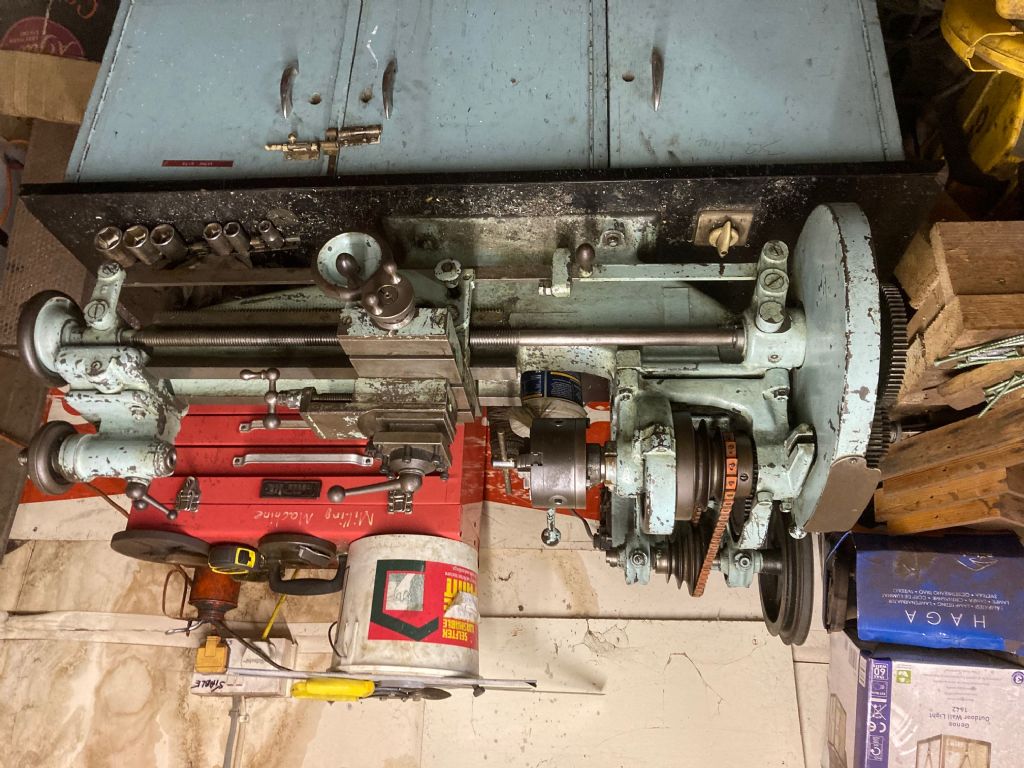
. I was thinking in terms of finding a similar type of 4-jaw chuck with integral thread of the correct size for the M so that I could use more of the gap to swing something oversize in rather than relying on a faceplate set-up, but I take the point about overhang on either the carriage or the tooling.

                                      I won't be running it until the bearing is fixed – I can't anyway as it currently only has one of the two drive belts in place. I'm not aware of there being any felt though – it appears to simply feed through the hole in the wedge directly on to the spindle bearing.

                                      The information about carbide inserts is particularly interesting – I am not very good at grinding up HSS and whilst I am sure I will improve, I will waste a lot of time and material (or do a lot of filing to restore surfaces) in the meantime, so inserts would make life considerably easier.

                                      Based on the suggested information it appears to be possible to take much heavier cuts than I was expecting which would be good news if true, although 0.1mm per pass is what I am used to so can live with it.

                                      Alec

                                      #603153
                                      David George 1
                                      Participant
                                        @davidgeorge1

                                        This is my lathe cutting stainless steel roughing out with a carbide indexable tool. The correct tool with right speed and feed taking about a 0.1 inch cut.


                                        David

                                        Edited By David George 1 on 26/06/2022 16:11:48

                                        #603307
                                        Howard Lewis
                                        Participant
                                          @howardlewis46836

                                          The M type is an old machine, probably designed before carbide tips were produced. the bearings would probably be damaged if it were run at the speeds and feeds that optimise carbide tips.

                                          For almost everything, except hardened materials, HSS will suffice. (That is where carbide comes into its own, with swarf coming off like red hot wire!. )

                                          Possibly, for very fine cuts, HSS is the better.

                                          Again, for most purposes, the exact clearance angle is not desperately critical. OK, the book may say 10 degrees, but probably you wouldn't notice if the clearance was actually 7 or 12 degrees.

                                          For the cost of one carbide tip, you can but a 1/4" HSS toolbit that can be reground to sharpen for the equivalent life of several carbide tips. And HSS does not chip as easily as carbide with interrupted cuts, of if you bang it!

                                          Probably, the ultimate in easily ground tools is a Tangential Turning Tool. You will meed a means of setting easily to centre height, but it only needs one face grinding, and you can buy the jig with the tool, or make one if you make your own. (At least two designs have been published in MEW for the home maker )

                                          There is many a good tune played on an old fiddle!

                                          Howard

                                          #603960
                                          Alec Gunner
                                          Participant
                                            @alecgunner39277

                                            Thanks Howard,

                                            It's my understanding that the main limitation with running the M at high speed is that it has plain bearings which will be damaged by doing so. High feeds should not cause a problem – this is pretty robust, so Dave Halford's comments on machining steel using tooling and settings designed for aluminium are very interesting, although having had a quick look aluminium-specific tooling certainly does not look cheap!

                                            I hadn't heard of the Tangential Turning Tool – that certainly looks like it would make my life easier. Filing the edges to 12deg and chasing out the groove for the cutter by hand would be an interesting challenge but as you say, absolute adherence to the angles probably isn't critical so I could get close enough for it to work.

                                            At present I am still waiting for my C-spanner to turn up (supposed rapid delivery time has not been met) so am a bit stuck but once I can get the headstock sorted out I should be able to get on and actually use it for something, which will be a lot more satisfying.

                                            Alec

                                            Edited By Alec Gunner on 02/07/2022 16:47:21

                                            #604068
                                            Howard Lewis
                                            Participant
                                              @howardlewis46836

                                              Tangential Turning Tools and general ramblings.

                                              If you can access earlier Issues of MEW, two designs for shop made Tangential Turning Tools have been published.

                                              The first design was to take 1/8" toolbits. (I made up a lookalike for 5/16" and it works like a dream. )

                                              Having a square shank, it involved milling at compound angles (Not impossible to file by hand, if you are careful ) And am not sure that all the angles are terribly critical

                                              The second version made life easier, in some respects, because it entailed milling the 12 degree angle onto the shank, to change it from square to trapezoidal.

                                              The jig for grinding to sharpen, is simple to make.

                                              The Eccentric Engineering version uses a 33 degree angle rather than the 30 degrees shown for the sharpening jig in the MEW articles.

                                              Once made, the advantage is (Apart from the fact that it performs well ) that there is only one face to grind.

                                              Compared to carbide tips, a HSS toolbit can better withstand the occasional knock, and in cost terms provides a lot more tool life for the cost of one carbide tip.

                                              You do need a Centre Height Gauge to set the tool easily. (Making one can be a useful learning experience for a beginner, and results in a tool which is always useful )

                                              Making such tools (Tailstock sliding Die and Tap holders can also be a good means of gaining experience, confidence and familiarity with the machine, while finishing up with tools that can be used for years to come.

                                              I cheated and bought the actual Die Holders, but made up the arbor and body for the tool.

                                              You can make the main body of the tool as simple, or as complicated as you like.)

                                              For the Tailstock sliding Tap holder, again I bought ER collets and had to screw cut the 1.5 mm pitch thread.

                                              (A more daunting task for a beginner, probably left until more experienced )

                                              Both these tools are particularly useful when producing fine threads, since the newly cut thread has minimal load imposed on it by pulling the tool along the arbor, rather than trying to [pull a tailstock along the lathe bed.

                                              (I found out that the hard way trying to cut a 40 tpi Model Engineer thread!

                                              But interrupted cuts will tend to hammer the toolbit down below centre height, so that it needs resetting.

                                              And, HSS is no match for hardened steel, where carbide will cut it easily, with interesting, brown, blue or even red hot swarf!

                                              Now, in addition to the ones for 1/8" toolbits, I use the Eccentric Engineering version, with the 1/4" toolbit for most of my turning work, especially for finishing.

                                              A feshly ground tool will remove 0.0005", or less, a side for finishing mild steel.

                                              HTH

                                              Howard

                                              #604074
                                              Nick Wheeler
                                              Participant
                                                @nickwheeler

                                                I'm about to make 2 left and one right of these from 10×20 steel and 1/8" bits:

                                                tangential tool holder v1.jpg

                                                #604095
                                                SillyOldDuffer
                                                Moderator
                                                  @sillyoldduffer

                                                  Posted by Alec Gunner on 26/06/2022 15:38:51:

                                                  The information about carbide inserts is particularly interesting – I am not very good at grinding up HSS and whilst I am sure I will improve, I will waste a lot of time and material (or do a lot of filing to restore surfaces) in the meantime, so inserts would make life considerably easier.

                                                  Based on the suggested information it appears to be possible to take much heavier cuts than I was expecting which would be good news if true, although 0.1mm per pass is what I am used to so can live with it.

                                                  Alec

                                                  I prefer inserts to HSS for exactly the reasons Alec gives: they potentially eliminate the need to buy a grinder and learn how to use it. Not everyone is good at grinding, so beware folk to whom it came naturally: they insist it's easy and just needs a bit of practice. Yeah right, so does learning Integral Calculus…

                                                  In practice I use both, 80% inserts, switching mainly to HSS when an unusual tool profile or very fine cuts are needed, or I'm having trouble getting a good finish.

                                                  Carbide is fussier than HSS about depth-of-cut, feed-rate and RPM. Works best when pushed hard at high-speed, removing metal 3 to 12 times faster than HSS. Though sharp Carbide inserts work well enough for most purposes, hobby lathes don't have the power, speed or rigidity needed to get industrial performance out of them.  I still prefer inserts!

                                                  Assuming the drive-train and cutter are both in good order and the gibs are adjusted, depth of cut depends mostly on the power of the motor and the material. Rule of thumb, 1HP will remove 1 cubic inch of mild-steel per minute.

                                                  I suppose maximising depth of cut might be useful when roughing out, but even though my lathe can do it I rarely take cuts more than 2mm deep (4mm off the diameter). Though there are exceptions, I find it more civilised to take cuts between 1 and 0.1mm deep, less for finishing.

                                                  Best thing to do is experiment. Get some free-cutting mild-steel bar, at least 25mm diameter. Set RPM to 10000/25 = 400 (this is about right for HSS, triple RPM for carbide if the machine can run that fast), and try taking various depths of cut over a 30mm length with a sharp tool, with minimum overhang in the tool-post.

                                                  Listen and observe. The machine should sound as if it's definitely working hard but not in distress. Nothing should be bending, lifting, twisting, or otherwise misbehaving mechanically.  Look for the best compromise between quick metal removal, controlled accuracy and good finish.

                                                  Once depth-of-cut is understood, experiment with feed-rate in the same way.

                                                  Friendly materials cut well over a wide range and are very forgiving. Difficult materials are much fussier about using the right shaped tool and getting all three parameter spot on. Some are impossible.

                                                  If you're a man in a hurry, beware of fitting a giant motor to remove metal extra-fast: the drive train will wear rapidly, and accuracy goes to pot when the frame is twisted by excessive torque. Damage done by a crash is much worse too!

                                                  By the way, don't expect to file HSS – it's too hard! Grinding is the answer.

                                                  Dave

                                                  Edited By SillyOldDuffer on 03/07/2022 13:41:51

                                                  #604166
                                                  Hopper
                                                  Participant
                                                    @hopper
                                                    Posted by SillyOldDuffer on 03/07/2022 13:34:26:


                                                    I prefer inserts to HSS for exactly the reasons Alec gives: they potentially eliminate the need to buy a grinder and learn how to use it. Not everyone is good at grinding, so beware folk to whom it came naturally: they insist it's easy and just needs a bit of practice. Yeah right, so does learning Integral Calculus…

                                                    When I was in high-school, every 15-year-old boy could grind a lathe tool bit, sharpen a drill bit and a plane blade. Was part of the metalwork/woodwork class that all boys took. I don't remember any boy who could not master all three skills in fairly short time.

                                                    It;s not rocket science, or even integral calculus.


                                                    Edited By Hopper on 04/07/2022 00:06:09

                                                    #604176
                                                    Jon Lawes
                                                    Participant
                                                      @jonlawes51698
                                                      Posted by Hopper on 03/07/2022 23:55:28:

                                                      Posted by SillyOldDuffer on 03/07/2022 13:34:26:

                                                      I prefer inserts to HSS for exactly the reasons Alec gives: they potentially eliminate the need to buy a grinder and learn how to use it. Not everyone is good at grinding, so beware folk to whom it came naturally: they insist it's easy and just needs a bit of practice. Yeah right, so does learning Integral Calculus…

                                                      When I was in high-school, every 15-year-old boy could grind a lathe tool bit, sharpen a drill bit and a plane blade. Was part of the metalwork/woodwork class that all boys took. I don't remember any boy who could not master all three skills in fairly short time.

                                                      It;s not rocket science, or even integral calculus.

                                                      Edited By Hopper on 04/07/2022 00:06:09

                                                      I can sharpen HSS, but find carbide suits most things I need to do. As mentioned, it's useful for unusual shapes or form tools, but for the most part my pile of HSS cutting tools is gathering dust.

                                                      I'm sure most people could operate a treadle lathe rather than an electric motor, but who wants to do that if there is a better option?

                                                    Viewing 25 posts - 1 through 25 (of 31 total)
                                                    • Please log in to reply to this topic. Registering is free and easy using the links on the menu at the top of this page.

                                                    Advert

                                                    Latest Replies

                                                    Viewing 25 topics - 1 through 25 (of 25 total)
                                                    Viewing 25 topics - 1 through 25 (of 25 total)

                                                    View full reply list.

                                                    Advert

                                                    Newsletter Sign-up