Sieg SX3 and Machine-DRO 3-Axis Kit

Advert

Sieg SX3 and Machine-DRO 3-Axis Kit

Home Forums Workshop Tools and Tooling Sieg SX3 and Machine-DRO 3-Axis Kit

Viewing 25 posts - 1 through 25 (of 28 total)
  • Author
    Posts
  • #463587
    Mike Donnerstag
    Participant
      @mikedonnerstag

      I have a Sieg SX3 milling machine and have just purchased a 3-axis DRO kit from Machine-DRO. Does anyone have experience of fitting this kit to the SX3? I have laid out all the parts of the kit on my workbench and more I'm a little befuzzled (technical term).

      I noticed a page on the internet where someone had mounted the Z-axis scale on the inside of the column, though I couldn't find any detailed photos. Has anyone else done this?

      The readout came with just a solid horizontal mounting bar and two relatively big (I think M8) bolts. I'm not sure what to mount this to, as the SX3 column 'cover' is just fabricated from relatively thin sheet steel. How have people mounted the DRO display to the machine?

      Please help! I don't want to drill and tap holes in the wrong place!!

      Many thanks,

      Mike

      Advert
      #19696
      Mike Donnerstag
      Participant
        @mikedonnerstag
        #463590
        Steviegtr
        Participant
          @steviegtr

          Have you had a look on youtube. Lots of dro conversions on there. If not your model at least get some idea's.

          Steve.

          #463609
          Steviegtr
          Participant
            @steviegtr

            Try this one. It is a Grizzly G0704 but similar points of fixing.

            **LINK**

            Steve.

            #463619
            Martin Mcgiff
            Participant
              @martinmcgiff65046

              I've just fitted one last week as im now onto the cross slide.

              You need to move the black controller back section out 30mm to allow for the scale to fit inside, also if you clip off 10mm each side of the black controller then the head can lift 60mm higher (bonus )

              I will sort some pictures later today

              Martin

              #463620
              Ron Laden
              Participant
                @ronladen17547

                Google fitting DRO to sx3 and you will find quite a lot of info.

                #463622
                JasonB
                Moderator
                  @jasonb

                  On my fairly similar X3 I fixed the bottom bracket to the base of the column, make sure you raise the end of the scale enough so the Y one can pass under it. These are M-DRO scales and covers.

                  Then at the other end fixed down into the top of the column using one of the existing cover screws

                  Will take a photo of how the read head is fixed to the mill's head later but yours may need a slightly different fixing due to the swivel head.

                  Have you got  alink for the SX3 kit as I can't see one listed on their site.


                  Edited By JasonB on 10/04/2020 07:49:08

                  #463627
                  Mike Donnerstag
                  Participant
                    @mikedonnerstag

                    Thanks chaps. I think I'll fit the X and Y axes first, as they are more straightforward. I have several more questions, which I should probably call Machine-DRO about, though I'd like to get the DRO fitted over the Easter weekend, hence why I'm asking here. I also intend to do more research on the internet to see if I can find answers to these questions, though if anyone knows, it could save me a lot of time and I would be very grateful.

                    Q: On each magnetic scale is printed "INC 2mm –>" Any idea what this means?

                    Q: Has anyone fitted the Z axis INSIDE the column? It seems like an elegant way to conceal the scale, though I'm not sure whether there would be any dificulties.

                    Q: The M-DRO 'Encoder Install Guide' says nothing about actually cutting the scales to length, apart from how to measure. Any tips here?

                    Q: The package came with many powder-coated brackets that aren't in the photograph on the website. Are these additional brackets for the Z axis?

                    Q: How have people attached the display to the machine. I notice on the Axminster version that the arm is fitted to a long rod or bolt, not included in the kit. Again, if anyone has photos I would be very grateful.

                    Once again, many thanks,

                    Mike

                    #463664
                    Mike Donnerstag
                    Participant
                      @mikedonnerstag

                      JasonB: Many thanks for your photos. The kit I was recommended by Machine-DRO to buy is a universal mounting kit with magnetic scales. I went for the 3 axis kit with the LCD DRO:

                      https://www.machine-dro.co.uk/easson-lcd-3-axis-dro-package-5955

                      Thanks,

                      Mike

                      #464406
                      Mike Donnerstag
                      Participant
                        @mikedonnerstag

                        The 'Universal Fitting Kit' is proving to be universally frustrating! Has anyone used the fitting kit or has everyone made up their own brackets for fitting the DRO scales and head? If anyone has actually used the fitting kit, would you be able to post some photos?

                        Edited By Mike Donnerstag on 13/04/2020 15:19:33

                        #464409
                        Martin Mcgiff
                        Participant
                          @martinmcgiff65046

                          93640383_3159703014049492_8846117099009998848_n.jpg

                          I made my own as was a better instalation as i also fitted the z axis in the column and moved the controller box back 30mm 92844905_532307884138885_3790375047504330752_n (1).jpg

                          Edited By Martin Mcgiff on 13/04/2020 15:40:23

                          #464410
                          Mike Donnerstag
                          Participant
                            @mikedonnerstag

                            Hi Martin – many thanks for the photos. By 'controller box' do you mean the display? Do you have any other photos? Are these the optical encoders?

                            #464412
                            Martin Mcgiff
                            Participant
                              @martinmcgiff65046

                              The machine controller i mean is the big black box on the back of the machine, i moved it by 30mm to allow the scale to be fitted inside, i also modified it to allow the head to travel 50mm higher, i fitted the DRO arm to the top of the controller box on the right hand side, it is ok and at the right height to read it.

                              i have painted the floor today but will get some pictures tomorrow

                              Regards

                              Martin

                              #464413
                              Mike Donnerstag
                              Participant
                                @mikedonnerstag

                                That's great – many thanks. It sounds as if you've done some interesting modifications. Looking forward to the photos.

                                Cheers,

                                Mike

                                #464416
                                Ron Laden
                                Participant
                                  @ronladen17547

                                  Hi Mike,

                                  I cant speak for the SX3 but I fitted my Sieg SX2P mill with a 3 axis set (from ARC) and they came with a variety of brackets and fixings, some of which I modified and used but also made some of my own. I think that is the norm when you get a universal kit, probably different when you have a set made for a specific make and model of machine.

                                  Unless you can find someone or a write up that covers the detail and parts used in fitting a DRO set to the SX3 you may find that you are on your own. Actually its not that difficult to fit a set just takes a bit of sizing up, positioning and either using the supplied fittings or modifying them and/or making your own.

                                  Ron

                                  Edited By Ron Laden on 13/04/2020 16:18:20

                                  P.S. There you go Martin will probably have all the info you need. 

                                  Edited By Ron Laden on 13/04/2020 16:19:40

                                  Edited By Ron Laden on 13/04/2020 16:20:12

                                  #464441
                                  Mike Donnerstag
                                  Participant
                                    @mikedonnerstag

                                    Hi Ron,

                                    Thanks for that information. I think I'm coming to the same conclusion – the 'fit-everything' kit actually fits nothing well, and needs extensive modification to achieve a usable result, albeit ugly. For a much neater result, it seems that making all of the brackets from scratch is the only way, and probably the way I'll go for each axis.

                                    Mike

                                    #464575
                                    Martin Mcgiff
                                    Participant
                                      @martinmcgiff65046

                                      Just on second coat of the garage floor but some quick pictures this morning of position ot the DRO arm, inside the rear column 2 cross beams and a bracket (all inside the black control panel) i moved back the screws on top 30mm to allow for this and i also removed 10mm each side at the top to allow the head to rise 50mm higher !!! 93234291_3733922976680341_2806761531662925824_n.jpgArm top right

                                      93156038_248617186182769_6193841499419967488_n.jpgtop of head screws moved 30mm back93001908_237492550789166_2834978938516668416_n.jpgTo allow Z scale inside 93566013_504843610395967_2313160959176212480_n.jpg93430323_851834245328550_5032960308017102848_n.jpg93303573_2734102963476369_4176346952188821504_n.jpg

                                      #464630
                                      Mike Donnerstag
                                      Participant
                                        @mikedonnerstag

                                        Interesting! Many thanks Martin.

                                        #464836
                                        Martin Mcgiff
                                        Participant
                                          @martinmcgiff65046

                                          I have Moved the milling machine back into its final position, picture showing the DRO arm position92722314_2444467582531052_937057629425893376_n.jpg

                                          #467401
                                          Mike Donnerstag
                                          Participant
                                            @mikedonnerstag

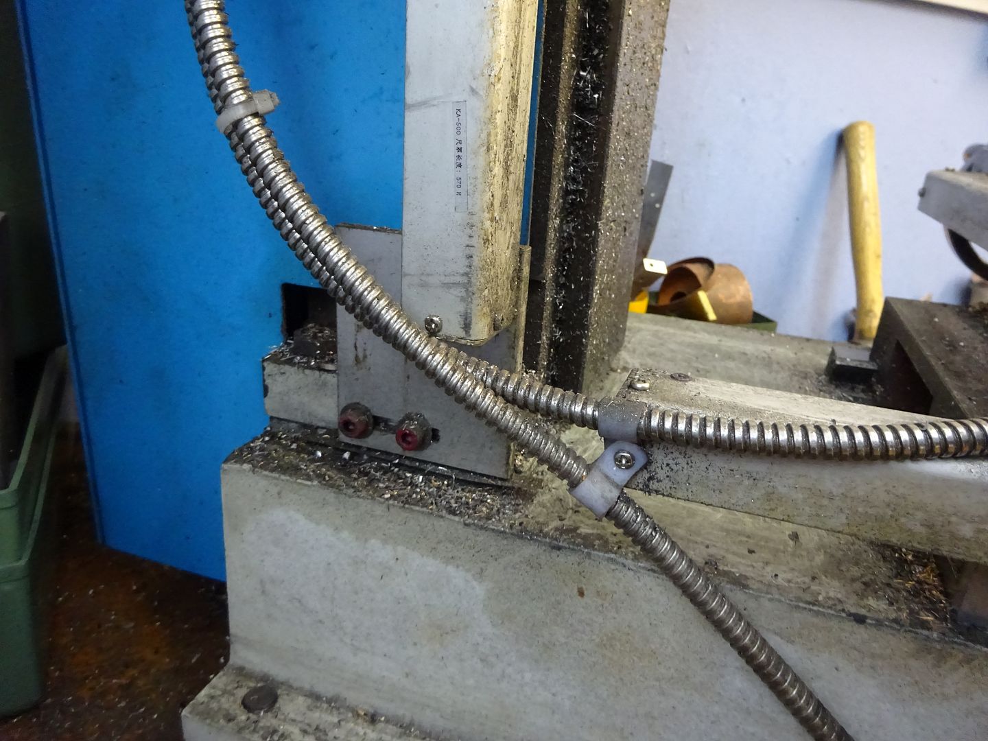
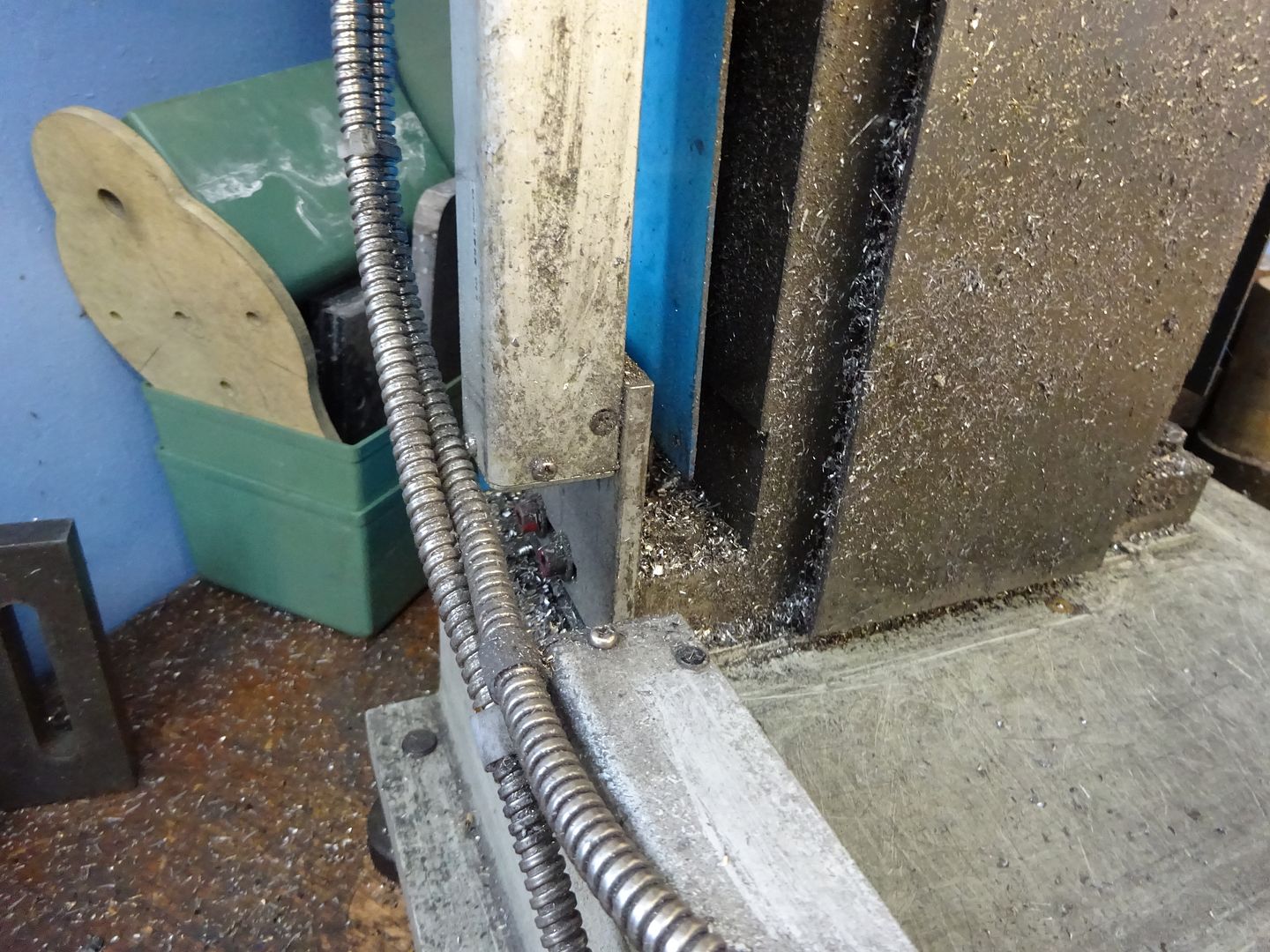
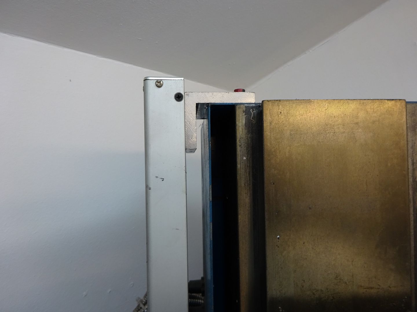
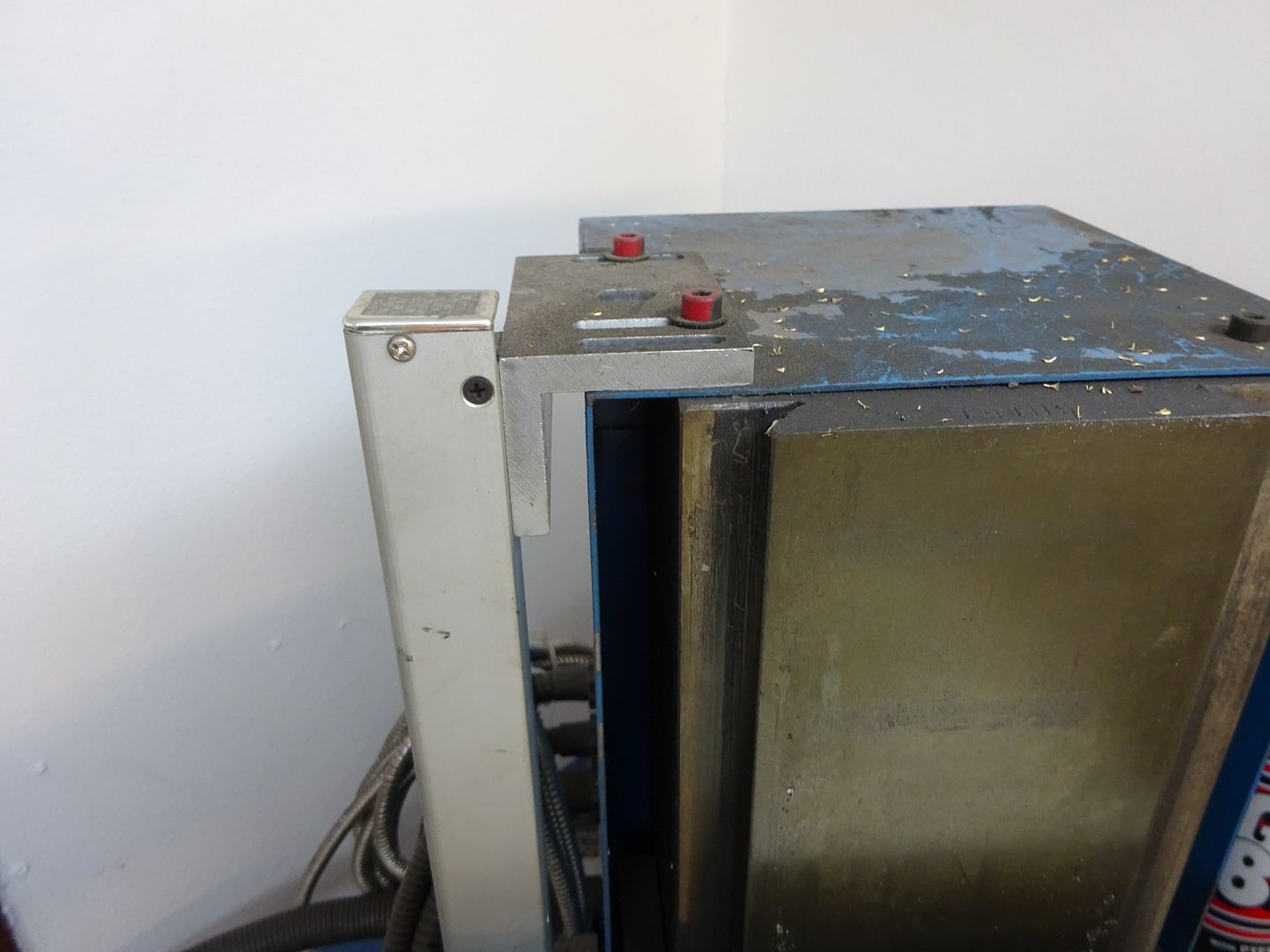
                                            Many thanks to everyone who commented on this post. I decided to install the Z-axis inside the column, as far back as possible to ensure the cable does not foul the Z-axis leadscrew. Photos follow:

                                            complete installation.jpg

                                            dro display.jpg

                                            x-axis.jpg

                                            y-axis.jpg

                                            z-axis at bottom of travel.jpg

                                            z-axis at top of travel.jpg

                                            z-axis cable.jpg

                                            I'd be very interested if anyone has any comments.

                                            Mike

                                            #544129
                                            James Hall 3
                                            Participant
                                              @jameshall3

                                              I'm impressed by the neatness of your installation, particularly with the mounting in the rear column.

                                              I've just invested in a 3-axis kit for my SX3 from MachineDRO so would like to pick your brains and benefit from your experience if you don't mind. It will be a while before I actually find time for my installation but I'd like to get it clear in my mind how I will go about it. It may be that I should address some questions to MDRO, and that the answers to some will or would be obvious when the rear column cover is removed – but in a restricted space my mill takes a lot of moving so a quick look inside beforehand is not so easy.

                                              An easy starter – you obviously discovered how to cut the magnetic strips to length, please tell.

                                              Is the mounting for the display fixed to the pressed-steel cover, or through it to something more substantial?

                                              On the X-axis you have mounted the scale on the table with the read head fixed, but vice-versa for the Y-axis – with the scale fixed and the head travelling with the saddle. Why have you chosen to do thi?

                                              I'll leave the rest, rather than over-burden you with the whole lot in one installment.

                                              Thanks.

                                              #544134
                                              Martyn Edwards 2
                                              Participant
                                                @martynedwards2

                                                Same kit but slightly different approach on the Y and Z Axis.

                                                d976e474-88f9-4784-8803-ed6b3d708a53.jpeg

                                                cda84fff-d193-44f7-a7ff-0334bca5ae51.jpeg

                                                529911ce-e503-42a5-8635-b408d41fca8f.jpeg

                                                48769688-1aa3-4b72-a79b-ef0d75bd3301.jpeg

                                                2c223bc7-b4ed-48a3-ad49-502ded34131b.jpeg

                                                #544707
                                                James Hall 3
                                                Participant
                                                  @jameshall3

                                                  Thanks Martyn – interesting photos and another good looking installation. See that you have gone for fixed Y-axis read head and scale on saddle, but wondered what Mike Donnerstag's reasoning was behind doing it the other way round.

                                                  How did you cut the magnetic strip to length?

                                                  I still like the neatness of hiding the Z-axis gubbins in the column, but am hoping to pick Mike's brains on that.

                                                  #544709
                                                  JasonB
                                                  Moderator
                                                    @jasonb

                                                    If you get a longet scale extrusion for the Z then you can just mount that at either end and no need for the extra backing plate shown in Martyn's photo. I'd also fit the bracket to the casting rather than the sheet metal cover, you can make use of the existing screw hole in the top of the column.

                                                    #544764
                                                    Mike Donnerstag
                                                    Participant
                                                      @mikedonnerstag

                                                      Apologies for the delayed reply.

                                                      In response to James' questions:

                                                      The magnetic strips are easily cut to length. I think I just used tin snips. The aluminium extrusions obviously need to be cut with a hacksaw.

                                                      The mounting for the display is fixed to a thick aluminium plate behind the pressed-steel cover. This reinforces the mounting substantially.

                                                      Regarding my thinking behind how I mounted the scales and readers, it was all about future-proofing. Specifically, my objectives were:

                                                      1) To leave each of the three scales as long as possible to potentially mount them to a different machine in the future

                                                      2) To ensure the ends of the table are completely clear of mounting brackets, etc., to allow a power feed or even CNC motors to be mounted in the future.

                                                      I think this answers your questions so far.

                                                      I am still not too happy with my Z-axis readings. I think this is due to the 'spring' in the machine between the movement of the leadscrew nut and the head movement. I haven't investigated whether this is the gib adjustment, which may be a little tight, or whether it is fundamentally the fact that the reader is some way from the head. The travel of the feedscrew nut, to which the reader is fixed, doesn't perfectly follow the height (Z-position) of the head. The movement also seems to be too juddery to rely on for accurate height settings, hence why I use the quill for accurate height settings.

                                                      Jason: I'd be very interested in your thoughts on this. Specifically, would you expect to be able to set the head height just as accurately as the quill? Also, do you have any hints on how best to set the head gib so that it's not too tight or too loose? (Perhaps this is one for Ketan?)

                                                      Cheers,

                                                      Mike

                                                    Viewing 25 posts - 1 through 25 (of 28 total)
                                                    • Please log in to reply to this topic. Registering is free and easy using the links on the menu at the top of this page.

                                                    Advert

                                                    Latest Replies

                                                    Viewing 25 topics - 1 through 25 (of 25 total)
                                                    Viewing 25 topics - 1 through 25 (of 25 total)

                                                    View full reply list.

                                                    Advert

                                                    Newsletter Sign-up