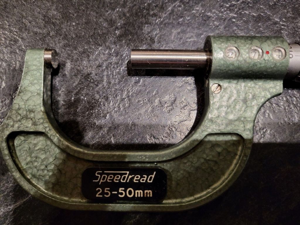
GKN ‘Speedread’ micrometer

Advert

GKN ‘Speedread’ micrometer

Home Forums Workshop Tools and Tooling GKN ‘Speedread’ micrometer

Viewing 7 posts - 1 through 7 (of 7 total)
  • Author
    Posts
  • #104381
    Siddley
    Participant
      @siddley

      Does anyone know anything about these mechanicaldigital mikes ? I've got an imperial 0-1" version and I'd love to find it a metric friend.

      It's no more or less accurate than any of my other mikes, but I just think the mechanism is very cool ( and easy to read of course )

      Advert
      #16938
      Siddley
      Participant
        @siddley
        #657503
        peak4
        Participant
          @peak4

          To rejuvenate a very old thread, does anyone have a manual, or a knowledge of how to re-set/calibrate these mics please.
          I've got a pair of imperial and metric 0-1" & 0-25mm already, which are fine, but just picked up a 25-50mm where the number readings are well off.

          I also have an older 0-1" Slocomb version of the same, which was made according to the original Davenport Patent of 1916, which I've downloaded, so I assume the GKN Shardlow is similar.
          https://worldwide.espacenet.com/patent/search/family/003277953/publication/US1210051A?q=US1210051A

          GKN Shardlow Speedread 25-50mm - 2.jpg

          Bill

          #657675
          peak4
          Participant
            @peak4

            For completeness in case anyone searches for this in the future.

            A Few Notes on Re-indexing a GKN-Shardlow 25-50mm Speedread Micrometer.

            N.B. is isn’t an official procedure, and very much trial an error, with lots of the latter.

            Please read in conjunction with the US patent for a micrometer from 1956 by Davenport.
            **LINK**

            A recent purchase of a good used example of this micrometer arrived with the direct reading numeric display out of sync with both the spindle and adjacent digits.

            I believe Screw No.60 on the original patent diagram vibrated loose whilst the parcel was in the post
            This led to an eccentric spindle, Part No.52 moving and allowing the small gear No.46 to disengage.
            Unfortunately, unlike the original from 1916, this spindle is made of plastic, and also seems to have an eccentric pivot allowing an adjustment of the gears’ engagement.
            Screw No 60 is the one just below and to the left of the first digit display window.

            Disassembly (partial)

            First I needed to partially disassemble the instrument, but fortunately I didn’t need to dismantle the gearbox or display itself.

            The thimble is held on a taper at the end of the main spindle No.14 but just removing the end screw only releases the knurled adjusting collar.
            N.B don’t lose the ratchet spring, and note it’s orientation before removing.

            I’ve no idea how you are supposed to release the thimble from the taper without a special tool, but this worked for me; unscrew the thimble as far as it will go and wind it back in very slightly to avoid straining anything.
            This exposed the collar used to compensate for thread wear, nut note that’s it’s the plain black ring with the C spanner hole, rather than the nut No.10 on which it’s mounted. I used the end of a 12” steel ruler in the gap as a lever, and the thimble pinged off without too much effort, though a mini hot air gun might help if it’s tight.

            Wind the main spindle half in towards the 25mm end, and remove the nut No10, complete with the thread wear compensation ring; I loosened the ring as well so I had a better feel for what was happening. You might need to adjust the spindle in one direction or the other as the nut comes out of the main bore.
            The main spindle No.14 will slide out complete with nut No10 Put the nut to one side, but note that the outer thread on it appears to be coarser than the one on the main spindle.
            I think that the spindle thread might be multi-start, as when you screw the nut back in later, the spindle moves outwards.

            Note the collar No34 on the spindle No.44 with the lug No. 30 and look down the bore for the groove in tube which it engages to turn the gearbox/display.

            I now re-inserted the spindle, which is a sliding fit and used that to turn the inner tube/sleeve to line up the numbers on the display wheels. Gently tightening screw No60, in conjunction with rotating the plastic grub screw, locked the eccentric spindle No 52, and allowed a smooth drive to the display wheels. (The plastic screw is effectively No 54 on the patent, but slightly different in this production version)

            Re-assembly to follow in the next post
            Bill

            #657676
            peak4
            Participant
              @peak4

              Reassembly

              Much trial and error here, in order to get the indexing correct for workpiece length.
              For this particular instrument, as you screw nut No10 into the bore, the spindle moved outwards, rather than in, presumably there is a double start thread involved, but it has the overall effect of a differential screw.

              I selected a 35mm gauge block and slid the main spindle down the bore to contact it (I didn’t have one, so used a 25mm block on end; it doesn’t need to be exact, but should be close to a known measurement to allow for the differential screw compensation).
              Since the spindle moves outwards, as you screw in nut No10, I pre-set the display to 55mm.
              Run nut No10 down the spindle No14, but make sure the spindle doesn’t rotate, as we don’t want to alter the display from 55.0mm.

              As nut No10 engages in the internal thread of the bore, the spindle will start to withdraw away from the block, so keep an eye on the engagement and re-adjust accordingly; as soon as the outer thread becomes engaged by a couple of turns, you can dispense with the block for now.

              Don’t screw nut No10 fully home, though it will tighten slightly as it gets closer; I left about a 1mm gap; readjust the wear compensation sleeve ring to allow a smooth movement.
              Now use the 25mm block the correct way around and advance the spindle as though you are measuring it.
              It’s unlikely to read 25mm straight away, but the differential screw effect of turning nut No10 allows for fine adjustment.

              I then tried several other measurements up to a 50mm block and had good repeatability.

              Slide on the thimble, don’t forget the ratchet spring, with the micrometer still measuring a block, and replace the end screw, align a suitable mark, gently nip up the taper, only lightly finger tight.
              I very carefully slid the block out of the way, held the thimble in some curved jaw, rubber coated pliers, and then fully tightened the end screw. I didn’t want to strain anything whilst the micrometer was still measuring a block.

              I then re-measured several blocks and slightly adjusted the outer engraved sleeve to align with a mark on the thimble in the conventional manner.

              I’m getting repeatability all the way, with a variety of blocks, through the range from 25-50mm to within 0.01mm, so quite happy with the final result.

              There is a copy of the diagram (only) from the US patent in the same album as the photo from my earlier post on this thread.
              I've just included it for ease of reading the above notes.

              Bill

              Edited By peak4 on 23/08/2023 19:28:33

              #657746
              Rolster
              Participant
                @rolster

                Bill many thanks for the detailed explanation and link to the drawing.

                I have an one inch imperial version back at home which has a very stiff spindle and needs to be overhauled, but without the drawing it looked a bit dicey, so now forearmed with your research and drawing, i'll give it a go.

                I am not sure how the spindle got so stiff but as it was second hand when i bought it in the last century and came in a belt pouch so probably was sat on at some stage.

                BR Roland

                #657747
                peak4
                Participant
                  @peak4
                  Posted by Rolster on 24/08/2023 12:13:26:

                  Bill many thanks for the detailed explanation and link to the drawing.

                  BR Roland

                  Bear in mind that the drawing relates to the original patent from 1916 (not 1956 as per my typo) and the production models of the GKN-Shardlow do differ.

                  Both my 1" & 25mm ones, which came in the leather cases, were stiff when they arrived here off eBay.

                  I didn't need to risk dismantling them, and I'd avoid it if possible, particularly as the tiny spindle in the gearbox is made of plastic.
                  I'd try and keep any lubricant away from there, but the main spindle thread can be oiled as normal.
                  Unwind the thimble almost as far as it will go, I don't think it will come all the way out without removing Nut No10, but do be careful; this should expose the adjustment collar.

                  edit- just checked my 1" version, and unwinding the thimble doesn't expose the adjusting collar in the way it did on my 25-50mm, so it looks like you need to remove the thimble from its taper to alter the backlash; I must have just added a couple of drips of oil down the gap without removing the thimble.
                  The exposed nut is Nut No10, not the backlash adjustment, so don't remove that unless you need to

                  As regards oil, I've taken to using Balistol Universal oil as an instrument lubricant. It's strange stuff with an odd aroma, and originates from Germany; I have ½ litre bottles as well as a spray can.
                  https://ballistol.co.uk/products/ballistol-universal-oil?variant=39852136366262
                  It claims to be OK with metal, wood, leather and plastic, so you can even use it for cleaning wooden micrometer boxes and leather cases.
                  I'd try and keep it away from the display end though in case it mists the windows, or strips the paint off the dials.

                  I did pick up a Borlotti direct reading micrometer a while ago, but by the time it arrived here, the vibration in transport meant that most of the paint had vibrated off the plastic wheels, so whilst they turned and counted OK, the display didn't show many numbers.

                  Bill

                  Edited By peak4 on 24/08/2023 12:44:22

                Viewing 7 posts - 1 through 7 (of 7 total)
                • Please log in to reply to this topic. Registering is free and easy using the links on the menu at the top of this page.

                Advert

                Latest Replies

                Viewing 25 topics - 1 through 25 (of 25 total)
                Viewing 25 topics - 1 through 25 (of 25 total)

                View full reply list.

                Advert

                Newsletter Sign-up