Homemade IIndexing Attachment- Assistance needed

Advert

Homemade IIndexing Attachment- Assistance needed

Home Forums Workshop Tools and Tooling Homemade IIndexing Attachment- Assistance needed

Viewing 10 posts - 1 through 10 (of 10 total)
  • Author
    Posts
  • #99728
    Johan Crous
    Participant
      @johancrous15881

      I am now drawing a proposed Indexing tool for my mini mill, based on the Harold Hall Design, but I will make use of what I have available in my garage:

      [IMG]http://i798.photobucket.com/albums/yy261/Boerseun1/Workshop/IndexIdea.jpg[/IMG]


      It will be a direct indexing one with five sets of holes in one plate, 90, 80, 72, 60 and 48.
      The main body will be of aluminum. the base plate of bright mild steel, as well as the spindle.
      The indexing plate will be of brass (75mm) and there will be 80mm chuck added.
      The green handle will be the spindle lock – forcing a brass pad against the spindle (I am still learning the CAD program so please excuse the bad design).
      The plunger will have to penetrate the indexing plate from the left (back) of the picture because there is not enough space to penetrate from the right to the left. The innermost set of holes will be well between the plate and the main body. The operator must turn the spindle by grabbing the Index plate as a handle after the lock has been disengaged.

      The spindle is now bored through 8mm, and I will see if I will add a MT 1 hollow.

      My question is to find a simple plunger design that will work with this design. I don't mind to make use of a screw-in type of plunger. This will most probably more sturdy than the type that is spring loaded (and easier to make). Ideas or links/references to other plunger designs will be very much appreciated.

      Edited By Johan Crous on 30/09/2012 12:10:04

      Edited By Johan Crous on 30/09/2012 12:11:24

      Edited By Johan Crous on 30/09/2012 12:18:01

      Advert
      #16903
      Johan Crous
      Participant
        @johancrous15881
        #99731
        Clive Hartland
        Participant
          @clivehartland94829

          Johan, I cannot get your Photo Bucket link to work? can you not do a direct link ?

          Clive

          #99732
          Terryd
          Participant
            @terryd72465

            Hi Clive,

            Here is the image, I copied the url between the square brackets at both ends i.e. miss out the [IMG] and [/IMG] when trying to open the link.

            I hope that Johan does not object to me doing this, if so I apologise.

            Best regards

            Terry

            #99739
            Clive Hartland
            Participant
              @clivehartland94829

              Thanks Terry, all clear now.

              Clive

              #99743
              Jeff Dayman
              Participant
                @jeffdayman43397

                Hi Johan,

                Have a look at http://www.mcmaster.com and search part 8498a551.

                Even if this is not the exact type of plunger you want, McMaster has just about every other kind there is, so you can probably find one. Good luck.

                JD

                #99744
                NJH
                Participant
                  @njh

                  Hi Johan

                  I made a direct dividing attachment some years ago to cut some clock wheels – see my photos album

                  I have shown the plunger of the type I assume you mean.

                  here is an exploded view;-

                  plunger components.jpg

                  The division plate I purchased ( from Chronos? maybe – I forget)

                  Most of the rest came from the scrap box and the major casting from a skip – one of those things you see and think "That might be useful one day"  – and this time it was! The barrel was from a scrap tailstock and, usefully, had a No 2 MT in the nose.

                  It all worked well, cost next to nothing and was made in a short time!

                  Here are some of the wheels cut on it.

                  clock wheels.jpg


                  If you want further details of the plunger send me a PM and I will do a sketch

                  Regards

                  Norman

                  Edited By NJH on 30/09/2012 15:45:23

                  Edited By NJH on 30/09/2012 15:46:46

                  #99747
                  Sub Mandrel
                  Participant
                    @submandrel

                    Hi Johan,

                    I made a similar dividing attachment for my mini lathe. I used a detent which can fit either between two teeth.

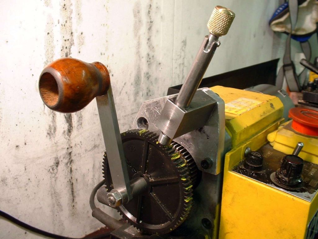
                    Obviously you need pin type plunger, but perhaps you could make use of my sprung design which includes a simple way to keep the plunger retracted by pulling it and twisting it .

                    For my small divising head, which uses a plate, I made a pin with a knurled cup fitted to it, this screws onto a hollow tube and the pin enmerges from the end into the dividing plate. Much slower.

                    Neil

                    You could use a spurung arrangement like this – the spring doesn't need to be hugely strong

                    detail of detent holder.jpg

                    The two slots are for the different plunger positions (i.e. at 90 degrees to each other) if the pin is turned right around, it stays retracted.

                    top end of plunger.jpg

                    fitted to lathe close.jpg

                    Edited By Stub Mandrel on 30/09/2012 16:25:44

                    #99757
                    Clive Hartland
                    Participant
                      @clivehartland94829

                      You have space at the bottom of the block and base, make a square block and drill right through it for a spindle.

                      Fit this parallel to the main spindle. Make a spindle to fit the hole in the block.

                      Cut a groove in the spindle so it has no sideways movement. Use a screw to fit the groove to hold it in its position, free to rotate but no left or right movement.

                      Make an arm that will fit over the main spindle and fix to the spindle in the lower block, cut a suitable slot along the center of the arm to carry your plunger mechanism.

                      The plunger mechanism like Neils or Normans will do and so it slides along the slot and can be locked in place with a knurled nut.

                      The hole in the arm will keep it lined up and stable in use.

                      Clive

                      #99760
                      Harold Hall 1
                      Participant
                        @haroldhall1

                        Photo 6 on this page Johan may be of help. See here

                        For anyone interested, the full version of this dividing head can be seen here

                        Harold

                        Edited By Harold Hall 1 on 30/09/2012 18:49:41

                      Viewing 10 posts - 1 through 10 (of 10 total)
                      • Please log in to reply to this topic. Registering is free and easy using the links on the menu at the top of this page.

                      Advert

                      Latest Replies

                      Viewing 25 topics - 1 through 25 (of 25 total)
                      Viewing 25 topics - 1 through 25 (of 25 total)

                      View full reply list.

                      Advert

                      Newsletter Sign-up