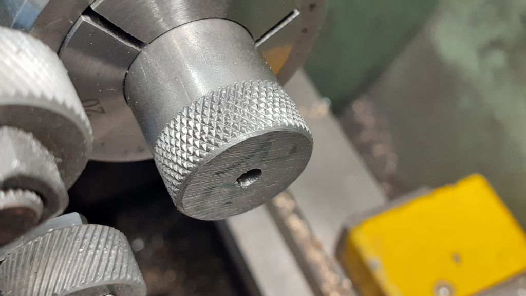
I have getting used to my new lathe by making a saw arbor for a 0.3mm blade and as far as I am concerned it turned out okay, but now I am making a spring loaded tap follower but the knurling has turned out rubbish, I have a knurling tool clamp type with a screwed knurled nut any suggestions please.
Thats a double or triple pattern with only one knurl doing any work.
Things to check :-
Is the material suitable? Anything that has work hardening tendencies will be hard to knurl at home. In general stainless steels can only be reliably and satisfactorily knurled using the cut knurling system.
Are the knurls sharp?
Do the knurls spin freely under load?
Is your knurling tool strong enough to apply enough force to the job and rigid enough to keep the knurls correctly aligned?
Is your knurling tool set up properly to pinch on the centre line of the job with the knurls aligned with the lathe axis?
The sample looks as if the knurls are out of line with the lathe axis and the tool is sufficiently flexible to let the ineffective knurl skid sideways.
Knurling using conventional push knurls is pretty brutal process. Considerable force and rigid tooling is needed if things are to just work. I have a hefty Marlco clamp knurler and ex-industrial machines. Even then the process is not always routine. It's very important tha the forces between the knurls are balanced. If I have issues its generally because I've gotten rush headed and not set things up balanced.
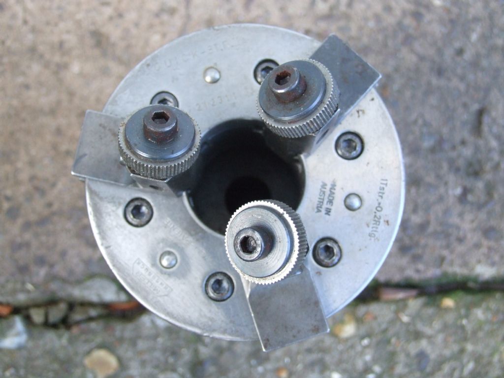
Although plenty of people have gotten good results from clamp and even push knurling on smaller machines my view is that the three wheel, hand squeezed "nutcracker" type is far more reliable on smaller lathes. Being hand operated you can feel whats going on. Its obvious when things aren't going well.
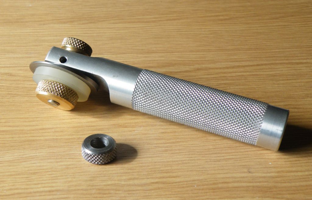
Here is picture of mine.
Bought when I was driving SouthBend 9" it instantly solved my knurling woes. The 9" Southbend is sturdy enough to make a decent stab at clamp knurling with a lighter weight tool or even push knurling but it always took a bit of experimenting to get good results. Even then there were failures where the job just point blank refused.
It's noticeable that people who report good results with clamp knurling on smaller machines, our esteemed MEW editor for one, tend to use tools with short stiff arms. Commercial variants all seem to have the arms too far apart and too long for optimum stiffness. Once you can get a knurl started and flowing the process goes well. Its the initial getting going where any limitations of stiffness show up.
Clive
PS Am I correct in recalling that you have a Pultra? Although this is one of the sturdiest of the very small machines, knurling is really expecting a boy to do a mans work. Precise technique and excellent tooling will be essential.
I have a budget clamp type knurling tool for use with my Myford S7. It's pretty hopeless due to the excessive clearances in the joints although I have occasionally made a satisactory job. Sorting it out by remaking the joints is one of the many jobs I haven't yet got round to.
When this subject came up before there were pictures of a clamp tool with very stubby arms splayed out at what I recall as looking like about 45°.It was said to work reliably. Possibly that was the one Neil Wyatt used.
The common affordable commercial ones have relatively long arms running parallel to each other off a vertical pivot carrier with a bolt in between to do the clamping. The distances involved multiply any deflection tendencies due to bearing play or less than optimal arm stiffness. My Marlco is built like the proverbial tank and still isn't completely stiff.
The fundamental problem with inadequate stiffness is that it becomes difficult to immediately force the tool into a starting a clean single knurl. Any flex lets it spring so it effectively bounces starting a second or even third knurl pattern. Once started the knurls follow this multiple pattern, speeding up an down a touch as required.
I have gotten this effect with the Marlco but that has an external lever to apply pressure to control the knurling process. Quickly leaning seriously on that lever can generate enough pressure to force things into proper single pattern knurling. Usually! I can't see that sort of thing being possible with the type having long arms with a clamping screw between them. You can't get the extra pressure on fast enough to force the system onto one pattern.
With the hand squeezed nutcracker type slightly reducing the squeeze pressure followed by hard re-application generally forces a double or triple knurl into a single pattern.
Free spinning knurls are important. I had one reduce itself to a D shape on the Marlco because it was a bit stiff. My fault. Should have checked it over properly before putting into service. But it seemed OK and I had a job to do the day after I bought it home. That said I suspect the knurls it came with were economy range and less hard than ideal.
I always start the knurling with the wheels sticking out half off the job at one end and then move the carriage slowly along and back and add the extra pressure on the knurling wheels with them hanging half off the job again. Seems to help avoid the double knurling trouble. Don't let the wheels disengage from the job once started.
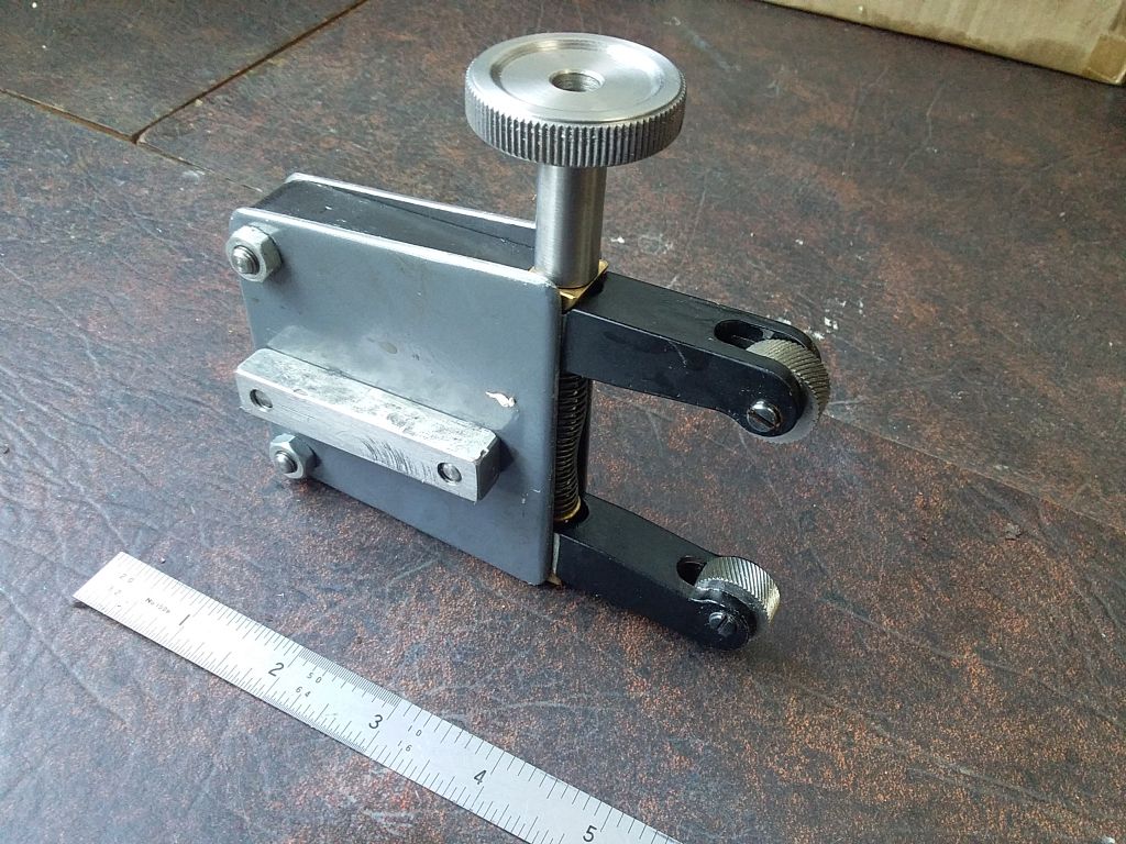
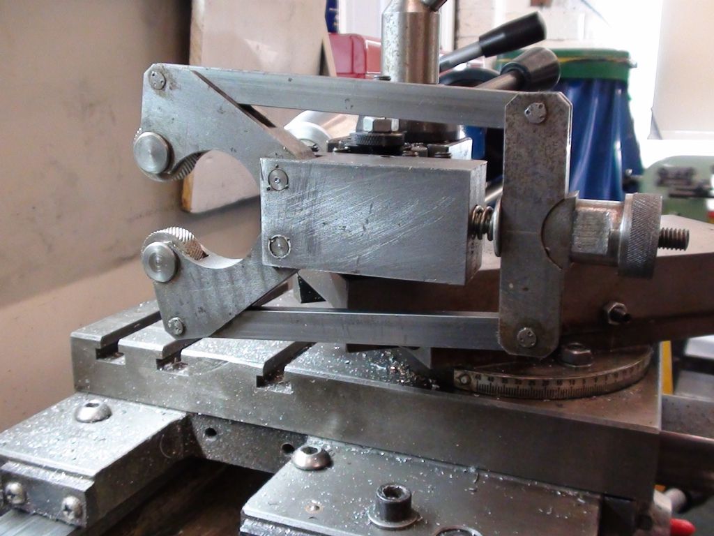
I also made my own knurling tool with flat plates on either side to hold the arms in place and in line. Found the drawings on the net somewhere. It is similar to the Hemingway Kits one.
Are you knurling at slow speed? I always use backgear, about 90rpm or less. And plenty of oil on the job constantly.
It also helps to take a skim cut over the job before knurling to make sure the surface is running nice and smooth and true.
Try some practice knurling on some bits of scrap mild steel. It can take a few goes to get the hang of it.
Yes but that’s cut knurling Noel a very different animal to most of our tools that are available. I find that your scissor type knurled needs to be used with a bit of panache so be brave and put the pressure on fairly quickly to allow the wheels to work together giving you a clean finish. I must admit that I seem to do my knurling at a higher speed than most people I have talked to but whatever suits you is all that matter as long as you get a result.
This is the one I made, from drawings found I dont remember where on the internet but I think it is the same as the one in MEW issue 72. Those 3mm thick flat side plates stop the arms flexing or wandering, and also form the main frame of the tool so it is very simple to make. I have been very happy with it.
The cheap Chinese knurling wheels i used seem to be very good.
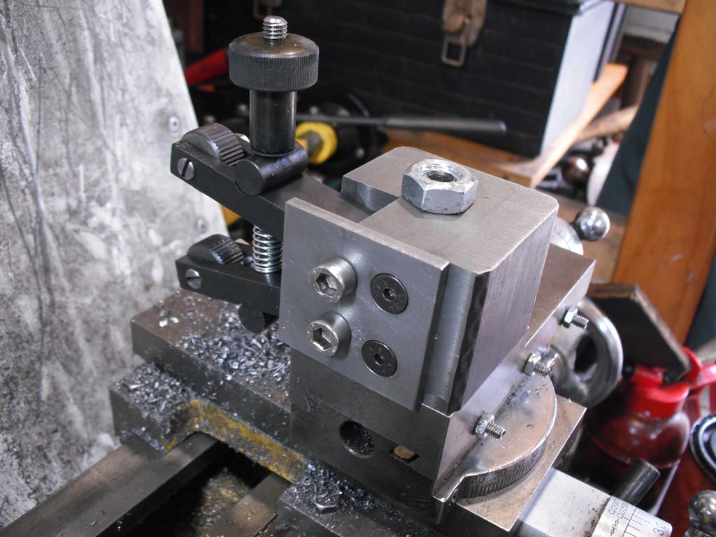
A picture of your tool and how you have it set up would be useful., make sure the toolpost is not rotating as you wind the tool into the work and pushing ir out of square.
As one that does not have a great need for knurling I just use one of the "short arms at 45deg" ones I bought some time ago, may not be upto cut knurling standards but does the job for me, bit of 20mm EN1A.
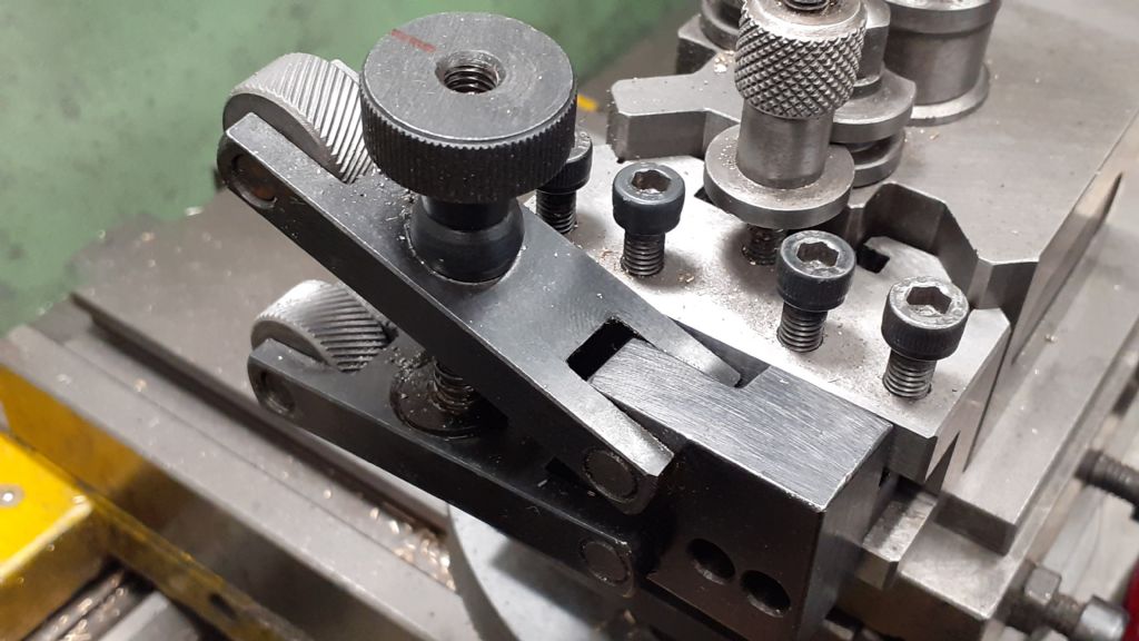
here is a close up picture as requested, also the steel is EN1A so not hard , I had tool on centre of bar, here is a picture of my tool and I did use cutting oil, I have gout in my hands so I probably was not able to turn the knob enough due to lack of grip, I have noticed that even though the tool is new there is some play of the knurling wheels on there shafts, it looks to be the same tool as JasobB is using and his has turned out fine.
Loose fit of the wheels on their spindles is ok. Stops them jamming up and any slack is taken up by the force on the wheels. I have the same problem with the knurled adjuster knob on my knurling tool too. I think there is a T-bar in its future as my hands are unlikely to get any better at this stage. Looks like you could drill a hole through yours and insert a bit of silver steel rod as a T bar for easier leverage.
Play around with it on some scrap trying the things suggested in posts above and you will get a method worked out that suits you and your equipment I am sure.
Re the skewing comments above, I have had trouble with the Myford toolpost rotating under pressure sometimes. But if you nip it good and tight and take care to set the knurling wheels as close as you can to the 12 and 6 o'clock positions on the job, it should stay put.
PS One thing to note in the Joe Pie video above is his warning to be VERY careful about putting anything near the knurl and knurl wheel contact point under power. Fingers, brushes, oil can nozzles, rags, whatever, will get sucked in between the knurl wheel and the job and nothing will stop it until it comes out the other side. Don't ask me how I know this! (Luckily it was a brush and not my finger. But it cured me of the habit of feeling how sharp the points on my knurling were while the job was still in progress. )
Del, yours looks exactly the same as mine. What I do is set the height so both arms are approx at equal angles, just bring the wheels to contact at 12 and 6 oclock then back off and wind the adjusting screw in then advance the tool to ctr or I can just feel it going over ctr. If not deep enough back it out and adjust the screw some more, etc.
That way you are not trying to close the wheels up under load with that small knob
I seem to remember Graham Meeke [sic] came up with a pretty nifty knurling tool. Perhaps he'll comment.
No comment from himself, yet, so I'll post a picture of the one I made to Graham Meek's design, originally published in, I think, Engineering in Miniature. I don't recall where I got the plans from unfortunately.
In my experience, it works extremely well and the added advantages over other designs are the much wider throat to accommodate large diameter workpieces and the provision of flats on the adjusting nut which allows a high degree of pressure to bear on the knurls during operation using a spanner. Although mostly used on brass, I have also used it on BMS to equally good effect.
Hopper: That article was the first one I ever submitted for publication .I'm pleased you're happy with it. A couple of people at my club made one, but I had no idea if anyone else had bothered.
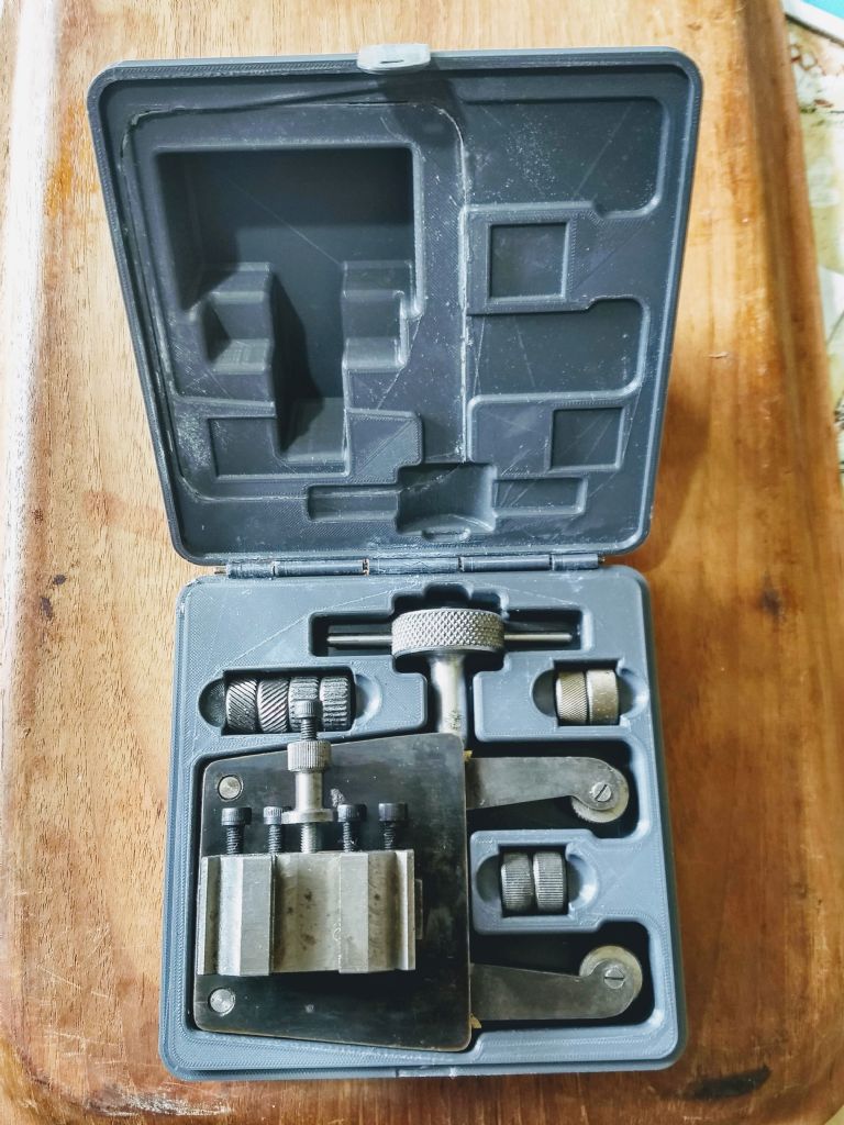
I got some different sized knurl wheels but had problems keeping everything together, so designed and 3D printed a fitted case for it all.
I seem to remember Graham Meek came up with a pretty nifty knurling tool. Perhaps he'll comment.
From what I can see in the OP's photograph it would seem the Knurls have been presented to the work in the centre of the diameter to be knurled.
This is not something I would do.
I have detailed my method elsewhere on the forum under a similar heading. Perhaps one kind Moderator might provide a link?
The pattern shown in the workpiece left by the wheels leads me to think the axles are not parallel to the work axis in both the horizontal and vertical planes. (This may be a defect in the tool construction, or mounting). This is a critical requirement with scissors knurling tools. Also critical is the side to side movement of the arms of the knurling tool. Each wheel is fighting to move sideways due to the resultant forces involved. The wheels are no different to a Helical Gear and these need to be paired in a gearbox to cancel out axial forces. Any play in the arms will therefore be exploited by the knurls at the expense of the finished knurling.
Small diameters usually benefit from straight knurling.
Clamp the knurling wheels on to the so they contact at points 7 and 11 o'clock looking from the tailstock. I appreciate your hand problem, so now you feed in on the cross slide. The force from the cross slide is greatly multiplied as the knurl wheels ride up toward the 6 and 12 o'clock points.
Gary,
I just have to ask what nicely knurled widget in photo 3 is for?
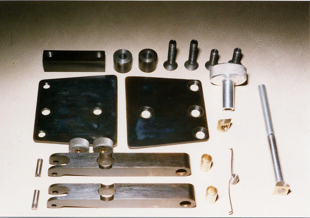
Mentioned above by Graham Meek, the sideways movement of the arms can cause poor / uneven knurls. I built the device shown below which is designed to eliminate sideways arm movement. Shown with straight knurls, but there are various interchangeable sets of wheels.