Graduating a Hemingway Taper Turning Attachment

Advert

Graduating a Hemingway Taper Turning Attachment

Home Forums Workshop Techniques Graduating a Hemingway Taper Turning Attachment

Viewing 24 posts - 1 through 24 (of 24 total)
  • Author
    Posts
  • #620060
    Mike Donnerstag
    Participant
      @mikedonnerstag

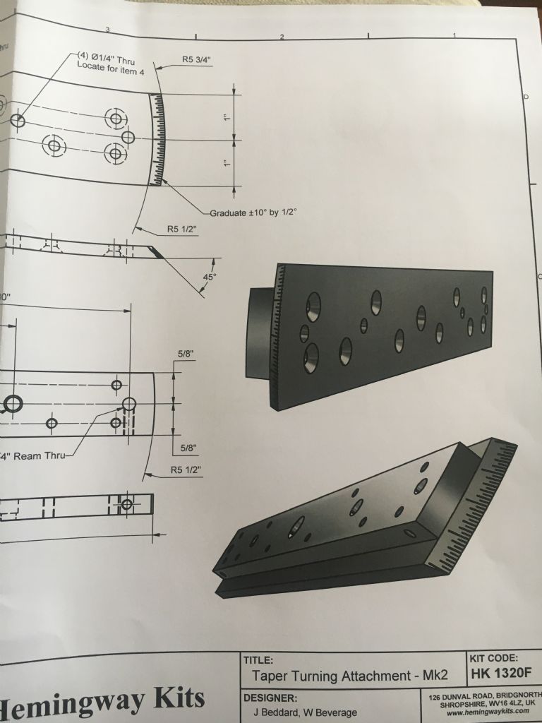
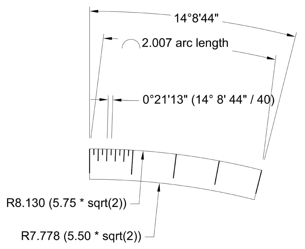
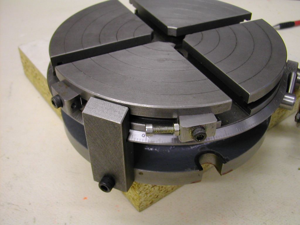
      I have the Hemingway Taper Turning Attachment (not the one that offsets the tailstock). However, the instructions give little advice on how to put the ‘coarse’ graduations on the end of the guide bar. These graduations have to be made at a 45deg angle on the end of a bar around 11.5” long at a radius of 5.75”, engraving from large to small radius, as shown in the drawing below.

      I’d be really interested to know whether this can be achieved with a small milling machine (Sieg SX3) and rotary table (I don’t yet have one, but intend to purchase a 6in one).

      img_4129.jpg

      Any advice gratefully received.
      Many thanks,

      Mike

      Edited By Mike Donnerstag on 07/11/2022 11:08:42

      Advert
      #16409
      Mike Donnerstag
      Participant
        @mikedonnerstag
        #620063
        John Haine
        Participant
          @johnhaine32865

          I must say that given the difficulty of making this, which would seem to need a way to hold a dividing head at a 45* angle, I think the design is not very well though out. I'd be inclined to machine the arc vertically on the end of the bar and put the scale on the top surface with a small block for the fiducial mark.

          But actually, is the scale likely to be very useful?  You could always use a protractor to set the angle.

          Edited By John Haine on 07/11/2022 11:30:26

          #620066
          Michael Gilligan
          Participant
            @michaelgilligan61133

            Thanks for posting the picture, Mike

            I nearly made a suggestion when you asked the question on the other thread … but it is now evident that I had mis-interpreted your text.

            I am definitely with John on this

            As drawn, it is a very poor piece of ‘design for production’

            MichaelG.

            #620068
            John Hinkley
            Participant
              @johnhinkley26699

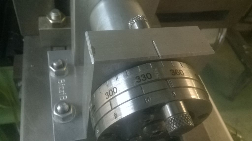
              I'm with John Haine and MichaelG on this, but if you are determined to follow the original design, as a temporary measure, you could print the lines on clear decal printing paper sheet and cut it out to apply it to the surface. I did this when I made my simple indexer, for the 10° marks on the "vernier" wheel. Here's how it turned out:

              Numbers stamped-printed

              The lines were put on with an engraving tool in the mill – it's the numbers that are printed. In you case it would involve a bit of jiggery-pokery in CAD to get the wrap-around shape, but it is doable.

              John

              #620069
              Tony Pratt 1
              Participant
                @tonypratt1
                Posted by John Haine on 07/11/2022 11:29:30:

                I must say that given the difficulty of making this, which would seem to need a way to hold a dividing head at a 45* angle, I think the design is not very well though out. I'd be inclined to machine the arc vertically on the end of the bar and put the scale on the top surface with a small block for the fiducial mark.

                But actually, is the scale likely to be very useful? You could always use a protractor to set the angle.

                Edited By John Haine on 07/11/2022 11:30:26

                The majority of dividing heads will swivel to 45 degrees.

                Tony

                #620070
                Ramon Wilson
                Participant
                  @ramonwilson3

                  Whilst I agree this is not the best of design from a manufacture point of view if the rotary table can be mounted vertically as some can or against an angle plate (as I do for similar instances) then it should be easy enough to do if the mounting of the RT can be swung across the table at the desired angle. A rotating single point cutter should do the job as long as everything is set on the RT centre line.

                  Tug

                  #620073
                  DiogenesII
                  Participant
                    @diogenesii

                    Mmmm.. ..oo.. ..er.. I see the SX3 has a tilting head.. ..so can you mount the workpiece flat on a R/T and side-mill the ends, then lock the spindle and use the quill feed to 'plane' the divisions with a single point tool whilst still in the same setup..?

                    ..it'll be a bit iffy, also you might need to do a dry run and see if you have room…

                    ..maybe a tooling plate / inventive supports to firm it all up..

                    EDIT – looking at the drawing, maybe you could use the upper 'beam' as a support for the machining by temp. re-attaching it below.. ..or something..

                    Edited By DiogenesII on 07/11/2022 13:23:43

                    Edited By DiogenesII on 07/11/2022 13:25:07

                    Edited By DiogenesII on 07/11/2022 13:29:40

                    #620078
                    Ramon Wilson
                    Participant
                      @ramonwilson3

                      Using the tilted head would be another option – I don't have that luxury on my Linley. Were I to do it the RT would be mounted vertically and set to one axis of the mill at the required angle to match the angle on the part.

                      The workpiece – plate – is set horizontal on the C/L of the R/T with the radius and angle pre machined and set such that the radius matches the arc of rotation. The cutter is set dead on centre height and the grooving done as if cutting a gear by moving the relevant axis, depth of cut provided by the other axis. If the spindle can be locked (not usual I agree) then the cutter can just scribe the work.

                      Not an ideal set up I agree too but something that can be done.

                      Tug


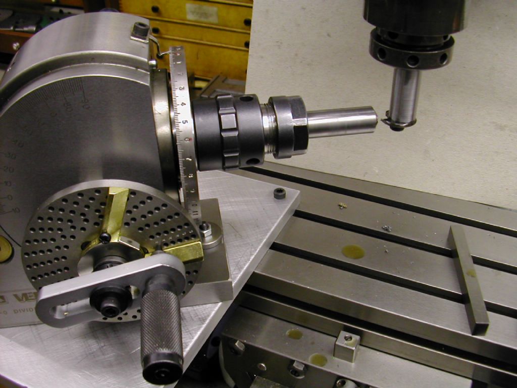
                      PS just found this – similar to this set up for cutting bevel gears

                      dscn4095.jpg

                      Div Head set a an angle to axis as suggested – as you can see a sub plate was required in order to enable this to be achieved

                      Edited By Ramon Wilson on 07/11/2022 13:56:01

                      Edited By Ramon Wilson on 07/11/2022 13:59:01

                      #620080
                      John Haine
                      Participant
                        @johnhaine32865

                        Apart from the difficulty challenge of machining I can't see any benefit except that one can possibly put the fiducial mark on a flat surface. As far as reading the scale is concerned it must be easier to look down on on a graduated scale rather than look obliquely.

                        #620089
                        DC31k
                        Participant
                          @dc31k
                          Posted by John Hinkley on 07/11/2022 12:21:57:

                          …if you are determined to follow the original design, as a temporary measure, you could print the lines on clear decal printing paper sheet and cut it out to apply it to the surface.

                          Your picture shows the graduations on the surface of a cylinder. The ones he needs are on the surface of a cone. The printed paper will either wrinkle up at the top or rip apart at the bottom.

                          #620092
                          Michael Gilligan
                          Participant
                            @michaelgilligan61133
                            Posted by DC31k on 07/11/2022 16:05:44:

                            Posted by John Hinkley on 07/11/2022 12:21:57:

                            …if you are determined to follow the original design, as a temporary measure, you could print the lines on clear decal printing paper sheet and cut it out to apply it to the surface.

                            Your picture shows the graduations on the surface of a cylinder. The ones he needs are on the surface of a cone. The printed paper will either wrinkle up at the top or rip apart at the bottom.

                            .

                            … I think John is probably aware of that ^^^

                            His post goes on to say: “ … it would involve a bit of jiggery-pokery in CAD to get the wrap-around shape, but it is doable.”

                            MichaelG.

                            #620095
                            John Hinkley
                            Participant
                              @johnhinkley26699

                              Precisely, Michael. I have vague memories of a function in one of my cad programs that will wrap text along a path (truncated cone), but at the time of my response couldn't recall it. As the OP has had ample solutions proposed, I didn't think that it was worth further investigation.

                              John

                              #620097
                              bernard towers
                              Participant
                                @bernardtowers37738

                                Colchester never had a problem when making theirs. possibly that's were the idea was filched from.

                                #620176
                                John Hinkley
                                Participant
                                  @johnhinkley26699

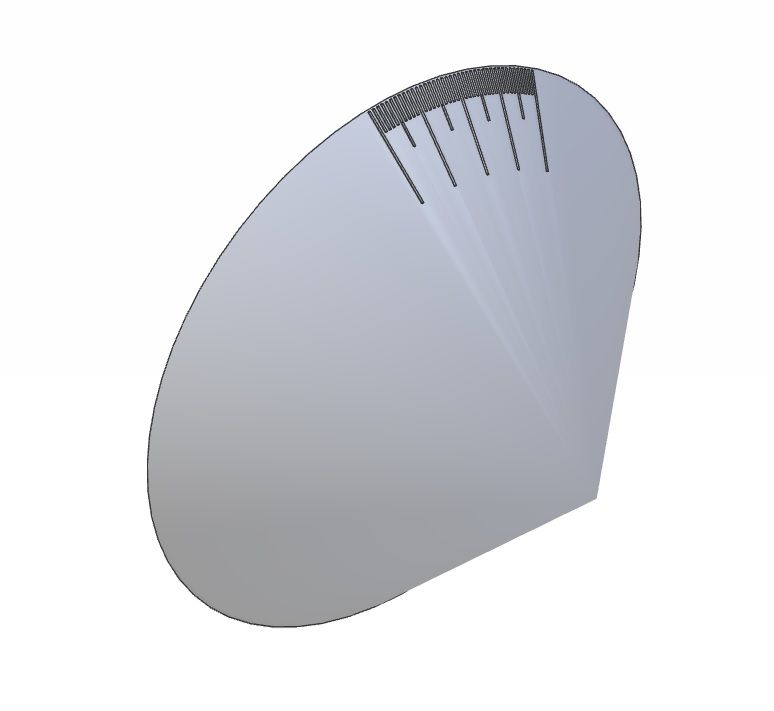
                                  Like a dog with a bone, I'm back! I created a pattern of graduations on a 45° cone in Alibre Atom:

                                  conical graduations

                                  And there it stumped me. There is an add-on in Alibre Expert which will convert that 3D shape to sheet metal – i.e. "flatten it out" – but this is not available for Atom. I tried exporting it as a STEP file to Fusion 360, but – guess what? – you have to upgrade to get the sheet metal conversion function. So it can be done, but other, better, solutions have already been postulated. This was just an exercise for the grey matter from my point of view.

                                  John


                                  Edited By John Hinkley on 08/11/2022 10:44:47

                                  #620190
                                  DC31k
                                  Participant
                                    @dc31k
                                    Posted by John Hinkley on 08/11/2022 10:44:11:

                                    Like a dog with a bone, I'm back! I created a pattern of graduations on a 45° cone in Alibre Atom:

                                    As an alternative to 3D CAD that you have to pay to upgrade, please consider this low-tech method:

                                    O-level technical drawing with a sheet of paper, a graduated straightedge and pair of compasses would get you a development of the cone. A bit of trigonometry would tell you the included angle of this development. This included angle represents the circumference of the cone base.

                                    You can then work out the chord length for 1 (or 5 or 10) degree(s) around it and step off with dividers. This is the only fiddly bit of the process and where simple and free 2D CAD would assist. Join each of your pricks to the vertex for the lines.

                                    #620202
                                    Hopper
                                    Participant
                                      @hopper

                                      Rather than set up on a rotary table to index the graduations, could you not instead rely on the taper turning attachment's own inbuilt micrometer adjustment screw? This will move the slide bar by very fine increments to whatever degree setting you desire. You would then only have to set the taper-turning attachment's base at a 45 degree angle on the mill table and clamp it down and then use an engraving cutter in the mill spindle to engrave the line. It could be set so the attachment is hanging half off the table, thus reducing head height to less than 5 inches or so.

                                      Or even do a similar thing mounting the taper turning attachment at 45 degrees horizontally on the T slotted cross slide of a Myford lathe and hold your engraving cutter in the chuck, using the cross slide for length of cut and the saddle movement for depth of cut via leadscrew hand wheel. All the while using the attachment's own micrometer adjusting screw to vary the angle for each graduation.

                                      Or you could even clamp the attachment to the bed of the lathe with suitable height packing, laid down horizontally, and use a simple lathe toolbit sharpened to a V and held in the toolpost to engrave the graduations by racking the carriage back and forth like a hand-shaper or planer. Depth of cut would be set by cross slide. Line length by carriage stop. Graduations by the attachments micrometer screw again.

                                      Edited By Hopper on 08/11/2022 12:03:43

                                      #620230
                                      DC31k
                                      Participant
                                        @dc31k

                                        As the atom-ic sledgehammer has not cracked this nut, please see below for development of cone, which would allow the scale to be engraved on the flat:

                                        taper turning scale.jpg

                                        Note that the 2" width on the drawing is very slightly over 20 degrees included angle, so the outer graduations will not coincide with the edge of the metal.

                                        #620250
                                        John Haine
                                        Participant
                                          @johnhaine32865

                                          I must say I'm bemused by all this discussion of "how" while ignoring the question of "why". Even if you have a scale I think it's of doubtful value.

                                          • The most common taper we cut is probably MT2 and an angle scale just isn't precise enough to do that, you have to use a DTI to get zero movement when winding the saddle backwards and forwards. Someone pointed out above that they keep their TTA set to MT2 anyway (or use a sine bar).
                                          • OK, if you just want an approximate taper then a scale is useful for quick setting, but…
                                          • …just how often do we cut long tapers anyway?
                                          • It should be simple to arrange a gadget to allow a protractor to be used to set the angle against a test bar or similar when you do want to make a taper.
                                          • If you make the scale on a piece of paper it will get soaked in coolant and probably peel off. You could make it on a bit of shim somehow, but then it needs to be fixed, and anyway if it's on a sloping face it's harder to read as I pointed out.

                                          If you want a machining challenge by all means find a way to engrave the scale obliquely, but if you just want to make tapers don't bother in my view, or engrave it on the flat top face.

                                          #620251
                                          Mike Donnerstag
                                          Participant
                                            @mikedonnerstag

                                            Thanks to everyone who posted a reply – plenty of options! I looked at the Hemingway drawing and notes and just thought, "How the heck do I do this, with my setup? Am I missing something??". These things play on my mind, so it's really great to use this forum to get information from those far more knowledgeable than I!

                                            I intend to ignore the 'coarse scale' for now, as John Haine suggested. It seems that the attachment, especially with the micrometer adjustment, doesn't really need the coarse scale. If I find it necessary (or an interesting-enough exercise), I suppose I can always add it at a later date.

                                            Mike

                                            #620252
                                            old mart
                                            Participant
                                              @oldmart

                                              The scale on the Smart & Brown model A taper turning attachment which is pretty much identical to the one on the later 1024 lathes is not calibrated anywhere finely enough to produce Morse tapers, you just have to creep up on the exact fit. Even using a DTI exactly on the centreline is no guarantee of the perfect taper. A vernier scale giving a resolution of 1 minute of arc (1/60th of a degree) will only get you close, and only having the mating part will get you a perfect fit. That is what is so annoying about Morse tapers, you get one perfect, but every size is a different taper.

                                              #620264
                                              Ramon Wilson
                                              Participant
                                                @ramonwilson3

                                                Mike – just a further note on a practical application.

                                                I did this 360 degree ring for my RT on the lathe using the change gears for division and a detent.

                                                dscn2609.jpg


                                                The engraving was carried out with a cross slide mounted slotting tool but could, if a lot slower, have been done using the top slide. The change gears may not be as accurate on division for your taper turning needs but does show you that you do have the means.

                                                Certainly sounds like you do so why not have a go at itsmiley


                                                Tug

                                                Edited By Ramon Wilson on 08/11/2022 18:20:54

                                                #620331
                                                duncan webster 1
                                                Participant
                                                  @duncanwebster1

                                                  Removed

                                                  Edited By duncan webster on 08/11/2022 23:43:11

                                                  #620332
                                                  Hopper
                                                  Participant
                                                    @hopper

                                                    I think the graduations are only meant as a rough guide starting point for any kind of precision taper such as Morse etc. Trial and error and fine adjustment with the micrometer screw are usually needed for that. If you do set it up to turn a morse taper, you could scribe a reference line on the end of the slide bar for future reference.

                                                    The coarse graduations might be ok for tapers such as the pillar on a beam engine etc that is purely aesthetic and not fitting into another taper etc.

                                                    It would still be an interesting exercise to engrave the marks using the attachment's own micrometer.

                                                    Or looking at Ramon's RT graduated in the lathe using change gears, you could do something similar by mounting your slide bar on the lathe face plate and setting your change gears and a detente to give 360 graduations and then engrave a line every 1 degree using at toolbit laid sideways in the toolpost and the topslide to move it at the required angle. You could set it to 720 graduations and do half degrees too.

                                                  Viewing 24 posts - 1 through 24 (of 24 total)
                                                  • Please log in to reply to this topic. Registering is free and easy using the links on the menu at the top of this page.

                                                  Advert

                                                  Latest Replies

                                                  Home Forums Workshop Techniques Topics

                                                  Viewing 25 topics - 1 through 25 (of 25 total)
                                                  Viewing 25 topics - 1 through 25 (of 25 total)

                                                  View full reply list.

                                                  Advert

                                                  Newsletter Sign-up