Gear cutters for clock wheels

Advert

Gear cutters for clock wheels

Home Forums Workshop Techniques Gear cutters for clock wheels

Viewing 25 posts - 1 through 25 (of 64 total)
  • Author
    Posts
  • #584499
    Jouke van der Veen
    Participant
      @joukevanderveen72935

      Dear forum members,

      Could you have a look at my album “Radius tool for gear cutter”?

      I am open for comments and suggestions.

      Accuracy of tooth thickness of gear cutter has to be improved, at least.

      Regards,

      Jouke

      Advert
      #16353
      Jouke van der Veen
      Participant
        @joukevanderveen72935

        How to achieve a constant tooth thickness

        #584501
        Martin Kyte
        Participant
          @martinkyte99762

          Well thats an interesting twist. You are a little limited on diameter with that method. What's wrong with turning tapered buttons in silver steel. With a parallel waist they can be accurately positioned in holes drilled in the end of the button holder, whitch is put in on the mill will correctly separate two buttons to give the correct thickness to the gear cutter. High Strength loctite to cement in place means that you don't loose the polish on the buttons as you don't have to apply heat to silver solder them in place.

          regards Martin

          #584502
          John P
          Participant
            @johnp77052

            Posted by Jouke van der Veen 07/02/2022 21:42:17

            Dear forum members,

            Could you have a look at my album “Radius tool for gear cutter”?

            I am open for comments and suggestions.

            Accuracy of tooth thickness of gear cutter has to be improved, at least.

            Regards,

            Jouke

            Varying tooth thickness ,cause the sides of the cutter blank not
            parallel.

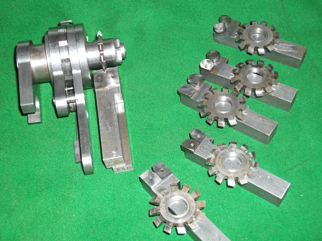
            Build a Eureka device and or make a two button tool
            to cut both sides of the gear cutter at the same time.

            John

            eureka 1.jpg

            #584503
            Jouke van der Veen
            Participant
              @joukevanderveen72935

              Hallo Martin,

              I considered the method you described more than once.

              I recognise that having such a tool woul result in e constant tooth thickness but I think I willl not be able to postion two buttons at a, lets say, precise distance of 3×1.57 = 4.71mm. How precise has this to be? What do you exactly mean with a parallel waist?

              Regards,

              Jouke

              #584507
              Jouke van der Veen
              Participant
                @joukevanderveen72935

                Hallo John,

                I think you are right. On the other hand I think an Eureka device is a step to far for me.

                I preshaped the gear cutter with a “standard” cutting tool in 8 steps to a tooth thickness of (approx.) 1.7mm.

                Then I changed over to the radius tool and needed again 8 steps, of course, to reach the final thickness of 1.57mm

                With this method I had to repostion the gear cutter on the excentric mandrel several times.

                It was my second trial. I started with a M1.27 in mild steel with a less precise result. The second trial was the M1.0 shown in this topic. I am convinced that I can do better. But remember, I have to do this on an Emco Compact 5.

                How accurate should tooth thickness be?

                Regards, Jouke

                Edited By Jouke van der Veen on 07/02/2022 22:37:25

                #584508
                Huub
                Participant
                  @huub

                  I assume you are making involute gear cutters using the "button method".

                  I make single tooth versions on my CNC lathe. I measure the tooth thickness using a caliper. I set the caliper to the requested diameter + 0.1 mm. The cutter tip should "lock" between the "legs" (don't know the English word) of the caliper. Then I set the gap 0.1 mm smaller than the requested size. Now it should not be possible to "lock" the tip of the gear between the "legs" of the caliper. By changing the gap between the "legs", I can "measure" very repeatable the tip of the gear.

                  I also made these cutters on the milling machine. An end mill is used as "Button". Instead of calculating the button diameter for the gear cutter to make, I calculate the the number teeth, based on the end mill diameter.

                  A 4 mm end mill can make a Modul 1 cutter for 12 (11.7) teeth and more.

                  A 5 mm end mill can make a Modul 1 cutter for 15 (14.6) teeth and more.

                  A 20 mm end mill can make a Modul 1 cutter for 59 (58,5) teeth and more.


                  Edited By Huub Buis on 07/02/2022 22:48:35

                  #584542
                  Martin Kyte
                  Participant
                    @martinkyte99762
                    Posted by Jouke van der Veen on 07/02/2022 22:09:25:

                    Hallo Martin,

                    I considered the method you described more than once.

                    I recognise that having such a tool woul result in e constant tooth thickness but I think I willl not be able to postion two buttons at a, lets say, precise distance of 3×1.57 = 4.71mm. How precise has this to be? What do you exactly mean with a parallel waist?

                    Regards,

                    Jouke

                    Using the analogy of a buttercup flower where the tapered sided button is the 'cup' and the waist is the much smaller 'stem'. If you drill your locating holes on the mill they can be located with precision using the dials or DRO.

                    regards Martin

                    #584550
                    John Haine
                    Participant
                      @johnhaine32865

                      Given that clock gear designs have quite a lot of clearance, how precise does the width have to be?

                      #584552
                      Jouke van der Veen
                      Participant
                        @joukevanderveen72935

                        I measured the original thickness of the gear cutter at the “foot” of the teeth. Thickness varies between 4.72 and 4.77mm. So, the cutter blank is not optimal parallel, as John said.These differences cause a varying and larger offset of the tooth tips when the gear is mounted in its 4 positions. This needs improvement, at least.

                        Huub, I have to study your method before coming with a proper answer. My restriction is that I have to work with an Emco Compact 5 including its milling column in their original outfit. As many clock builders did. 😉

                        #584553
                        Jouke van der Veen
                        Participant
                          @joukevanderveen72935

                          Double

                          Edited By Jouke van der Veen on 08/02/2022 09:15:01

                          #584559
                          Jouke van der Veen
                          Participant
                            @joukevanderveen72935

                            John,

                            That is also my question. Cutter dimensions are specified two digits behind the point.

                            Example: M1: 1.57mm tooth tip, etc. But where do gear cutter makers end up with their final product?

                            In other words, my cutter, after some additional improvement, may be good enough. I would like to get some response on this.

                            On the other hand it would be a bad experience to have made a set of clock wheels, and then, after assembling, coming to the conclusion that they are not accurate enough!


                            Edited By Jouke van der Veen on 08/02/2022 10:07:09

                            #584568
                            John Haine
                            Participant
                              @johnhaine32865

                              You might look at this website. It designs "cycloidal" gear pairs based on standard profiles.

                              You can see immediately the clearance that the standards recommend. I've built a gear train based on the dxf files this generates, exported to a CAM program to actually generate g-code for a CNC mill, and they work well direct from the mill using the calculated centre-centre distance.

                              If you have the use of a 3D CAD program (such as Solid Edge or Fusion 360) you could import the dxfs and animate the gear pair to investigate the impact of tolerances.

                              #584580
                              Huub
                              Participant
                                @huub
                                Posted by Jouke van der Veen on 08/02/2022 09:51:59:

                                Cutter dimensions are specified two digits behind the point.

                                Your cutting depth = D+f = 2.16 for a Modul 1 gear. The 0.16 (extra cutting depth) creates play between the gears. If you have a 20° pressure angle, this results in a clearance at 1 flank of (tan 20 x 0.16) 0.06 mm. At the 4 flanks there is 0.23 mm clearance total.

                                A 12 teeth Module 1 gear has a tip of 1.10 mm.

                                A 60 teeth Module 1 gear has a tip of 0.82 mm.

                                #584596
                                John P
                                Participant
                                  @johnp77052

                                  Posted by Jouke van der Veen 07/02/2022 22:35:10

                                  Hallo John,

                                  I think you are right. On the other hand I think an Eureka device is a step to far for me.
                                  I preshaped the gear cutter with a “standard” cutting tool in 8 steps to a tooth thickness
                                  of (approx.) 1.7mm.Then I changed over to the radius tool and needed again
                                  8 steps, of course, to reach the final thickness of 1.57mm
                                  With this method I had to repostion the gear cutter on the excentric mandrel
                                  several times.It was my second trial. I started with a M1.27 in mild steel with
                                  a less precise result. The second trial was the M1.0 shown in this topic. I am
                                  convinced that I can do better. But remember, I have to do this on an Emco Compact 5.
                                  How accurate should tooth thickness be?

                                  Regards, Jouke

                                  A lot of your problems can be resolved by boring and facing one side
                                  of the cutter blank and marking that side and later on using this side
                                  as the datum for mounting the blank of the finished cutter on the arbor.
                                  The other side of the blank must be parallel to the datum side to
                                  0.00 or as close as.

                                  Secondly a two button tool will automatically give a constant width
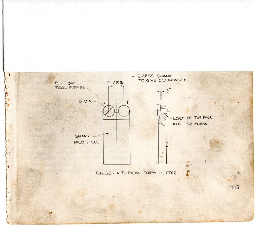
                                  on all of the cutting teeth. Referring back to the photo in my previous post
                                  these 2 button tools some have parallel turned buttons that are hardened
                                  and then loctited into the holder,in the absence of a dro system a cheap
                                  clock gauge about £10 from China can easily be set up to give the
                                  required spacing, a metric clock gauge reading in .01 can be easily
                                  read to subdivide that to half or quarters.
                                  The holder seen here is the one in the book Gears and gear cutting
                                  and the clearance is provided by the 5 deg angle on the front.
                                  The only problem that you face then is the minimum spindle speed
                                  of your lathe which seems to be around 200 rpm ,to cut silver steel
                                  with hardened silver steel tooling at the diameter that you have you would
                                  need to be below 50 rpm , if you are unable to make adjustment to the
                                  machine to get down to these speeds the next best thing is to
                                  use a mandrel handle.Coating the tooling and cutter blank with RTD
                                  will make it a lot easier.

                                  John

                                  gear cutter button tool.jpg

                                  #584661
                                  Jouke van der Veen
                                  Participant
                                    @joukevanderveen72935

                                    Hallo Huub,

                                    I understand that with your caliper check you can work wit an accuracy < 0.1mm for measuring gear tooth thickness, but not down to 0.01mm.

                                    In the milling method you describe tooth foot radii are shaped with the appropriate end mill diameter.
                                    I did not yet check if I can reproduce your method. For instance, I do not understand how you can make a M1 58 teeth gear cutter with a 20mm end mill. Is this a typing error?

                                    in your following response you speak about gear tips of 1.1 and .82mm I expect these are for involute gearsand not cycloidal.

                                    Regards, Jouke

                                    #584662
                                    Jouke van der Veen
                                    Participant
                                      @joukevanderveen72935

                                      Dear John H,

                                      I have to study the website you refer to. It will be helpfull. I have no experience with CAD/CAM software. Thank you for the information about how get a better insight in tolerances for gear wheels.

                                      Regards, Jouke

                                      #584667
                                      Jouke van der Veen
                                      Participant
                                        @joukevanderveen72935

                                        Dear John P,

                                        I will apply your proposed cutting sequence on the next gear cutter to be made: pre-cutting followed by finish cutting on one side of the blank and then repeat this on the other side, starting from a real parallel blank. I think I will do this with my “one-button” tool. This tool has the benefit of giving a precise radius after a simple grinding step.
                                        If this does does not work at all for me than I should switch over to the two-button cutter. But I know that generations of clock makers must have used methods equivalent to the one-button method.
                                        I have a measuring clock available, and a digital caliper that can be magnetically clamped on the lathe.

                                        I think, I have now a lot of input that will help me to improve accuracy of my working methods and to give more insight in required tolerancies. Thank to all the contributors. I will keep you informed.

                                        Regards, Jouke

                                        Edited By Jouke van der Veen on 08/02/2022 20:23:44

                                        #584684
                                        lfoggy
                                        Participant
                                          @lfoggy

                                          Your cutters look very serviceable and will give consistent tooth geometry. A deviation in tooth thickness of a few hundredths of a mm from perfect is really not an issue. I have now built quite a few clocks and my experience is that they are quite forgiving of tooth geometry. Unless you are building an unusual very low-power or long duration clock it just won’t matter.

                                          To be honest though, I have gotten bored of making cutters myself and just buy them from PP Thornton. They last for ages (for ever if your are an amateur constructor) and can be resharpened easily. You can then get on with the task of making the clock…

                                          #584687
                                          Huub
                                          Participant
                                            @huub
                                            Posted by Jouke van der Veen on 08/02/2022 19:50:39:

                                            I understand that with your caliper check you can work wit an accuracy < 0.1mm for measuring gear tooth thickness, but not down to 0.01mm.

                                            My calipers aren't that accurate but i find repeatable results within 0.02 mm. You can do the same measurement using a micrometer.

                                            I make my gear cutters using a CNC lathe. Both sides of the gear cutter are cut using the same "parting style tool". This tool is a triangular insert tool at 0°. I prefer an insert tool because the nose radius gives a better finish. Also, insert tools are better suitable for cutting silver steel. You can also do this using an HSS parting tool or a L and R tool.
                                            The tip of the turned cutter is mostly within 0.03 mm of target.

                                            In the milling method you describe tooth foot radii are shaped with the appropriate end mill diameter.
                                            I did not yet check if I can reproduce your method. For instance, I do not understand how you can make a M1 58 teeth gear cutter with a 20mm end mill. Is this a typing error?

                                            No, this is not a typing error.
                                            You would normally use a #7 involute cutter that can cut gears having 55 teeth or more. If you would make this gear cutter using the button method, you would need a 18.81 mm button to shape this gear cutter.
                                            I do not have a 18.81 mm end mill (could use a cutter head). If I use a 16 mm end mill, I can make a 47 teeth or more gear cutter. If I use a 20 mm end mil, I can make a 59 or more teeth gear cutter.

                                            in your following response you speak about gear tips of 1.1 and .82mm I expect these are for involute gearsand not cycloidal.

                                            Yes, you are right, the numbers are for involute gears. I didn't realise that clock makers use cycloidal gears. I am going to read that chapter from Ivan Law (again).

                                            In both cases, the making of the gears are based on the button method. So you to should be able to produce these gear cutters using an end mil. On the lathe I turn the gear cutters using a spacer. This will give an eccentric tool path and this will create clearance on the cutting edges.

                                            On the mill I used a rotary table and placed the gear cutter blank eccentric.

                                            I can make the gear cutters also on my small HBM300 lathe, size doesn't matter.

                                            I have seen a YouTube video where they used a (tapered) drill for drilling holes in sheet metal. The tapered drill creates the clearance and it lets you choose "any size".

                                            If the thickness of the tip is a problem, feed the button 2 mm deeper. Than you can measure the thickness of the tip easier. When all is done, turn the tip 2 mm shorter.

                                            I am confident that you will be able to make gear cutters using the one button tool. So keep trying until you get it right.

                                            Regards, Huub

                                            #584814
                                            Jouke van der Veen
                                            Participant
                                              @joukevanderveen72935

                                              Hallo Huub,

                                              Now I understand your large end mill diameters. They are inherent to involute gears.

                                              I think I understand the effect of using a spacer for getting clearance on the side cutting edges. As you understand my cutters do not have a clearance for the parallel parts of the teeth. I think, however, they should have to get a “smoother” tooth cutting in brass.

                                              It would be nice to see some pictures showing your two ways of making gear cutters. These YouTube movies I just find on the Internet are yours I assume! I will have a look. Ijust saw something about gear cutting!

                                              You are right about making the parallel parts of cutting edges larger then specified length to start with. This will make measurements easier. As a last step you can turn the parallel parts down to the specified length. By the way I measure with a micrometer.

                                              Where do you live about in The Netherlands?

                                              Regards,

                                              Jouke


                                              Edited By Jouke van der Veen on 09/02/2022 20:36:22

                                              #584822
                                              Huub
                                              Participant
                                                @huub

                                                Jouke,

                                                As you understand my cutters do not have a clearance for the parallel parts of the teeth.
                                                To me, it seems you also turn the cutter eccentric. If the front of the cutter tip is tapered, you have clearance on all cutting edges.

                                                It would be nice to see some pictures showing your two ways of making gear cutters
                                                I will make some pictures of my setup on the lathe, the mil and a turned gear cutter at the end of this week.

                                                Where do you live about in The Netherlands
                                                I live in Hoensbroek, in the south of the Netherlands.

                                                If you can turn a radius on the lathe, you can turn these gear cutters without CNC. Compensating for the nose radius of the tool is not that complicated but you can avoid this by using a sharp HSS (parting) tool.

                                                Keep your tool as close to the tool post (less stickout) as possible. Turn the topslide as far backwards as possible. This gives a more rigid setup.

                                                I like your setup using a bearing in the steady rest, haven't seen this before!

                                                Regards, Huub

                                                #584934
                                                Jouke van der Veen
                                                Participant
                                                  @joukevanderveen72935

                                                  In the build-up to get experience in making clock wheel gear cutters I made some gear blanks in advance.

                                                  I turned them “parallel” in the independant 4-jaw chuck, not realizing that the back-face against the jaws does not have to be perpendicular to the axis of rotation. I measure thickness differences up to 0.05mm and conclude this is not parallel enough for cutting a constant tooth thickness, as John P already warned.

                                                  I would like to face these blanks again. Problem is that they already have an 8mm center hole for following operations.

                                                  Is it an idea to use a “super glue” chuck for facing. So, to face a disk of alu in the 4-chuck and then glue a blank to it and face it. Will the gap of super glue be small and constant enough so that I can get faces parallel (at least better than, lets say, 0.02mm)?.

                                                  I hope to hear from you.

                                                  Regards,

                                                  Jouke

                                                  #584944
                                                  Huub
                                                  Participant
                                                    @huub

                                                    Youke,

                                                    I measure thickness differences up to 0.05mm
                                                    I expected the difference a lot smaller because the backface of the chuck normally is quit good/flat.
                                                    If you clamp something against a surface, then after tightening, you should tap it lightly with a hammer (wood/plastic) to get rid of all play.

                                                    Is it an idea to use a “super glue” chuck for facing
                                                    If you face the alu this should give a result better than 0.02 mm. Beware that when the glue gets hot/warm the part gets off. You also have to remove all the glue (acetone or nail polish remover)
                                                    I normally use glue only for small parts that can't held by a chuck or collet.

                                                    You can measure the flatness of the chuck (after removing the claws) to see if this chuck really can be the cause of the problems.
                                                    If the chuck isn't flat you have to check the back of the chuck and the mounting plate for chips, burrs and other damage.

                                                    If I want thin parts turned really flat, I place a taper (having a long bar at the end) in the lathe and face it. Then I press the part against this this face when I clamp it in the 3 or 4 claw chuck. Normally, the flatness than is better than 0.01 mm.
                                                    I make the size of the bar just a bit smaller then the part to clamp. In the bigger lathe, I can place the taper without removing the chuck, in the small lathe, I have to remove the chuck first.

                                                    #584949
                                                    Jouke van der Veen
                                                    Participant
                                                      @joukevanderveen72935

                                                      A question.

                                                      Can I improve “parallelism” of cutter blanks by re-facing them against a so-called super-glue chuck? Is the bond gap constant enough to achieve a variation in thickness below, lets say, 0.02mm?

                                                      I made some stock which already have a 8mm center hole for futher operations. I measure thickness differences up to 0.05mm on these blanks. I agree with John P that this is a root cause for a non-constant tooth thickness of the final cutter.

                                                      I hope to hear from you.

                                                      Regards, Jouke

                                                    Viewing 25 posts - 1 through 25 (of 64 total)
                                                    • Please log in to reply to this topic. Registering is free and easy using the links on the menu at the top of this page.

                                                    Advert

                                                    Latest Replies

                                                    Home Forums Workshop Techniques Topics

                                                    Viewing 25 topics - 1 through 25 (of 25 total)
                                                    Viewing 25 topics - 1 through 25 (of 25 total)

                                                    View full reply list.

                                                    Advert

                                                    Newsletter Sign-up