Machining Radius

Advert

Machining Radius

Home Forums Workshop Techniques Machining Radius

Viewing 13 posts - 1 through 13 (of 13 total)
  • Author
    Posts
  • #557518
    Colin Heseltine
    Participant
      @colinheseltine48622

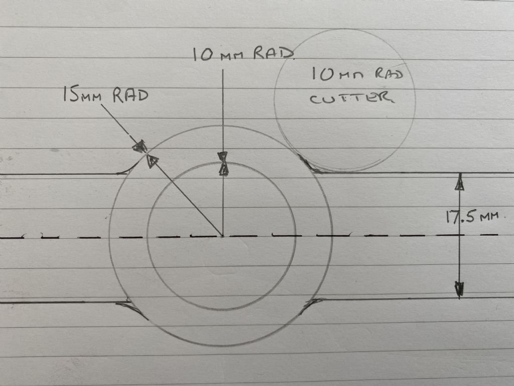
      img_0531.jpgI need to machine several radiuses on an aluminium bar, which will eventually end up as a gear lever for a sequential gearbox. Looking at the drawing above the 10mm diameter is a hole bored through the bar as a pivot. The outer sides of the bar are to have a radius of 15mm. The bar is 17.5 mm width.

      For the first radius, on the basis that I machine the bar from the right hand side 8.75mm above the centre line how do I calculate the point at which I cease travel of the X axis so that I can then blend into the 15mm radius. Assume that I use a 10mm radius cutter. My maths and geometry was never very good, plus it was over 55 years ago. I wouid assume that once I have a formula I can use this for the remaining radii.

      Thanks,

      Colin

      Edited By Colin Heseltine on 08/08/2021 12:09:42

      Advert
      #16305
      Colin Heseltine
      Participant
        @colinheseltine48622
        #557521
        speelwerk
        Participant
          @speelwerk

          You write that the cutter has a diameter of 10 mm but in the drawing you state a cutter with a 10 mm radius. it makes a difference. Niko.

          #557522
          Colin Heseltine
          Participant
            @colinheseltine48622

            Niko,

            Thanks. Corrected

            Colin

            #557524
            Peter Cook 6
            Participant
              @petercook6

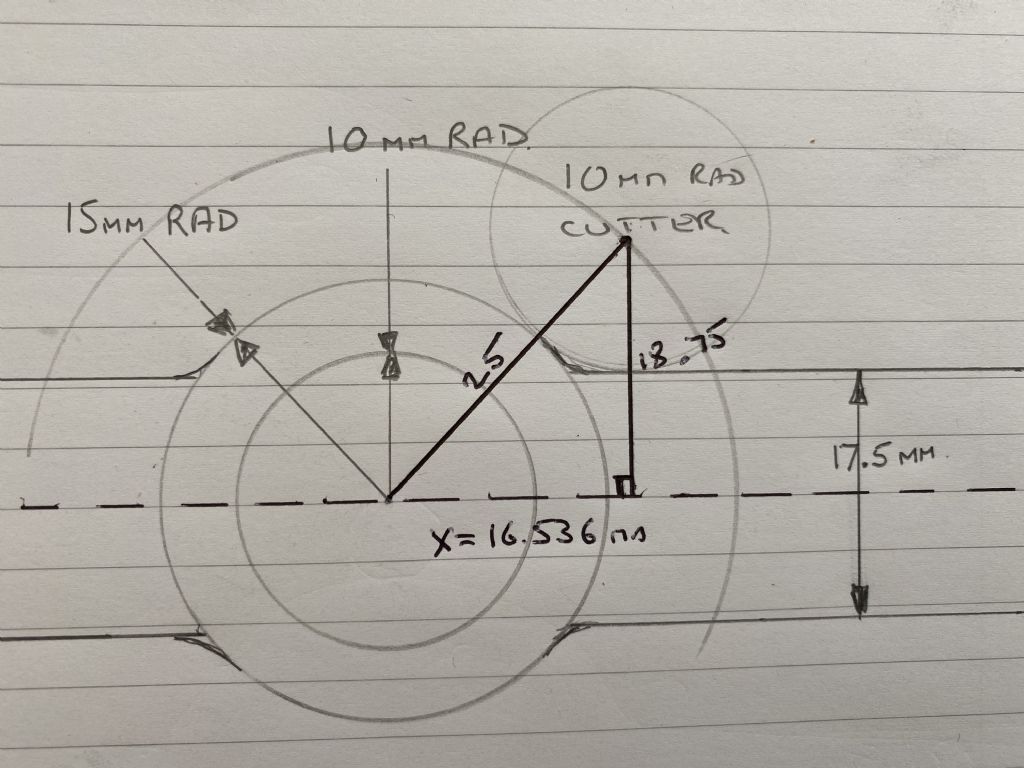
              Sorry my geometry is too rusty to develop the equations, but a quick sketch gives

              angle calculations.jpg

              #557525
              Dave Morgan 1
              Participant
                @davemorgan1

                To calculate the answer:

                1. Add the 15mm radius to the radius of the cutter, 15+10=25 and square the result = 625.

                2. Add half the thickness of the bar to the radius of the cutter, 8.75+10=18.75 and square the result = 351.5625

                3. Subtract the result of 2 from 1, 625 – 351.5625 = 273.4375 and take the square root of the result = 16.5359

                #557526
                Colin Heseltine
                Participant
                  @colinheseltine48622

                  Peter,

                  Many thanks for that. I was just looking through my Mothers copy of Machinery Handbook at the geometry propositions and thought back to something Joe Pieczinski said about it all works on triangles. So looked at my drawing, remembered Pythagorus's theorem (25 squared – 18.75 squared gives result of 273.44, which when square rooted give 16.536mm) and came of with figure of 16.536mm, which rather matches your 16.54mm. So between us you have answered my questions and I've amazingly also answered my own question.

                  img_0532.jpgThanks,

                  Colin

                  #557527
                  Colin Heseltine
                  Participant
                    @colinheseltine48622

                    Dave

                    Thank you. This forum is so full of helpful people.

                    Colin

                    #557546
                    Paul Lousick
                    Participant
                      @paullousick59116

                      Colin, there is a conflict in your post.

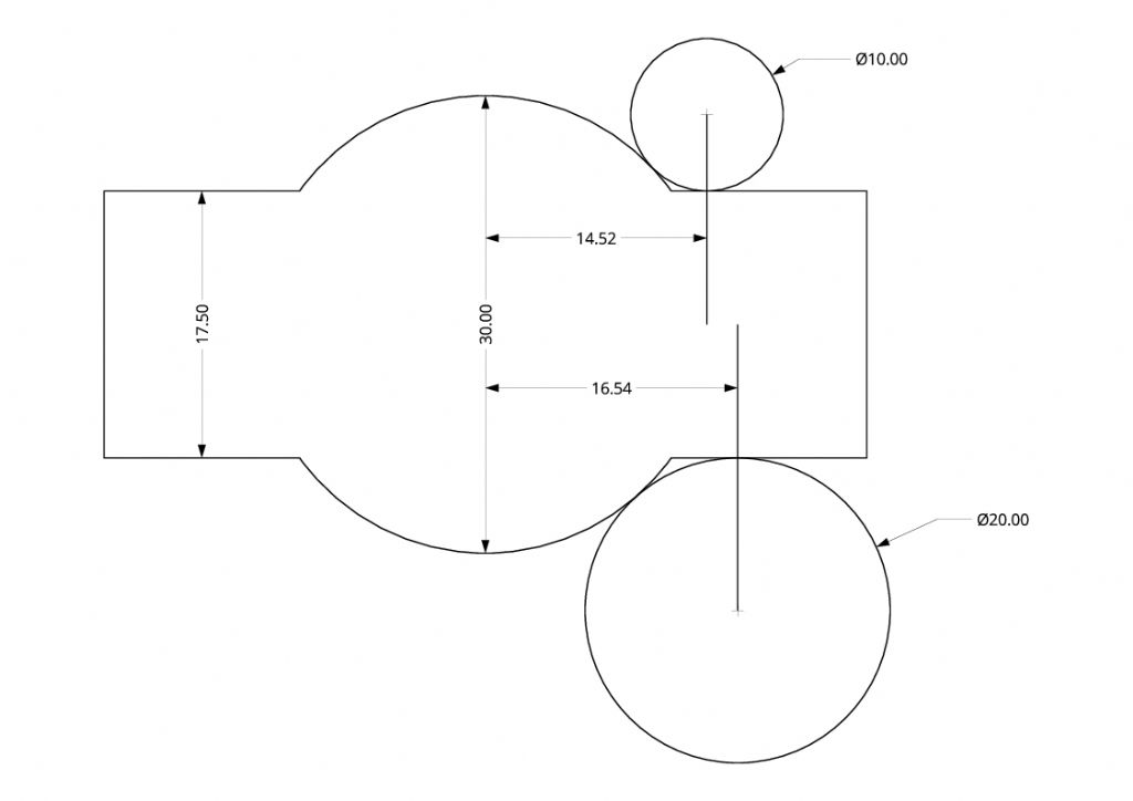
                      Tha drawing has a 10mm rad hole but the text refers to a 10mm dia hole. Either way will not effect the shape of the outside.

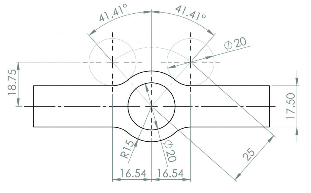
                      A CAD drawing for layouts like this is much easier than trying to calculate dimensions and angles. If machining this on a roatary table, knowing the angle to start and stop is also an advantage.

                      Paul.

                      gear selector.jpg

                      Edited By Paul Lousick on 08/08/2021 14:53:22

                      #557563
                      Colin Heseltine
                      Participant
                        @colinheseltine48622

                        Paul,

                        Thank you so much for that CAD drawing. The guy who wants this lever has just given me a hand drawn schematic with dimensions. I do have a CAD package but it is 12 months since started to learn it and last used it and I think it would have taken me all day to draw up that lovely drawing of yours. The stop and start angles will help considerably. I have just taken a look at the graduations on my large 10" Parkinson rotary table and see whether I can get to that level of accuracy, and it looks as though I can. Quick question> Is that 41 degrees 41 minutes or 41.41 (decimal parts of degree). One turn of the handle gives 5 degrees of movement, and each degree is split into 10ths. The graduations are large enough to split into 4 by eye if required. I do have a 6" stepper driven rotary table but have never tried to mill whilst the stepper is driving it.

                        Thank you,

                        Colin

                        #557576
                        DC31k
                        Participant
                          @dc31k

                          His drawing shows decimal degrees, so the angle is a little under 41 1/2 degrees. You can check it by doing inverse cosine of 18.75/25 .

                          The reason for writing is to suggest you think a little about your machining strategy. If you are driving along the straight bit towards your stopping point, as soon as you hit that point, the amount of cutter circumference engaged in the work increases drastically. At the very least, the finish on the part will be inconsistent.

                          It may be better to plunge cut the four tangent holes (perhaps with a 3/8" cutter) so the bulk of the material is removed before you drive into the corner.

                          #557608
                          Colin Heseltine
                          Participant
                            @colinheseltine48622

                            DC31k,

                            Thank you for confirming that. I obviously need to build up my knowledge of these various formulae.

                            I had planned to plunge cut the end points first but take your point of using a smaller cutter initially. Will revise my machining sequence notes.

                            Thank You,

                            Colin

                            #557618
                            Paul Lousick
                            Participant
                              @paullousick59116

                              When rotating the job on a rotary table, cut in a conventional milling direction (against the work) and not climb milling because the cutter will pull the work and rotate the table, making the cutter dig in to take up any back-lash in the gears. Not only cause a rough finish but can also damage the gear teeth. (smashed the worm wheel on my RT by doing this)

                              Paul

                            Viewing 13 posts - 1 through 13 (of 13 total)
                            • Please log in to reply to this topic. Registering is free and easy using the links on the menu at the top of this page.

                            Advert

                            Latest Replies

                            Home Forums Workshop Techniques Topics

                            Viewing 25 topics - 1 through 25 (of 25 total)
                            Viewing 25 topics - 1 through 25 (of 25 total)

                            View full reply list.

                            Advert

                            Newsletter Sign-up