Offset turning between centres

Advert

Offset turning between centres

Home Forums Workshop Techniques Offset turning between centres

Viewing 12 posts - 1 through 12 (of 12 total)
  • Author
    Posts
  • #269150
    PaulR
    Participant
      @paulr

      A simple stationary engine I'm looking at building calls for the crank to be turned by centre punching off-centre holes on the end of the bar, then mounting between centres using these holes. What the best way to ensure the holes are made in the same relative position?

      I hope I've explained that ok, but here's a picture of one end of the bar, the hole needs to be in the same place on the other end.

      https://s18.postimg.org/goe3ri1h5/Screenshot_at_2016_11_30_13_21_09.png

      I can thing of scribing lengthwise and joining up the lines across the end but doesn't feel accurate. I can scribe one end in the lathe but of course when I turn it round the bar can rotate. I don't have a mill.

      PS I know how to make it using built-up construction but would like the challenge of trying to turn it!

      Advert
      #15892
      PaulR
      Participant
        @paulr

        How to mark/punch the centres accurately?

        #269157
        Emgee
        Participant
          @emgee

          Mount the stock rod into a VEE block and place on a truly flat surface longer than the rod, that will allow you scribe at each end at the same height with both marks on the same axis. If you then turn the assembly through 90 degrees and adjust your height marking gear (vernier or other) to centre height you can mark the centre at each end, adjust to the 2nd dimension you need to centre pop and mark the rod end.

          Emgee


          Another typo edited.

          Edited By Emgee on 30/11/2016 13:42:16

          Edited By Emgee on 30/11/2016 13:47:42

          #269161
          Michael Gilligan
          Participant
            @michaelgilligan61133

            Emgee's method is fine: But if you don't happen to have the vee block and table, something similar could be done by holding the bar in the lathe toolpost and using the lathe bed as your surface plate.

            MichaelG.

            #269180
            JasonB
            Moderator
              @jasonb

              If you have a vertical slide that can also be used. Clamp the bar to the vertical slide and indicate the end true to lathe axis, centre drill shaft hole and then use vertical siide for crank pin hole. Leave work clamped to vertical slide but turn it 180degrees so other end is now facing the headstock and repeat drilling. This can be more accurate depending on your marking and punching abilities.

              #269191
              Ajohnw
              Participant
                @ajohnw51620

                How big is the offset from centre ?

                John

                #269197
                PaulR
                Participant
                  @paulr

                  Thanks for the replies. I don't have a vee block at the minute but might have by the time I come to attempt this. However, even if I do, won't the clamps stop me from rotating the whole thing through 90 degrees? I suppose I could turn the part from square bar – scribe a centre line across the ends, rotate the bar, repeat then scribe for the crank centres. But that assumes the bar is actually square if the best result is required (I've never checked this but I'm sure it would be good enough accuracy for a crank). In reality I find scribing with my height gauge rather weak and not deep enough to feel the scribed line with the punch.

                  I don't think the bar will fit in the tool-post so that's probably out of the question.

                  @Jason: I have a non-swivelling vertical side but the slots on the saddle run in the opposite direction to yours but might be ok for drilling with a light touch. I'd envisaged using a faceplate with centre and dog but now realise there'd be no easy way to face off the excess from the chuck end once the main turning was finished. What's actually in the chuck in your second picture? The cable tie/drive pin is a neat idea!

                  #269199
                  PaulR
                  Participant
                    @paulr

                    John, haven't got the plan in front of me but the webs (I think thats what the widest bits are called?) are about 1" dia and the cranks are offset about 3/4 of the radius – so maybe 3/8". That said I was thinking about scaling it up 1.5x…

                    #269200
                    Emgee
                    Participant
                      @emgee

                      Hi Paul

                      You will need to add a couple of packing pieces (parallels) each side of the clamp for the Vee block to sit on when turning the assembly through 90 degrees.

                      Emgee

                      #269209
                      JasonB
                      Moderator
                        @jasonb

                        Paul my vertical slid eis not a swivel, just mount it one way round and then unblot and remount it facing the other way.

                        You could rest the round bar on some packing then use two clamps from above in your two vertical slots, once clamped remove the packing.

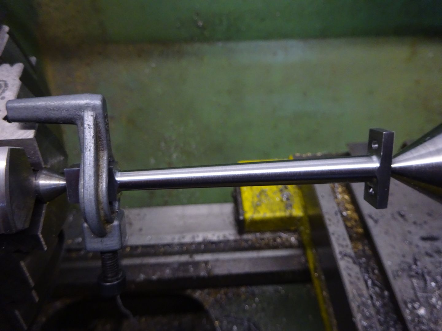
                        Most of teh time when turning between centres I tend to use a soft centre, this can just be a scrap end of steel rod, put it in teh 3 jaw and set teh topslide over and machine a 60degree included angle on the end so it is pointed like a MT or tailstock centre. Recut the taper each time you use it as it may not go back into the chuck dead true. You can then use this to support the work. I have a slight shoulder on mine so it won't slip back into the jaws from tailstock pressure but not really needed.

                        A small crank legged dog can rest against one of teh chuck jaws to drive the work. The zip tie stops any knocking on the interupted cuts.


                        What is the engine?

                        Edited By JasonB on 30/11/2016 19:15:22

                        #269214
                        Ajohnw
                        Participant
                          @ajohnw51620

                          I don't think I would do it the way the instructions suggest because when finished it needs to be parallel to the shafts that will be turned later.

                          So I'd centre drill each end of the bar stock on centre and then skim the od true between centres. These centres will be needed when the shafts at each end are turned.

                          Then mount that true in a 4 jaw and offset the bar by what ever amount is needed. You'll need to tap it parallel to the bed on 2 axis but if your 4 jaw is any good that shouldn't be a problem. The offset can be measured with a dti using the cross slide calibration to actually measure it. Strictly speaking DTI's aren't measuring instruments. You'd need 2 DTI's one to check the top is parallel and another to check the side and the offset.

                          Then turn the what ever the engine people call it. Then machine the shafts between centres. Some people add something to stiffen up the weak spot formed by the offset part. Maybe loctite or super glue a short length of bar in.

                          I believe one if the intentions of these was to turn cranks on a face plate. If well made there will only be a need to measure the offset,

                          **LINK**

                          I'd still do the initial centre drill each end and skim between centres. That way the accuracy of the above can be checked as well. If your lathe turns a taper or what ever include that in the check. Might be your best option and at this price scarcely worth thinking about castings and making one.

                          John

                          #269215
                          PaulR
                          Participant
                            @paulr

                            Thanks Jason. A soft centre with a shoulder is the first thing I turned on this lathe because the three dead centres that came with it were in poor nick (would a tool touch these hardened centres, rather than throw them away?) …

                            img_20161130_192312159.jpg

                            Odd, looks like there's a pip on the end but just a trick of the light!

                            Anyway, I'll give it a go with the slide. The engine is this one (but I won't be using any ali) https://www.youtube.com/watch?v=tiOldErjsoI I think there's a build diary on HMEM or MEM but I prefer to discover things for myself

                          Viewing 12 posts - 1 through 12 (of 12 total)
                          • Please log in to reply to this topic. Registering is free and easy using the links on the menu at the top of this page.

                          Advert

                          Latest Replies

                          Home Forums Workshop Techniques Topics

                          Viewing 25 topics - 1 through 25 (of 25 total)
                          Viewing 25 topics - 1 through 25 (of 25 total)

                          View full reply list.

                          Advert

                          Newsletter Sign-up