Worm and Worm Gear Design and Manufacture

Advert

Worm and Worm Gear Design and Manufacture

Home Forums Workshop Techniques Worm and Worm Gear Design and Manufacture

Viewing 25 posts - 1 through 25 (of 42 total)
  • Author
    Posts
  • #130250
    Anonymous

      Rather than clutter up the 'What did you do today?' thread I've started this thread to discuss the design and machining of a worm and worm gear for the steering gear on a 4" scale traction engine.

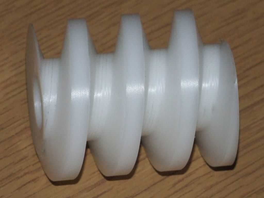
      The drawings call for a 2 start worm with a pitch of 1/2" and an OD of 1.48", plus a quoted lead angle. There is no detail about the thread form, depth or anything else, and the lead angle quoted is wrong. The thread form is diagrammatically shown as Acme, which seems reasonable. My lathe will cut 2tpi, but not the 1tpi as required for the two starts. That left me with two choices for cutting the worm. One, use the vertical mill and a series of ever smaller cutters while driving the dividing head from the table to get the helix. Two, use the vertical head on the horizontal mill with an involute style cutter to cut the thread in one pass, again driving the dividing head from the table. I don't have the requisite 'involute' cutter, so step by step it is. In which case I might as well do it on the CNC mill, as it's less effort. My CAM program can only do 4th axis toolpaths parallel to the rotary axis, or round and round it. Neither is satisfactory; the ideal would be to follow the helix of the worm. So I hand wrote my own G-code, which turned out to be quite simple, just a series of G01 moves with arguments in X and A. At this juncture it was pointed out that a 2-start worm is wrong, as the front wheels will back drive the worm gear assembly. sad So I re-designed the worm as a single start. I could have cut this on the lathe, but since I was so advanced with the G-code I decided to stick with the CNC mill. I won't go into the details of the thread form, but I did change the included angle of the Acme form to 30°, rather than the more common 29°, as I could buy a 30° tapered endmill. The basic code and methodology seems to work well, the next task is to cut the worms in steel, rather than plastic like this:

      plastic worm.jpg

      I'll also get the hand correct, the worm is supposed to be RH, but the plastic demo is LH.

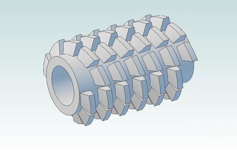
      For the worm wheel the drawings show what is essentially a helical gear. Since the pitch of the worm is rational the DP of the mating worm wheel is irrational, so involute cutters will not be available. Furthermore I wanted a single enveloping worm wheel, not a helical gear. The obvious way to make this is by free hobbing, ie, the hob drives the worm gear as it is cut. I've spent a lot of time looking at hob design and drawing various styles of hob, like this:

      worm gear wheel hob.jpg

      However, I've decided that it is just too involved to make a hob with the proper form relief. I also looked at machining the worm wheel direct on the CNC mill. However, the tooth form required is very complex, and I miserably failed to draw even a rough approximation. So back to free hobbing it is. For the hob I am going to essentially machine a worm in silver steel, which can be gashed to provide some measure of relief, and then hardened and tempered. I intend to add extensions to the hob so that one end will fit into a Clarkson Autolock chuck and the other end can be supported by a centre.

      As I make progress I'll update this thread.

      Regards,

      Andrew

      Advert
      #15661
      Anonymous
        #130253
        Sub Mandrel
        Participant
          @submandrel

          Hi Andrew,

          I wouldn't worry about not having form relief on the hob for a one off. Gash the gear first and take it all very slowly. It's worked for me on two gears.

          In 1966 P Holden cut a 7 3/4" worm wheel using a home made hob without form relief from a pulley casting that he gashed. (guess who's been reading old MEs this morning).

          Neil

          #130256
          Michael Gilligan
          Participant
            @michaelgilligan61133

            Very useful topic, Andrew

            I shall be following it with interest.

            … Nothing to contribute as yet; but lots to learn.

            MichaelG.

            #130261
            John Stevenson 1
            Participant
              @johnstevenson1

              Why write the code ?

              What's wrong with

              G20. ( imperial units )

              G01 X2.0 A1440 F5.0 ( linear move 2" whilst A revolves 4 times )

              Catch up later, off down Swaliland to collect a machine

              #130266
              blowlamp
              Participant
                @blowlamp

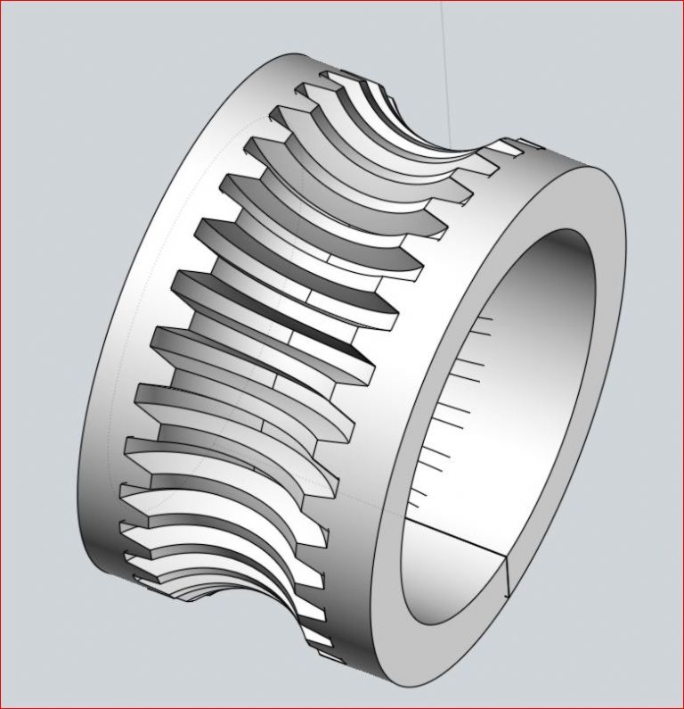
                I managed to get a fair approximation of a worm wheel in MoI.

                Martin.

                capture.jpg

                #130293
                Anonymous

                  Neil: My worm wheel will be 22 teeth with a DP of 6.283, so quite coarse teeth. Rather than relieve the teeth properly I intend to gash them such that the remaining teeth look like triangles. Thus the relief is obtained by removing most of the teeth. The hob only has to cut two gears, so it's unlikely it'll ever need to be sharpened.

                  JohnS: If I don't write code what am I going to run? wink I've written almost exactly what you posted, except that I use metric, so:

                  G21

                  blah blah blah tool change/spindle speed/coolant/rapid to start

                  G01 X76.2 A2160.0 F320.0 (3" and 6 turns)

                  Martin: How the xxxx did you do that? Extrude an involute tooth form at the lead angle around the PCD of the worm? I tried that and the result looked nice, but assembled with the worm the tooth shape was clearly wrong and didn't mesh properly. That's when I gave up trying to model the worm wheel teeth.

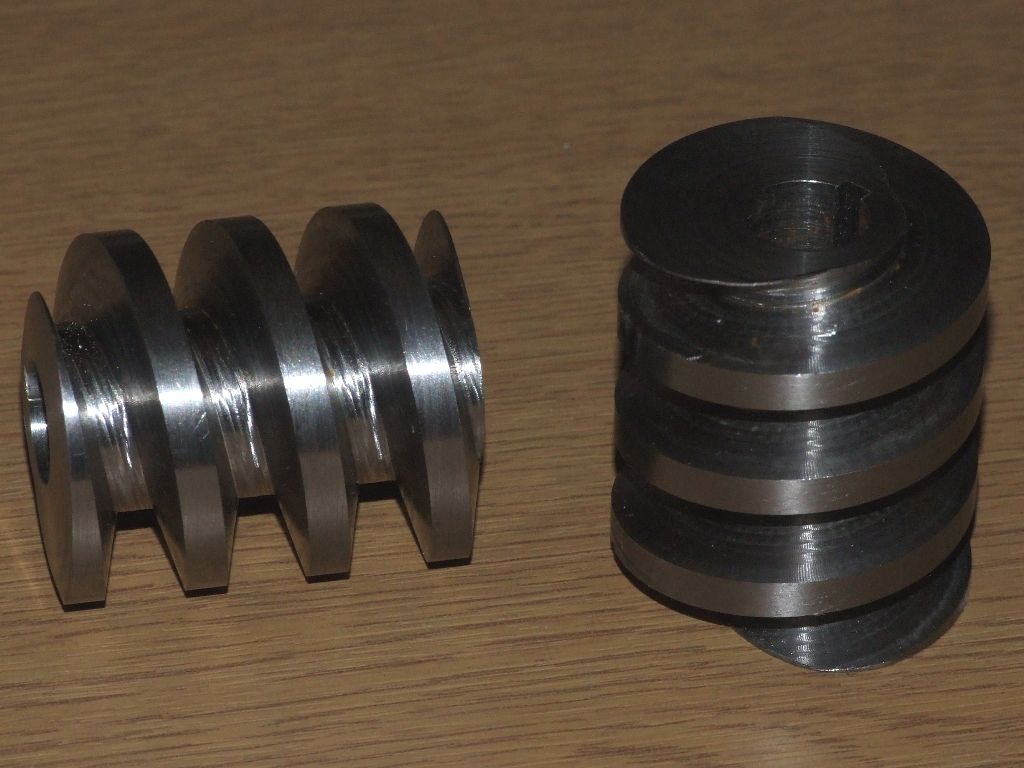
                  Here are two worms I've made in steel this evening, RH this time:

                  steel worms 1.jpg

                  I'm not at all happy with them. sad It's all down to feedrates. I used three cutters; 6mm carbide at 4000rpm and feedrate of 420mm/min, 3mm carbide at 5000rpm and feedrate of 320mm/min and a HSS taper end mill at 1500rpm and 120mm/min. I thought that the rotary table didn't seem to be slowing down much on the slower feedrates. In fact it wasn't, I think it was flat out all the time. I'm amazed I haven't badgered at least one of the cutters.

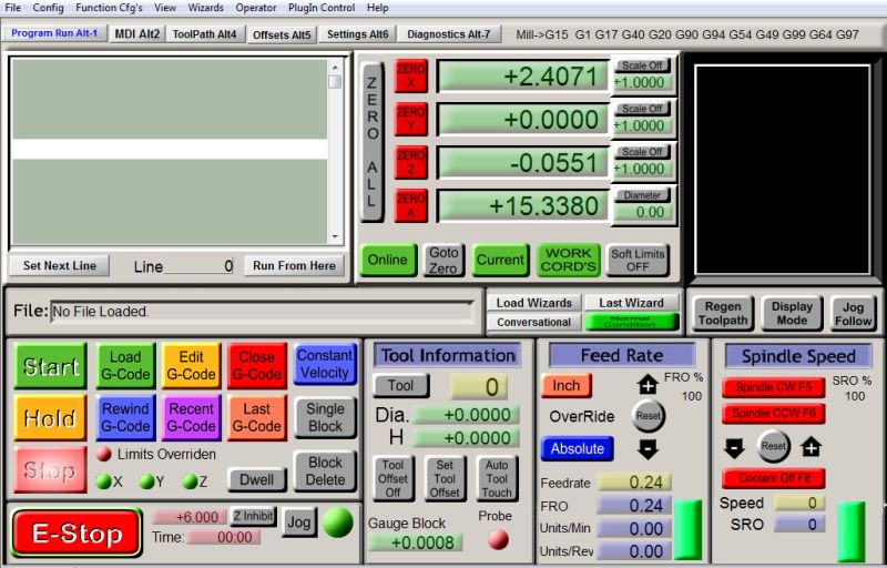
                  Clearly I haven't got to grips with linear/rotary combined feedrates. I understand that if a linear motion and rotary motion are combined in G01 then the feedrate is taken as an 'unwrapped' linear rate, according to a rotation diameter correction factor. Here is where it all gets murky. Both the Mach3 and my mill manual talk about a rotation axis diameter correction, but on the screen it is shown as a radius correction. And does the computation take into account the number of turns the rotary axis makes? I set 16, thinking 16mm radius, but who knows how it is interpreted.

                  Needless to say neither manual actually gives any examples, or talks about units. I wonder if Mach3 only understands imperial for the correction factor? Certainly when setting the tool table the differential heights are shown in millimetres when taking measurements, but they're stored in the tool table in inches irrespective of G20 or G21.

                  I'm going to have to do some experiments by typing code into the MDI and timing the rotation of the rotary table.

                  Regards,

                  Andrew

                  #130299
                  John Stevenson 1
                  Participant
                    @johnstevenson1

                    Andrew,

                    My screens show diameter on both screens ?

                    #130333
                    Anonymous

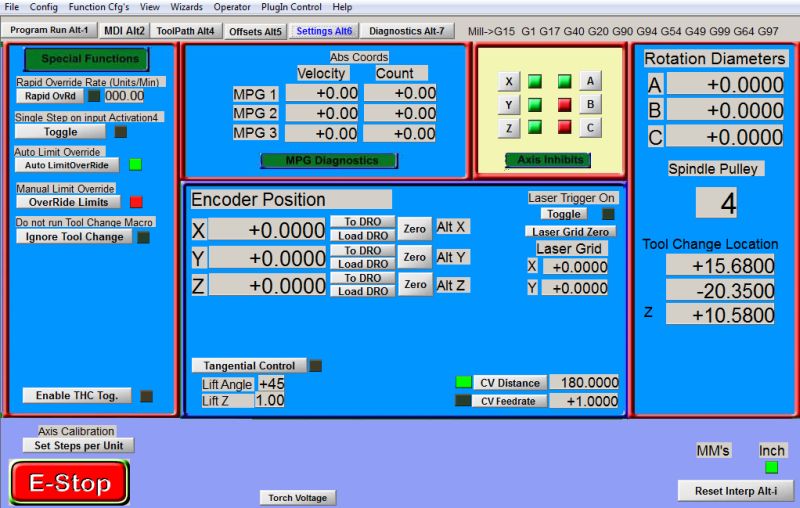
                      JohnS: I'm using a Tormach CNC mill, which uses their own customised version of Mach3, so my screens are different to yours. However, you are correct, there are two places to enter the correction; on the main control screen, and on the settings page. Confusingly on the settings page it's listed as a correction diameter, on the main page as a radius.

                      I've done a few tests this morning to try and understand the feedrates. For G01 commands with an argument only for A and F it all works perfectly. The machine interprets the F in degrees/sec, and the movement of the table is spot on, according to the secondhand on my watch. However, when we introduce an argument for X as well, where the interpretation of F is supposed to be mm/min it all goes to pot. With the correction diameter set at 31.8mm, so that the circumference is about 100mm, the following code:

                      G01 X0.1 A360.0 F100.0

                      takes 3 minutes and 35 seconds. It ought to take 1 minute according to my logic. If I reduce the correction diameter to 15.9mm, half the diameter so for the same feedrate the table ought to turn twice as fast the code takes 3 minutes.

                      I tried everything in inches as well, and that didn't work either. If I use a correction diameter of 31.8mm and a feedrate of 358 then the rotary table does one turn in a minute.

                      The whole thing makes no sense at all to me; for a given feedrate the rotation speed is not directly proportional to the correction diameter, which it should be.

                      Regards,

                      Andrew

                      #130341
                      blowlamp
                      Participant
                        @blowlamp

                        Have you seen/tried this?

                        **LINK**

                        Martin.

                        #130345
                        Anonymous

                          Martin: Thanks for the link. My rotary table has no problem with speed, it's getting a consistent feedrate when milling in both X and A that seems to be the issue.

                          However, after some more searching and fiddling I think I have the solutuion. First, there is an error in the Tormach version of Mach3, in that the correction diameter/radius is inconsistently labelled on the screens. Apparently the correction diameter is a red herring, it's actually the distance from Z=0 to the rotation axis. For my worm Z=0 is the rotation axis, but if you set zero you disable the correction function. So I set it at 0.0001, which enables it. Then, with Z=15.9mm, ie, a diameter of 31.8mm and a circumference of 100mm I did the following:

                          G01 X0.1 A360 F100

                          This actually took a shade over 30 seconds, instead of 60 seconds, but at least it's consistent. If you double the rotation degrees, or halve the feedrate, or double the Z value, then the time exactly doubles, as it should.

                          So it seems that Mach3 does the correction from the actual Z value of the cutter. But you have to set the correction diameter to a non-zero value to enable it, and for some reason the actual feedrate is twice that demanded. Presumably this is due to a foul up regarding radius versus diameter. At least the numbers and feedrate are now consistent, and scale as they should.

                          The next thing is to re-run my worm G-code and time the rotations to see that the feedrates are actually changing as I expect.

                          Regards,

                          Andrew

                          #130353
                          John Stevenson 1
                          Participant
                            @johnstevenson1

                            Andrew also ran some tests but didn't get what you got then realised I awyays zero on top of the work.

                            Find it safer that way, it it goes to Z zero it only kisses the work and doesn't try to buty itself 10" into the part.

                            However now found that the settings on the settins page are for RADIUS, not diameter. So need to get these pages and screens altered.

                            Thanks for that.

                            #130520
                            Anonymous

                              The plot thickens; in order to test my understanding of the feedrates I ran some more tests last night. As before I used the following code, all distances in millimetres:

                              G01 X1.0 A360.0 F50.0

                              With the radius correction set to 0.0001 and Z=15.9, the code took 1:03 minutes, pretty close to the desired 100mm/min feedrate. So far so good. It is always interesting to explore the limits, so next I tried the same code with Z=0.1, ie, not a lot! The code took 18 seconds to run. In essence the rotary table is running as fast as it can in an attempt to achieve the required feedrate. Again, pretty much as expected. Then I tried the code with Z=159, the code took 3:57 minutes, not what was expected, it should take about 10 minutes. What's going on? What else did I change? Due to the way my tool table is set up I had to change tools in Mach3 to get Z=159 without hitting the limit switches. Previous tests had been done with tool 0, ie, my master tool. For this test I selected tool 1. So it looks like the linear/rotary feedrate correction doesn't follow the changes in Z due to different tool lengths? If that's the case, then it's about as much use as a chocolate teapot. sad

                              After that debacle I did one more test, with tool 0 selected. This time the code was:

                              G01 X200.0 A360.0 F50.0

                              In other words quite a slow helix. The code took 4:20 minutes, which is about double what I would have expected.

                              Regards,

                              Andrew

                              #130720
                              Anonymous

                                I emailed the manufacturer of my CNC mill and got a reply back saying that they thought that the correction radius 'feature' in Mach3 was a bit of a hack. However, they're going to look into the issues and possibly add it to the bug list. They also suggested using G93, inverse time feedrate.

                                My CNC handbook, aimed at the professional user, simply says that inverse time feedrate is seldom used and will not be discussed further. sad It is a slightly odd way of looking at feedrate. The value of the F argument is the inverse of the time to be taken to execute the command, in minutes. For example:

                                G01 X100.0 F2.0

                                will move X 100mm in half a minute, whereas:

                                G01 X100.0 F0.5

                                will move X 100mm in two minutes. While F is normally modal, it isn't when using G93, so every G01, G02 or G03 command has to have a corresponding F value.

                                I had already tried G93, and reached the conclusion that it didn't work. However, I gave it another go, and it now works fine, so it must have been finger trouble on my part. This evening I re-wrote the G-code for the worm using inverse time feedrates, based on the linear cutting speed I wanted to achieve and the length of the helix over which the tool was travelling. I also dry ran the code and timed the various execution times using the lap timer on my mobile 'phone. The times are all about 5% longer than I would expect, but are very consistent from line to line, less than a second variation.

                                I've made some new blanks for the worms, so the next step is to double check the feedrates and then cut another worm in steel.

                                Regards,

                                Andrew

                                #130858
                                Anonymous

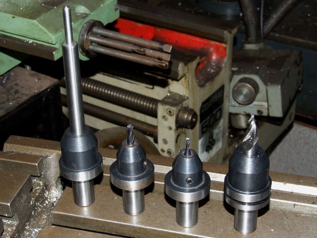
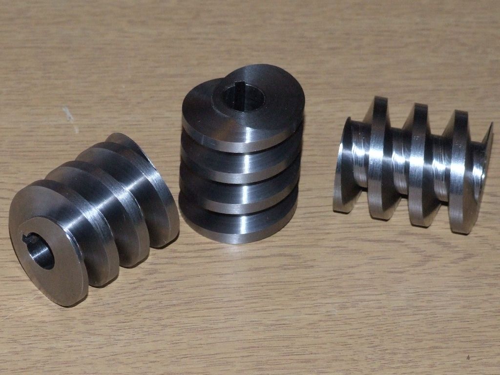
                                  The final worms are made! Like a lot of operations, once everything is sorted out the actual machining is a bit of an anti-climax. However, it is strangely mesmeric to watch the rotary table turn and a helix magically appear in the blank. Here are the tools used; from left to right, the master tool used to set zero and relative tool lengths, a 6mm cutter for initial roughing, a 3mm cutter for deeper roughing and a 30° included taper end mill for finishing:

                                  worm tools.jpg

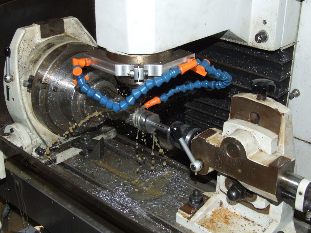
                                  The general set up:

                                  worm setup.jpg

                                  And the final worms:

                                  final worms.jpg

                                  Why three worms? Because I'm making two engines, but I made three blanks just in case of a boo-boo in the machining.

                                  Regards,

                                  Andrew

                                  #130860
                                  Michael Gilligan
                                  Participant
                                    @michaelgilligan61133

                                    Nicely done !

                                    MichaelG.

                                    #130868
                                    Muzzer
                                    Participant
                                      @muzzer

                                      Predictably perfect product!

                                      BTW, what's the material of the worms and the wormwheels? Is wear an issue if you use steel? Obviously they will be well greased.

                                      #130894
                                      Anonymous

                                        The worms are in steel, almost certainly EN1A. The worm wheels will be cast iron, although I plan to make a prototype in something else, probably aluminium, before trying the actual castings.

                                        I don't think wear will be a problem, the steering is not a precision mechanism. During my only experience of driving a full size traction engine I nearly demolished the school tennis court fence, as the steering needed two turns of the wheel before anything happened. And then I discovered that I was turning it the wrong way.

                                        Regards,

                                        Andrew

                                        #131112
                                        Anonymous

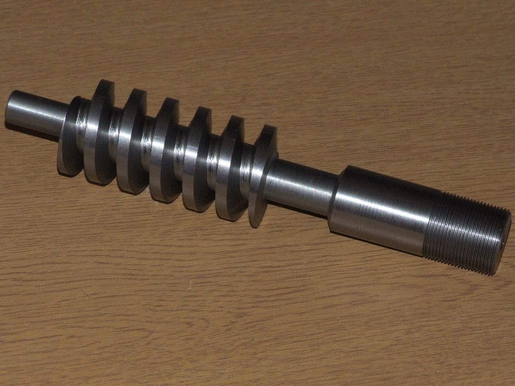
                                          More progress; here's the embryo hob, in silver steel:

                                          embryo_hob_1.jpg

                                          Next job is to gash it and then harden it. Before I do that though I need to decide how many gashes (current thinking is 7) and make sure I have the direction correct. The hob will fit into a SKF Fastloc (Clarkson Autolock lookalike), so I need to make sure that the cutting forces tend to tighten the cutter into the chuck.

                                          Regards,

                                          Andrew

                                          #131869
                                          Anonymous

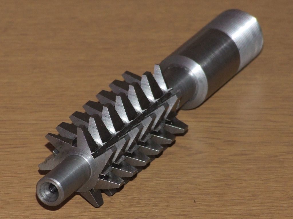
                                            The hob is now gashed. I settled on 7 teeth, so there is no common factor between the number of teeth on the hob and in the worm gear (22 teeth). Given the width of the worm gear blank it also ensures that each following tooth always engages with the gear blank before the preceding tooth exits the gear blank. Having said that, the teeth look a little weak to me; time will tell!

                                            worm gear cutter.jpg

                                            Some work with a file is needed to clean up the teeth, and add some relief, before hardening.

                                            Regards,

                                            Andrew

                                            #131947
                                            Sub Mandrel
                                            Participant
                                              @submandrel

                                              > no common factor

                                              Aside from a popular approximation for PI

                                              I always think it's a shame to harden cutters when they look as nice as that! I did worry about insufficient engagement to rotate the blank, but as you say you will have multiple teeth engaged you should be OK as long as you gash the blank deeply enough (I failed to do this once and hobbed a 61-tooth gear for a dividing head).

                                              Edit: thinking about it when the hob first contacts the blank, it's 'natural pitch' will want to cut two extra teeth at the OD than it will cut when advanced to the PCD. Perhaps a way around this is to have the hob fully advanced from the start and make the cut from the side of the blank rather than in from the edge. That way the hob's PCD will remain constant at the required value. Does that make sense?

                                              Neil

                                              Edited By Stub Mandrel on 07/10/2013 16:01:17

                                              #131964
                                              Muzzer
                                              Participant
                                                @muzzer

                                                I don't know if your camera does video but it would be fascinating to see this hobbing in action. I think I have an idea how it should work but it seems to me there could be some rubber pants moments!

                                                Merry

                                                #131983
                                                Anonymous

                                                  Muzzer: Yes, my camera does have video mode, although whether I have time to video the first attempt is a different matter. Forget analogue, machining is digital! There are no half measures; it's going to be a case of set everything up the way I think it should be, and then drop the clutch and stand back. It'll either work or disintegrate in short order. The horizontal mill won't care either way. A 5hp motor geared down to 50 rpm will just spit out the bits if I get it wrong.

                                                  Stub: I understand the idea of having the hob at full depth and moving it across the blank, but I assume that will generate what is essentially a helical gear? I am aiming for a single enveloping worm wheel rather than a helical gear. Machining a helical gear is pretty straightforward, so I thought I'd have a go at a 'proper' worm wheel instead. The plan is to gash the wheel beforehand. The books say to use an involute cutter of the appropriate DP and number of teeth and of similar diameter to the worm. Since the linear pitch of the worm is rational the DP of the worm wheel is irrational, in fact it is 6.283 etc. I happen to have a 6DP involute cutter for 21-25 teeth which is pretty close. However it is quite a bit bigger diameter than the worm, so I won't be able to get full depth. I'm not sure what effect this will have. I could try and make a special involute cutter as well, but I'm tempted to just give it a go and see what happens.

                                                  Regards,

                                                  Andrew

                                                  #132056
                                                  Mark C
                                                  Participant
                                                    @markc

                                                    Andrew, following Martins picture I thought I would see how hard it was to draw in SolidWorks, it turns out it was quite easy – simply draw the wheel blank, sweep cut the rack form along a suitable helix and then copy the cut around the wheel.


                                                    Mark

                                                    PS. This is drawn at arround the scale you need – 20 t 1/2" pitchworm wheel.jpg

                                                    Edited By Mark C on 08/10/2013 17:48:14

                                                    #132065
                                                    Bazyle
                                                    Participant
                                                      @bazyle

                                                      Andrew, is there a simple explanation of why this rational irrational aspect is so?

                                                      Mark, you make that drawing sound so easy. Either you or the program is very impressive.

                                                    Viewing 25 posts - 1 through 25 (of 42 total)
                                                    • Please log in to reply to this topic. Registering is free and easy using the links on the menu at the top of this page.

                                                    Advert

                                                    Latest Replies

                                                    Home Forums Workshop Techniques Topics

                                                    Viewing 25 topics - 1 through 25 (of 25 total)
                                                    Viewing 25 topics - 1 through 25 (of 25 total)

                                                    View full reply list.

                                                    Advert

                                                    Newsletter Sign-up