Centreing a rotery table

Advert

Centreing a rotery table

Home Forums Workshop Techniques Centreing a rotery table

Viewing 25 posts - 1 through 25 (of 31 total)
  • Author
    Posts
  • #96191
    tony bastick
    Participant
      @tonybastick78554

      Hi all,what is the simplest way to centre a 3 jaw chuck mounted on a rotery table under a vertical milling head.Thanks Tony

      Advert
      #15588
      tony bastick
      Participant
        @tonybastick78554
        #96198
        MAC
        Participant
          @mac53652

          Hi – a tip I picked up from here was to use a ball bearing (I think the one I got is 32mm – but obviously you just get one to suit your rt/chuck/spindle). Just loosly align the table, raise table / lower quill to trap the ball bearing, clamp down and you're good to go!


          I think it's a great tip – and actually look forward now to using the rotary table .

          Edited By MAC on 11/08/2012 23:04:04

          #96200
          I.M. OUTAHERE
          Participant
            @i-m-outahere

            Hi Tony .

            The important thing really is to ensure that the piece you want to machine is running true in the chuck as you can use a wiggler / centre finder to find the centre using the X&Yco-ordinates .

            I will run through how i set up my table from scratch but some may have a quicker way .

            I have turned a mandrel that is round and parrallel with a 2mt taper on one end as this fits my rotary table and the other end has a large centre that is also tapped 8×1.25 mm so i can slide a tube over the end then fit a large washer and screw in a bolt to extract the mandrel from the taper without moving the roary table and the mandrel is long enough to protrude from the chuck by 25mm.

            I fit the mandrel to the rotary table and clock it with a DTI to ensure it runs dead true then i carefully fit the chuck over this mandrel , gently tighten the jaws and nip up the clamp bolts for the chuck .

            I then re – check the mandrel is running true and if it is all good i fully tighten the clamp bolts.

            I fit a dead centre in the mill spindle and roughly locate the rotary table where i want it on the mill .

            Then i simply locate the dead centre into the centre in the end of the mandrel and as i do the whole lot of this operation with the worm disengaged i give it a turn to ensure the centre is seated.

            I then lock the spindle of the mill (z axis) and fit and tighten the clamps for the rotary table , i also lock the mill table and zero my X&Y readouts/dials.

            If youre chuck is already mounted to the rotary table and running true you could mount up a piece of round bar (silver steel or something that has been turned round and parrallel ) in a collet in the spindle and then clamp this in the chuck to locate the rotary table but this will not indicate the runout of your chuck .

            IAN

            #96208
            doubletop
            Participant
              @doubletop
              Posted by MAC on 11/08/2012 23:03:19:

              Hi – a tip I picked up from here was to use a ball bearing (I think the one I got is 32mm – but obviously you just get one to suit your rt/chuck/spindle). Just loosly align the table, raise table / lower quill to trap the ball bearing, clamp down and you're good to go!

              I think it's a great tip – and actually look forward now to using the rotary table .

              Edited By MAC on 11/08/2012 23:04:04

              Now I know why I've got a big ball bearing in the stuff my dad gave me. Always wondered what he had used it for, I'll give it a go.

              Pete

              #96210
              Stewart Hart
              Participant
                @stewarthart90345

                Not quite with it regarding the ball bearing, if its not to forward a ? where do you put the bearing, do you grip it in the chuck so that when you lower the spindle it square up in its bore.

                What i do is put a centre into the job or a bit of scrap whilst its chuked in the lathe, then keeping it in the chuck transfer the chcuk over to the RT and with a running centre in the mill spindle locate it in the centred part this pulls everything true and clamp down.

                Stew

                #96211
                blowlamp
                Participant
                  @blowlamp

                  Do you want to centre it to the rotary table or to the milling machine spindle?

                  Martin.

                  #96212
                  MICHAEL WILLIAMS
                  Participant
                    @michaelwilliams41215

                    Stewart :

                    Bearing ball not ball bearing . This is a fairly standard way of aligning two hollow shafts end on and is accurate to within a few thou if done carefully . Very prone to errors from chamfers and burring over though .

                    The only truly accurate method on a manual machine is to use a turn round method with a dial gauge .

                    Regards ,

                    Michael Williams .

                    #96213
                    tony bastick
                    Participant
                      @tonybastick78554

                      Hi all, thanks for all your tips, I now can choose a quick set up for a less acurate job or take a bit more time to get it spot on .Thanks again its easy when you know how.

                      #96216
                      doubletop
                      Participant
                        @doubletop

                        I've never been happy that my chuck is truly centered on the table so plan to give it a go and see what happens

                        1) Use the ball to centre the rotary table and quill

                        2) Hold the ball in the chuck and center the chuck to the quill, and hence the chuck to the rotary table.

                        3) Zero DRO' s for reference point

                        4) Rotate the table and clock the ball in the chuck to see if it really is centred on the table

                        5) Clock the quill to the ball to see how well that was aligned

                        Pete


                        Edited By Doubletop on 12/08/2012 10:58:35

                        #96219
                        NJH
                        Participant
                          @njh

                          A " quick, dirty ( and cheap) " method using kit you will have already. – Put MT centres in the rotary table and spindle, lower the quill to trap a 6 inch rule betwwen the points of the centres and adjust X & Y travel such that the rule is level in both directions.

                          N

                          P.S The "Dirty" refers to lack of precision compared to a dial guage method.

                          Edited By NJH on 12/08/2012 11:18:47

                          #96220
                          Ian S C
                          Participant
                            @iansc

                            I don't often use my rotary table, my method of centering it is to put a @ MT center in the table, and a piece of steel bar with a center hole in the chuck of the mill, bring thetwo centers together, and tighten the table to the mill. Then to mount the three jaw chuck center, grip the steel barthats in the mill chuck with the three jaw, and tighten that to the rotary table, seemsto work for most jobs. Ian S C

                            #96225
                            MAC
                            Participant
                              @mac53652
                              Posted by Doubletop on 12/08/2012 10:57:03:

                              I've never been happy that my chuck is truly centered on the table so plan to give it a go and see what happens

                              1) Use the ball to centre the rotary table and quill

                              2) Hold the ball in the chuck and center the chuck to the quill, and hence the chuck to the rotary table.

                              3) Zero DRO' s for reference point

                              4) Rotate the table and clock the ball in the chuck to see if it really is centred on the table

                              5) Clock the quill to the ball to see how well that was aligned

                              Pete


                              Edited By Doubletop on 12/08/2012 10:58:35


                              This is exactly what I do – except I just wind the jaws of the chuck out a little and the ball sits perfectly in the central hole.

                              It's more than accurate enough for what I do – and for what I could ever imagine machining, unless NASA give me a call one day!

                              Edited By MAC on 12/08/2012 12:54:20

                              Edited By MAC on 12/08/2012 12:54:41

                              #96233
                              Harold Hall 1
                              Participant
                                @haroldhall1

                                Make a plug to fit the hole in the rotary table and centre drill one end ensuring that the diameter and centre drilled impression are concentric. Give the plug a head so that it will not fall into through the table. Using a centre in the machine spindle lower it into the centre drilled plug and secure the rotary table and lock the X and Y axis.

                                Raise the centre, remove the plug, place the chuck on the rotary table and place the plug in the chuck and secure. Lower the machine spindle with centre into the plug and secure the chuck on the table.

                                You now have the chuck concentric with the rotary table and both with the machine spindle. The assembly can now be moved off centre to perform the task require.

                                If your table has a Morse taper than you will need two plugs though the taper one needs only to be short and perfection of fit is not necessary.

                                This is just a variation on Ian C S,s excellent method, especially if your table has a Morse taper.

                                For more detail on using a rotary table see here

                                Harold

                                #96244
                                MICHAEL WILLIAMS
                                Participant
                                  @michaelwilliams41215

                                  Different people make the valid point that simple methods of centering rotary tables work well enough and are adequate for general work .

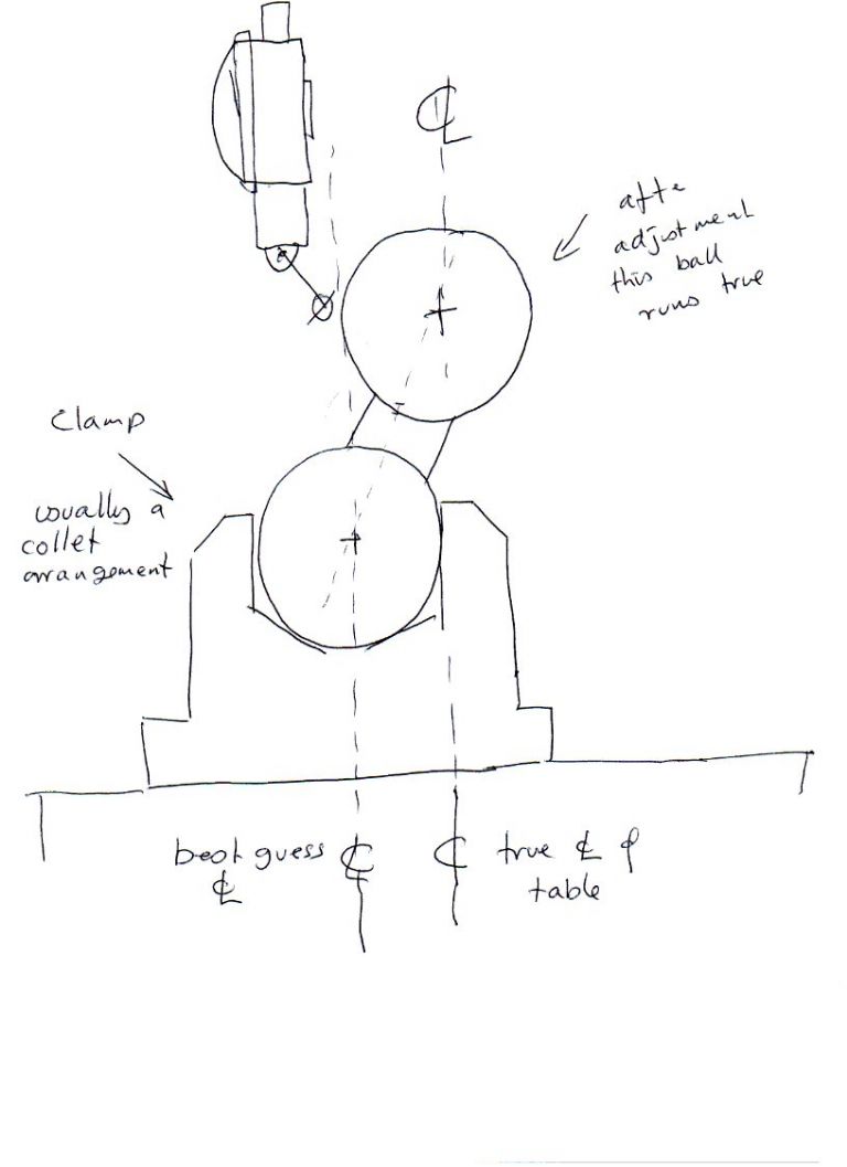
                                  Some of you however might like to try a little super precision and modern technology by making a setting ball .

                                  A setting ball consists of an accurate ball mounted on a short stem and with the stem mounted into one of several different type of base unit to suit particular applications . The stem is mounted in such a way that it can be tilted by a few degrees in all directions and then locked . Tilting the stem effectively means that the ball can be moved a little relative to the base unit C/l .

                                  In use the base unit is mounted on the table or in a chuck and centred by eye . Using a dial gauge the table is rotated and the ball nudged around until it runs true . Ball is then locked in position .

                                  You now have an absolute reference exactly on C/l of table and the whole setting takes about 20 seconds .

                                  Setting ball devices have many other applications .

                                  Michael Williams .

                                  #96247
                                  NJH
                                  Participant
                                    @njh

                                    Hi Michael

                                    I'm having a bit of trouble visualising that – how about a photograph?

                                    How too to produce an " accurate" ball and what size?

                                    N

                                    #96264
                                    doubletop
                                    Participant
                                      @doubletop

                                      I see what Michael is getting at. The adjustable "ball on a stick" doesn't make any assumptions that the centre hole in the round table is actually on centre. In an extreme example the "stick' could be mounted on the periphery of the table and the ball adjusted to be over the centre. as long as all the errors are taken out using the DTI as the table is rotated the ball has to be directly over the CL.

                                      Tonight I tried the ball I had lying around. It's about 40mm dia. It was really easy to set up the table and quill on centre and the vice on the table. Clocking the ball with it just laying in the centre hole of the chuck, not clamped in the jaws, and rotating the table gave me less tabout 1 thou variation in 360degrees. That will do me.

                                      Pete

                                      #96266
                                      MICHAEL WILLIAMS
                                      Participant
                                        @michaelwilliams41215

                                        Setting ball

                                        #96267
                                        Geoff Sheppard
                                        Participant
                                          @geoffsheppard46476

                                          If you can take time out for a 'diversionary' project, try making the elegant little device described by Peter Rawlinson in MEW 118. Held in the spindle collet, a probe rotates around a pin or a bore, but a dial gauge stays facing you. I've just completed one and its smashing!

                                          Geoff

                                          #96288
                                          NJH
                                          Participant
                                            @njh

                                            Hi Michael

                                            I guess thats pretty much like a ball and socket camera tripod head LINK then with an additional ball attached in place of the camera. Interesting but a little too refined for my humble efforts I suspect!

                                            Thanks

                                            Norman

                                            #96294
                                            Lambton
                                            Participant
                                              @lambton

                                              You do not need any aids to centre a 3 jaw chuck on a rotary table other than a DTI using the same methodology as cantering work in a 4 jaw chuck on the lathe. What I do is to fit the chuck onto the table roughly centred using the guide rings on the table and nip up the clamps. Then chuck a piece of silver steel of similar diameter to the work piece. Swing the table worm out of engagement so the table can be rotated easily and quickly. Bring the DTI up to the silver steel blank and rotate the table noting the run-out as indicated on the DTI. Tap the chuck in the appropriate direction with a soft mallet and test again. Repeat this until the chuck is truly centred and tighten the clamps. Test again. Job done.Very simple and quick to do.

                                              #96298
                                              Versaboss
                                              Participant
                                                @versaboss

                                                Wondering that nobody mentions the 'Osborne maneuver'. Does not need a DTI, only an edge finder and somethin exactly round and of known diameter, e.g. a ring from a ball bearing. called disk in the description below. For a R.T. you can use the outside; possibly even for a chuck if you don't get in conflict with the jaw slots.

                                                Shameless copy from the Practical Machinist forum:

                                                > Here's the Osborne maneuver:

                                                Measure diameter of disk carefully before starting. Put edge finder in mill.
                                                With disk mounted on mill, line up approximately at center of disk.
                                                Move off the left-hand edge, then move back and find the left edge of the disk with the edge finder.
                                                From that point, move to right a distance equal to disk radius plus edge finder radius.
                                                Move off top of disk.
                                                Move back and pick up top edge of disk with edge finder.
                                                Move down distance of disk radius plus edge finder radius.
                                                Repeat above sequence for X-Y again, and you'll be very close to the center, especially if your starting point was reasonably close to the center to begin with.
                                                You can repeat again to improve even more, but after that you probably won't gain anything. It converges pretty fast. <

                                                Greetings, Hansrudolf

                                                #96299
                                                MICHAEL WILLIAMS
                                                Participant
                                                  @michaelwilliams41215

                                                  **LINK**

                                                  About halfway down the page .

                                                  Essentially the same process works for centering a probe , a workpiece or a rotary table .

                                                  No difference in principle on CNC or manual machines with DRO .

                                                  Michael Williams .

                                                  The 'Osborne' procedure only works if the reference ring is truly centered on the table before you start .

                                                  Edited By MICHAEL WILLIAMS on 14/08/2012 11:02:44

                                                  #96354
                                                  I.M. OUTAHERE
                                                  Participant
                                                    @i-m-outahere

                                                    The 'Osborne' procedure only works if the reference ring is truly centered on the table before you start .

                                                    All the more reason to use a four jaw chuck i reckon .

                                                    I have yet to find a three jaw that runs perfectly , well one that i could afford anyhow !

                                                    The thing that annoys me is rotary tables with 3 tee slots as this makes it difficult to mount a 4 jaw chuck to it .

                                                    My local supplier does not list front mounting 4 jaw chucks either but i imagine they are availlable .

                                                    Has anyone come up with an adapter so a 4 jaw chuck can be mounted to a table with 3 tee slots ?

                                                    IAN

                                                    #96364
                                                    MICHAEL WILLIAMS
                                                    Participant
                                                      @michaelwilliams41215

                                                      Hi IAN B ,

                                                      In cases where the chuck is a good bit smaller than the rotary table a good plan is to mount the chuck on a flat bottomed backplate with a good size flange around the outside of the chuck . By making any suitable arrangement of slots and holes in the flange chuck can be bolted down to 3/4 slot tables or indeed to anything . A further advantage to having an external flange holding system is that the fixing holes/slots can be made slightly oversize allowing the chuck to be fine adjusted for position allowing any particular workpiece to be centered exactly .

                                                      Regards ,

                                                      Michael Williams .

                                                      Edited By MICHAEL WILLIAMS on 15/08/2012 09:37:37

                                                    Viewing 25 posts - 1 through 25 (of 31 total)
                                                    • Please log in to reply to this topic. Registering is free and easy using the links on the menu at the top of this page.

                                                    Advert

                                                    Latest Replies

                                                    Home Forums Workshop Techniques Topics

                                                    Viewing 25 topics - 1 through 25 (of 25 total)
                                                    Viewing 25 topics - 1 through 25 (of 25 total)

                                                    View full reply list.

                                                    Advert

                                                    Newsletter Sign-up