Rotary encoder for spindle speed

Advert

Rotary encoder for spindle speed

Home Forums Workshop Techniques Rotary encoder for spindle speed

Viewing 13 posts - 1 through 13 (of 13 total)
  • Author
    Posts
  • #86751
    DerryUK
    Participant
      @derryuk

      Following on from Tony Jeffree's article in MEW 186 I am looking for a rotary encoder to measure spindle speed. My lathe top speed is 3000 RPM.

      I am intending to use LinuxCNC software which by default requires an encoder with A=100 PPR and Z=1 PPR.

      The best new shaft driven encoder I can find on ebay (or anywhere else) is £65. A possible option would be to use a cheaper (£35) A=1000 Z=1 encoder with an external divide by 10 on the A output.

      Anyone know of another source of suitable encoders?

      Thanks,

      Derry.

      Edited By DerryUK on 07/03/2012 16:01:55

      Advert
      #15568
      DerryUK
      Participant
        @derryuk
        #86775
        Sub Mandrel
        Participant
          @submandrel

          Divide by 10 is easy if you have some basic electronic skills, just use a CMOS decade counter chip.

          Neil

          #86778
          John Haine
          Participant
            @johnhaine32865

            Hi Derry,

            At the moment I use my Super 7 with Mach 3 and a single pulse per rev sensor but since seeing the comments about EMC2 giving better threading I thought that I might give it a go so have been looking into the encoder "problem".

            First, I think it's true that you can choose other numbers for steps/rev for EMC2 – in the Integrator Manual (p. 226) it has this configuration code:

            loadrt encoder num_chan=1
            addf encoder.update-counters base-thread
            addf encoder.capture-position servo-thread
            setp encoder.0.position-scale 100
            net spindle-position encoder.0.position => motion.spindle-revs
            net spindle-velocity encoder.0.velocity => motion.spindle-speed-in
            net spindle-index-enable encoder.0.index-enable <=> motion.spindle-index-enable
            net spindle-phase-a encoder.0.phase-A
            net spindle-phase-b encoder.0.phase-B
            net spindle-index encoder.0.phase-Z
            net spindle-phase-a <= parport.0.pin-10-in
            net spindle-index <= parport.0.pin-11-in

            The line in red seems to configure the number of steps per rev so you can change this – and in some other forum I saw comments that one could change this, someone mentioned using 4096 steps per rev!

            See http://www.linuxcnc.org/index.php/english/component/kunena/?func=view&catid=9&id=17199#17207

            Making an encoder should not be hard if you have access to a dividing setup or could improvise something. Tony Jeffree I think gave some instructions in MEW a while back. If you could make a disc with 60 slots and monitored the slots with a photo-interrupter it should do the job, or 100 slots but you need to work to slightly finer tolerance. Photo-interrupters are dead cheap from RS Components, or even better free from a scrap printer. If you make one of the slots wider, but with its leading edge still in the right position, then if you have two opto sensors at different positions a single additional cheap IC will generate a once-per-rev index pulse. (That's assuming that EMC2 is edge triggered, if it isn't then you just need a divide-by-2 to remove the effect of the wider slot though.) Of you could make an extra hole in the disc for the second opto sensor to generate one pulse per rev; or use a small magnet on the mandrel with a Hall switch which is very cheap as well – see Tony Jeffree's articles on ML7 CNC conversion. Or, if the headstock timing pulley is steel, use one Hall sensor with an additional fixed magnet to generate one pulse per tooth; with another magnet on the mandrel and another Hall switch for the Z index pulse. I don't think that it's necessary for the Z and A pulses to have synchronous edges, but you could ask that question on the EMC forum thread linked above.

            John.

            #86780
            John Stevenson 1
            Participant
              @johnstevenson1

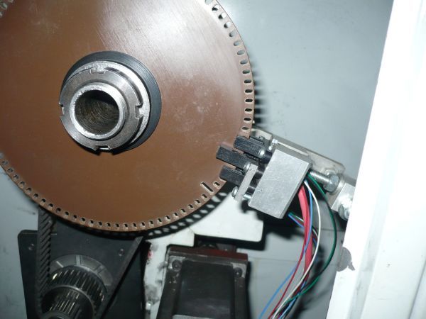
              I'm using 90 on my lathe with a home made encoder disk ade from 3mm or 4mm tufnol sheel.

              90 slots one of which is longer. Three opto switches from RS, one controls leading edge, one controls trailing edge and the larger one is index.


              I have only shown this as it displays the opto mounting better in that using the threaded rod you can position and tune the opto's to suit any position without having to keep altering brackets etc, handy when experimenting, although mine has been like this for 5 years now.

              Edited By David Clark 1 on 08/03/2012 09:37:52

              #86783
              David Littlewood
              Participant
                @davidlittlewood51847

                And before you shoot him, ask him to stop the blasted adverts appearing all over the right side of (some but not others) threads!

                David

                #86792
                russell
                Participant
                  @russell

                  i've just (about) finished a speed display on my mill. I used a reflective style photo-interrupter
                  (ex some unknown piece of equipment). As a reflective device. I simply printed out a disk of 60
                  black-and-white segments, glued it to the top of the spindle pulley, and mounted the interrupter
                  over it.

                  This feeds a $20 digital frequency meter. 100 rpm = 6000 pulses per 60 seconds = 100 Hz on
                  the display.

                  (plan A was to produce a large disk with 60 holes overhanging the pulley, using a slot-type
                  interrupter. This way i dont have a sharp disk spinning around)

                  It works, but the display is a little unstable. I think i still need to adjust the position of the sensor.

                  -russ


                  Edited By russell on 08/03/2012 01:52:10

                  #86797
                  David Clark 13
                  Participant
                    @davidclark13

                    Hi David Littlewood

                    If you see adverts over the text, report the posting, any one on that page and we will sort it out.

                    regards David

                    #86812
                    DerryUK
                    Participant
                      @derryuk

                      I like your disc John S. Can I ask how you made your slots?

                      By extending one slot and using several sensors you have a neat way of syncing your A and Z outputs. What's the max speed you run your disc at and any issues with the sensors rubbing on the disc?

                      Interesting what John H said about being able to change the encoder scaling in LinuxCNC (EMC2), it just so happens that the supplier I had been considering offers a 200PPR at the cheaper price so I think I’ll give one of those a go.

                      Thank you all for your input.

                      Derry.

                      #86843
                      John Stevenson 1
                      Participant
                        @johnstevenson1

                        Derry,

                        Slots were cut on a CNC router with a 2.5mm cutter, max speed can go up to 3,000 but usually runs 2,000 to 2,500. No problem with rubbing as there is about 3/4 of a mill space at either side of the disc.

                        RS part # 455-0919 for the index opto and 455-0868 for the two main opto's.

                        Forgot to add in the earlier post that using 90 slots with leading and trailing edge gives a quadrature encoder count of 360 per rev.

                        John S.

                        #90591
                        Paul Lousick
                        Participant
                          @paullousick59116

                          Have a look athis site.

                          They sell a tachometer suitable for a mill or lathe.

                          You can buy it complete or build your own.

                          Paul J

                          #90592
                          Paul Lousick
                          Participant
                            @paullousick59116

                            Sorry, forgot to add the address

                            Have a look athis site.

                            They sell a tachometer suitable for a mill or lathe.

                            You can buy it complete or build your own.

                            www.machtach.com

                            Paul J

                            #90596
                            Joseph Ramon
                            Participant
                              @josephramon28170

                              Cheap sensors for opto-encoders in old computer mice.

                              Joey

                            Viewing 13 posts - 1 through 13 (of 13 total)
                            • Please log in to reply to this topic. Registering is free and easy using the links on the menu at the top of this page.

                            Advert

                            Latest Replies

                            Home Forums Workshop Techniques Topics

                            Viewing 25 topics - 1 through 25 (of 25 total)
                            Viewing 25 topics - 1 through 25 (of 25 total)

                            View full reply list.

                            Advert

                            Newsletter Sign-up