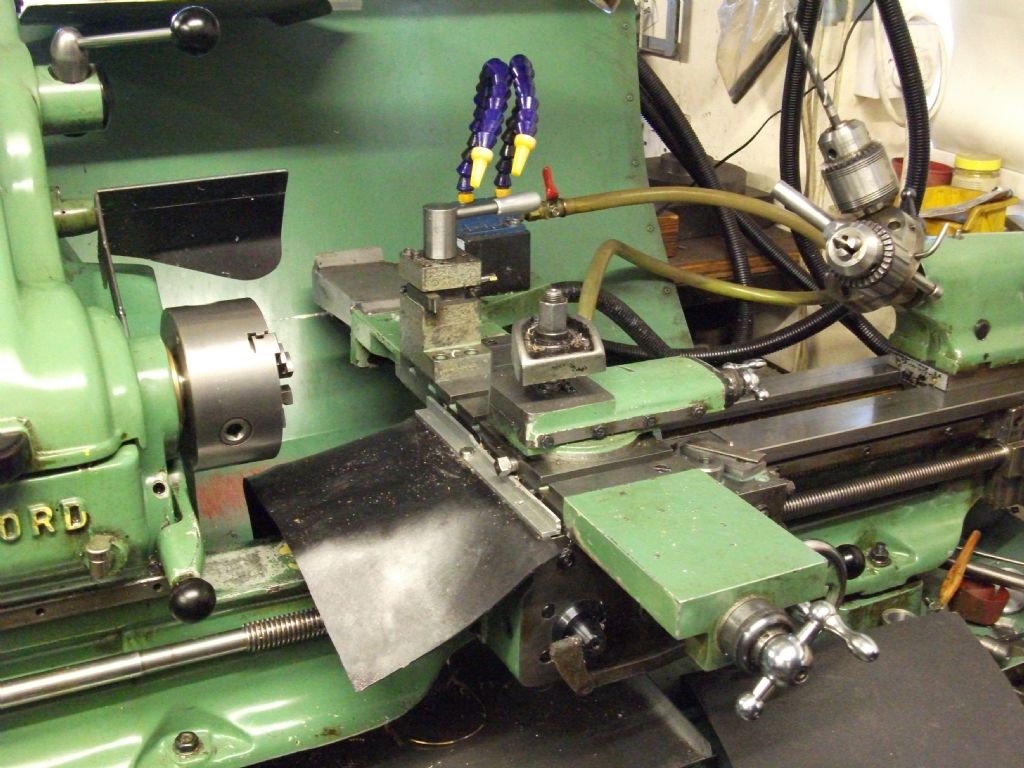
Myford S7 with stepper on cross-slide

Advert

Myford S7 with stepper on cross-slide

Viewing 25 posts - 1 through 25 (of 39 total)
  • Author
    Posts
  • #623035
    Matt Harrington
    Participant
      @mattharrington87221

      Having delved into ELS and been happy with the functionality, I'm now left with wanting more!!

      Has anyone fitted a stepper to the rear of an S7 cross slide? I'm interested to see how neat I can make it. I would also like to add an engage/disengage mechanism for the stepper (although the new ELS system can be set to switch off the stepper motor)

      Any thoughts most welcome.

      Matt

      Advert
      #15402
      Matt Harrington
      Participant
        @mattharrington87221
        #623042
        John P
        Participant
          @johnp77052

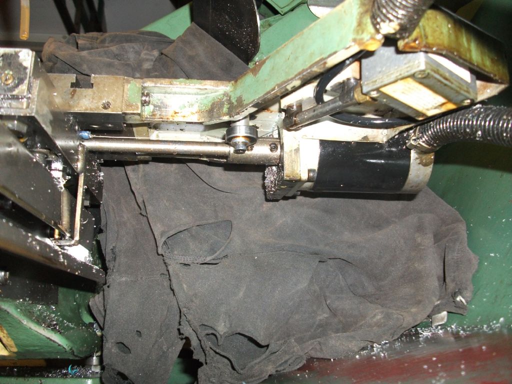
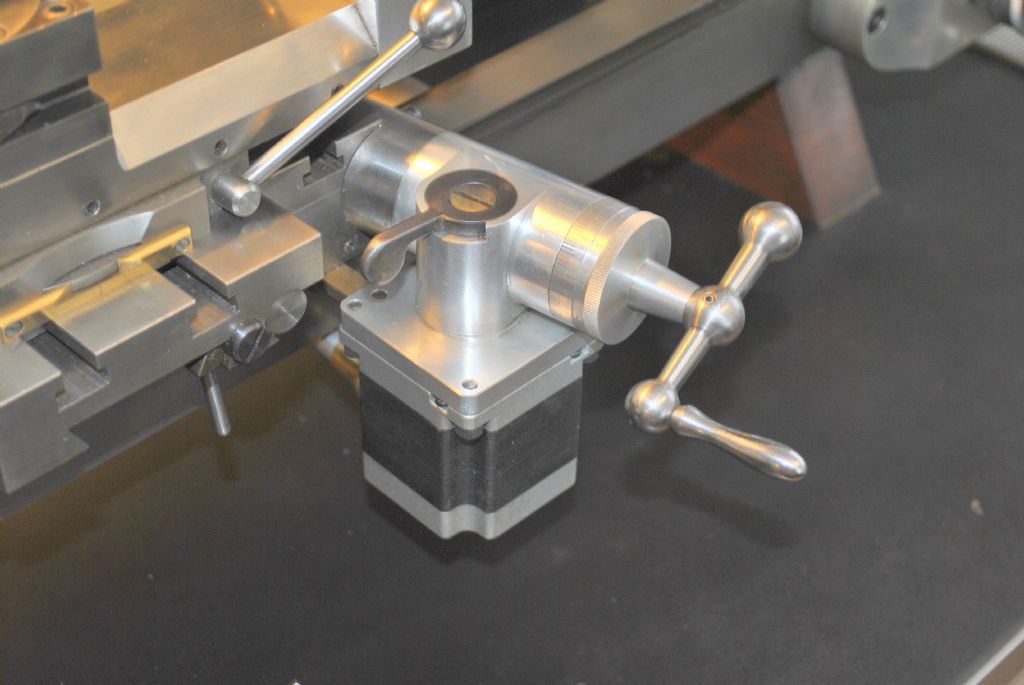
          I converted my Myford about 17 years ago the stepper motor is
          mounted on the rear bracket at the back of the crosslide.I made a complete
          new leadscrew and anti backlash nut and new front bracket to keep
          the slide clear of swarf, the motor is joined to the leadscrew with a solid coupling.

          Johnmyford cnc.jpg

          #623043
          John Haine
          Participant
            @johnhaine32865

            Matt, you are teetering on the brink of a slippery slope!

            I think (can't quite recall as it's years since mine was removed) the problem is that the standard screw doesn't reach the back of the slide casting so would need an extension which is a bit fiddly. Easier to drive from the front end.

            If you were replacing the screw with something longer you might fit a ball screw to get rid of most of the backlash as well as being easier to drive. A non-PXF S7 can only accomodate (I think) an 8mm ballscrew, mainly because of the diameter of the nut which won't fit the "tunnel". Those are available but expensive compared to larger sizes like 12 or 16mm, and need a bearing at the back as well. This is the approach taken by cncyourmyford.

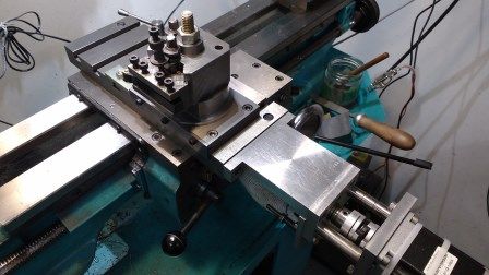
            I use a 12mm screw but in a PXF machine which has a much larger tunnel, and I have the nut "turned round" so the parallel section that normally locates in a bored hole projects out. I drive it direct from a NEMA stepper with an Oldham coupling.

            toolpost2.jpg

            As you see I've fabricated a new bracket.

            Once you have a stepper on the cross slide you'll need to be careful not to slide down the full CNC rabbit hole, though I can tell you that it's very nice once you're in!

            #623120
            Matt Harrington
            Participant
              @mattharrington87221

              Thanks for the photos.

              John P, I notice you still have a handwheel on the cross slide – is it OK to use when the motor power is off? I still like the idea for a manual operation for very quick jobs. Yours looks a neat solution.

              John H, Ha! I've been down quite a few slippery slopes with CNC. I have been considering 12mm ball screws as I have a spare cross slide to play with. I still fancy the idea of the stepper at the back of the cross slide for those manual jobs.

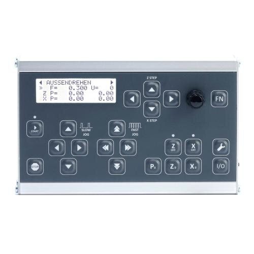
              I have on order a Rocketronics ELS System on order and this will retrofit my exsiting ELS – just on the z axis initially whilst I look at options for the cross slide.

              Matt

              #623146
              Ronald Morrison
              Participant
                @ronaldmorrison29248

                If a stepper motor has power applied it acts as a brake. With power disconnected is turns freely but…it then acts as a generator so it can backfeed any electronics attached to it. Turn it slowly and there is no problem, spin it fast and it can provide too much voltage for the electronics and burn them out.

                #623166
                duncan webster 1
                Participant
                  @duncanwebster1
                  Posted by Ronald Morrison on 30/11/2022 11:39:58:

                  If a stepper motor has power applied it acts as a brake. With power disconnected is turns freely but…it then acts as a generator so it can backfeed any electronics attached to it. Turn it slowly and there is no problem, spin it fast and it can provide too much voltage for the electronics and burn them out.

                  I turn mine quite quickly, never had a problem

                  #623178
                  John P
                  Participant
                    @johnp77052

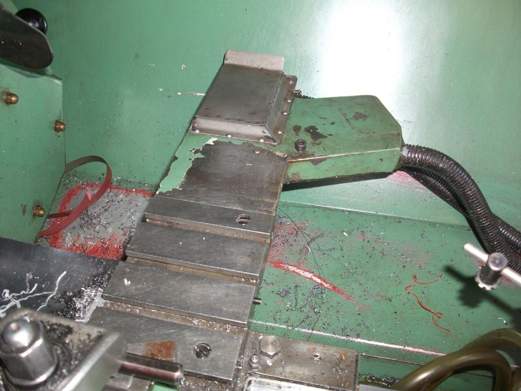
                    Here are some better photo's ,the rear bracket is just fixed with 2 screws ,originally
                    it was just the location for the BW electronics wire DRO ,when i converted to the
                    cnc setup i had to alter the bracket to this "Y" shape to be able to fit
                    the stepper motor and and also the encoder .Fitting at the back of the machine
                    allows the cabling to be out of the way and you don't have the motor hanging out
                    half way across the workshop.
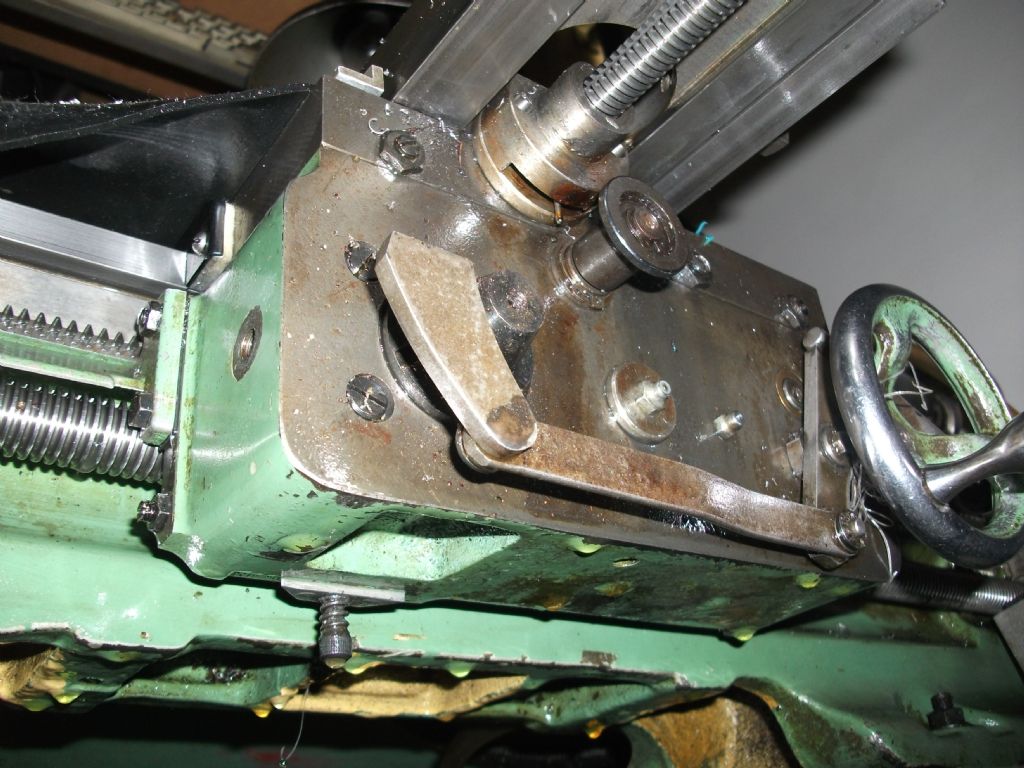
                    I made a new leadscrew to fit the existing nut and it has a top hat oilfilled nylon
                    nut piggy backed on the original nut ,the small peg hanging down in the photo 3
                    allows the second nut to rotate to adjust the backlash ,the retaining housing uses the
                    existing screw fixings and clamps up the second nut to retain it .You can see
                    here in photo 4 the plain part of the new leadscrew and the solid coupling.
                    It is not really necessary to use a ball screw if you are intending to keep the machine
                    as part manual use it would be better off to retain the existing setup ,its 17 years
                    since i changed this screw there is very little wear present ,in any case it is only £7
                    of material and few hours work to make a new one .
                    I have 7 machines that have been made or converted to cnc none of them
                    have ballscrews all except 2 are part manual use ,they all use the same cnc
                    system "Compucut" an old system now but still very reliable, on the Myford
                    i unplug the crosslide axis when it is used manually and use the Compucut
                    system to drive the leadscrew for power feed.

                    John

                    myford cnc2.jpg

                    myford cnc3.jpg

                    myford cnc4.jpg

                    #623183
                    Matt Harrington
                    Participant
                      @mattharrington87221

                      Thanks John, that gives me a clearer picture. The Rocketronics system has a button to power off an individual axis. I shall see how that works when fitted. I'll probably stick with the standard screw for the moment but ball screw maybe a future upgrade.

                      Matt

                      #623185
                      Matt Harrington
                      Participant
                        @mattharrington87221

                        Any thoughts on the power required for the cross-slide stepper – not much I suspect?

                        Matt

                        #623262
                        John P
                        Participant
                          @johnp77052

                          Hi Matt,

                          If you decide to modify your machine in this way and have a rear
                          mounting bracket there is one other thing that you may need to do.
                          The rear shear oil nipple is located in position 13 in the handbook
                          will be difficult to access with a rear bracket in place.
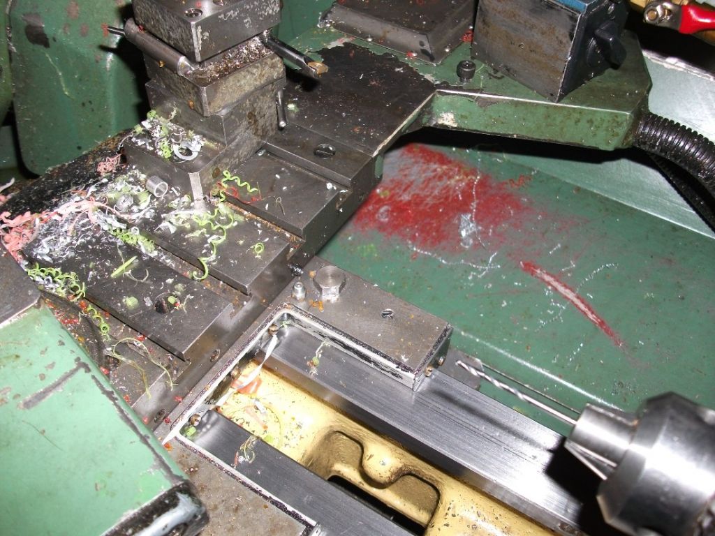
                          I modified mine and re-positioned close to the locking bolt as in the photo ,it just needs some
                          careful drilling this needs to be done with the saddle off the machine
                          at the same time i drilled through a small hole from each of the
                          diagonal slots on the lower part of the slide through to the dovetail
                          ways of the crosslide so when the machine is oiled some lube
                          finds it way to the crosslide.

                          As far as i can remember the crosslide stepper motor came from
                          RS was 23 size @ 1.2Nm and on a unipolar system it has always
                          had enough power ,Myfords can be a problem with cnc it is very
                          easy to dig in and stop the spindle , mine only has a 1/2 Hp motor
                          the real problem is the belt drive will probably slip first unless
                          you have it really tight.
                          I have the same on a larger Warco gear head lathe it only has a single
                          stack 34 size motor even with the 1.5 Hp motor it still has enough
                          power to overcome the spindle.

                          John
                          Workshop17.jpg

                          #623264
                          John Haine
                          Participant
                            @johnhaine32865
                            Posted by Matt Harrington on 30/11/2022 17:11:07:

                            Any thoughts on the power required for the cross-slide stepper – not much I suspect?

                            Matt

                            Mine is driven directly by a NEMA 23 motor probably running at about 1.5 amps 40v. It is a ballscrew so a conventional screw may need more – originally I used an ordinary screw in a bronze nut and had a 2:1 pulley reduction.

                            #623273
                            Mike Poole
                            Participant
                              @mikepoole82104

                              A ball screw will require to be connected to something to restrict free rotation. If a stepper is intended to be always connected then that should be ok but if a manual only handwheel operation is provided then the cutting loads could move the slide.

                              Mike

                              #623280
                              Matt Harrington
                              Participant
                                @mattharrington87221

                                Yes, I agree Mike. Let me experiment first and then I'll see which direction I go in.

                                John, Thanks for that – a starting point for me…..

                                Matt

                                #623282
                                John Haine
                                Participant
                                  @johnhaine32865

                                  Just another data point. As the lathe was switched off I tried leaning on the cross slide, it didn't move. Then as an experiment I loosened one side of the motor coupling and leaned again, and it still didn't move. There isn't a lot of friction in the bearing, it has 2 ball thrust races either side and a needle roller in the bracket, but clearly enough to resist the screw rotating under at least some load.

                                  #623372
                                  Matt Harrington
                                  Participant
                                    @mattharrington87221

                                    I found this article and it looks to be along the right lines for my install – at least for my cross slide. I already have the Z stepper installed as is the encoder.

                                    Myford S7 ELS4 install

                                    Matt

                                    #640219
                                    Matt Harrington
                                    Participant
                                      @mattharrington87221

                                      Well, the warmer weather has allowed me to carry on with the ELS project. One point to note – if you choose the Rocketroincs system the software for the PRO4 version is not the same as the BASIC system. The basic has a facility for threading if you only have the Z axis motorised. (auto pauses for retracting and feed in) The PRO version does not. (although the website at the time claimed the software was identical)!!

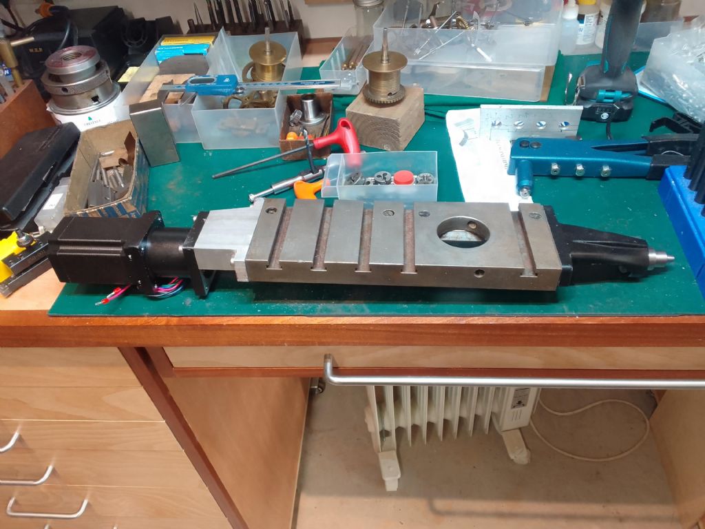
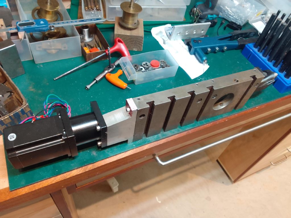
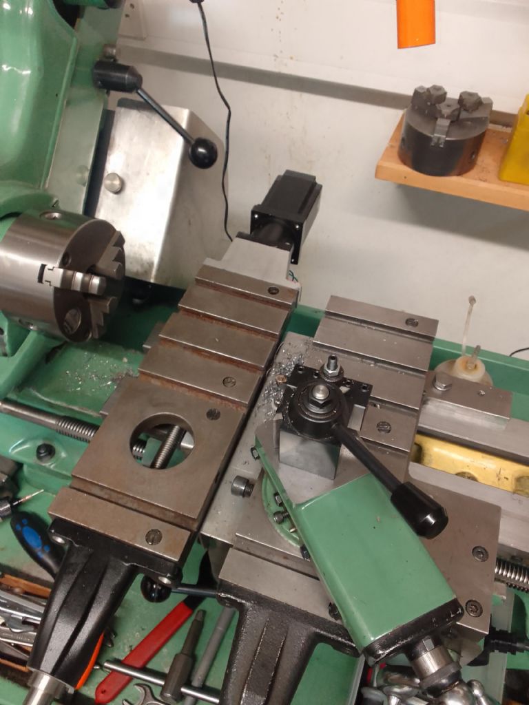
                                      Anyway, on with the update. This photo shows the general layout. (I'm using the standard screw for the moment)

                                      cross - top.jpg

                                      cross - side.jpg

                                      This shot compares the standard cross slide 'v' the modified.

                                      cross - compare with std.jpg

                                      The next shot is the underneath. The bracket needs a little work here. Initially to give a little space for the screw. I will 'hog' out the underneath as well should I need extra travel for the dovetail. (I can't remember ever having to use the cross slide so far forward.

                                      cross - underneath to be cut.jpg

                                      The screw was extended using 10mm rod – this cleared the leadscrew nut. It has been dowelled and will be loctited into place. Whether it needs pinning, we will see later.

                                      I will probably turn the stepper adapter around to reveal the oldham coupling and allow me to easily unclamp when assembling. Still a bit to go but it gives you an idea…..

                                      #640227
                                      Alan Jackson
                                      Participant
                                        @alanjackson47790

                                        You could do it this way and used an eccentric to engage or disengage the stepper motor from the feedscrew. It will also enable about a 10:1 reduction gear ratio. My one is geared down 10:1

                                        Alan

                                        Cross slide stepper drive

                                        #640233
                                        Matt Harrington
                                        Participant
                                          @mattharrington87221

                                          The idea of an eccentric lever is an elegant one. Once my 'proof of concept' is working, I think that setup in place of the coupling would be a decent upgrade.

                                          Matt

                                          #641303
                                          Dell
                                          Participant
                                            @dell

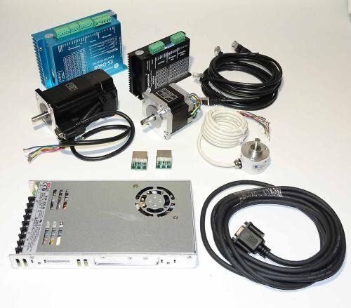
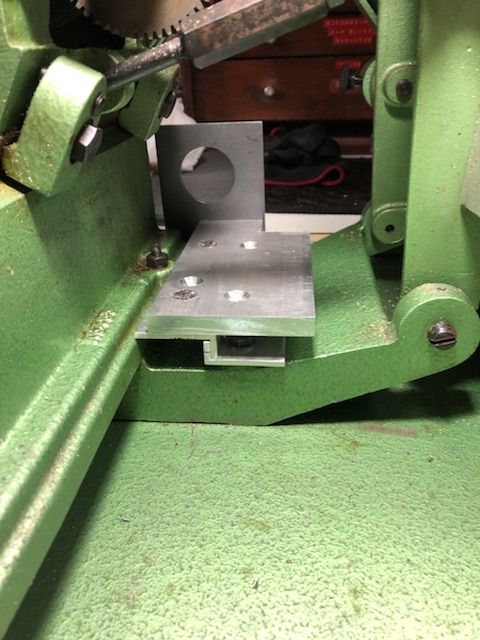
                                            I have been reading this post with interest, due to the problem I have with my hand and getting worse and eyes not as good as they used to be , I have bitten the bullet and ordered the full kit from Rocketronics, I ordered some pulley’s from makers hut and what a load of rubbish they are serves me right for cutting costs so they are going back, I have now ordered some from gear & sprockets, although the kit hasn’t arrived yet ( but cleared customs ) I can’t do to much but I have worked out where to fit the Z stepper and pre made the bracket and yes I did make a mistake and drilled the holes in wrong place but it’s only a mounting plate and the plate is fixed using the 2 bolts that bolt the motor mount so no hole drilling , I am also fairly sure I can mount the encoder where the change wheels were ( fingers crossed) I will start a new post when I get going properly.

                                            Dell

                                            Rocketronics .jpeg

                                            Full kit.jpeg
                                            Mounting for stepper.jpeg

                                            #642579
                                            Matt Harrington
                                            Participant
                                              @mattharrington87221

                                              Dell, I'm sure you can get the encoder to fit within the gear cover on an ML10. I will photo the arrangement for a non gearbox S7 machine and a gearbox one for reference. The encoders have such little resistance to turning that thin bracketry is only required. Matt

                                              #642581
                                              Matt Harrington
                                              Participant
                                                @mattharrington87221

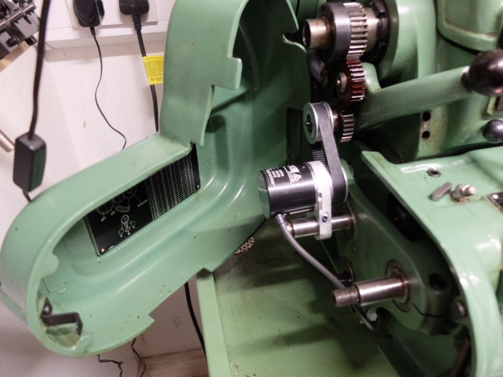
                                                This is the S7 gearbox encoder mount:

                                                dscf9121 (large).jpg

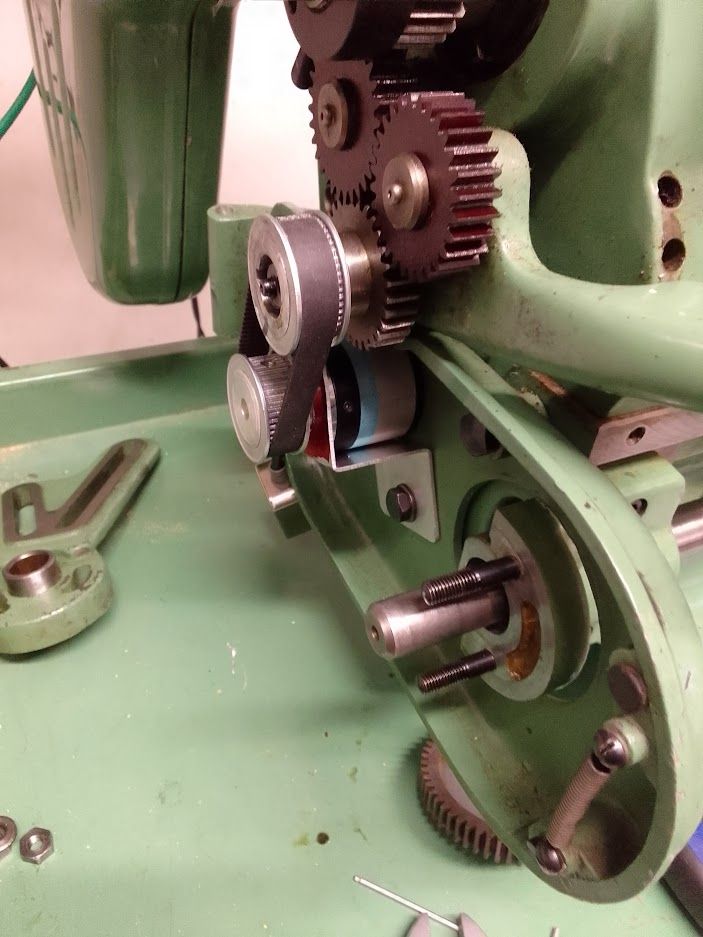
                                                And this is the mount on a non-gearbox S7:

                                                encoder trial on s7 with no gearbox.jpg

                                                I have thinner pulleys to use for the non-gearbox setup but will fit later. The bracket is such that the encoder is flush with the inside of the housing.

                                                Matt

                                                Edited By Matt Harrington on 25/04/2023 18:22:14

                                                #642608
                                                Joseph Noci 1
                                                Participant
                                                  @josephnoci1

                                                  Matt,

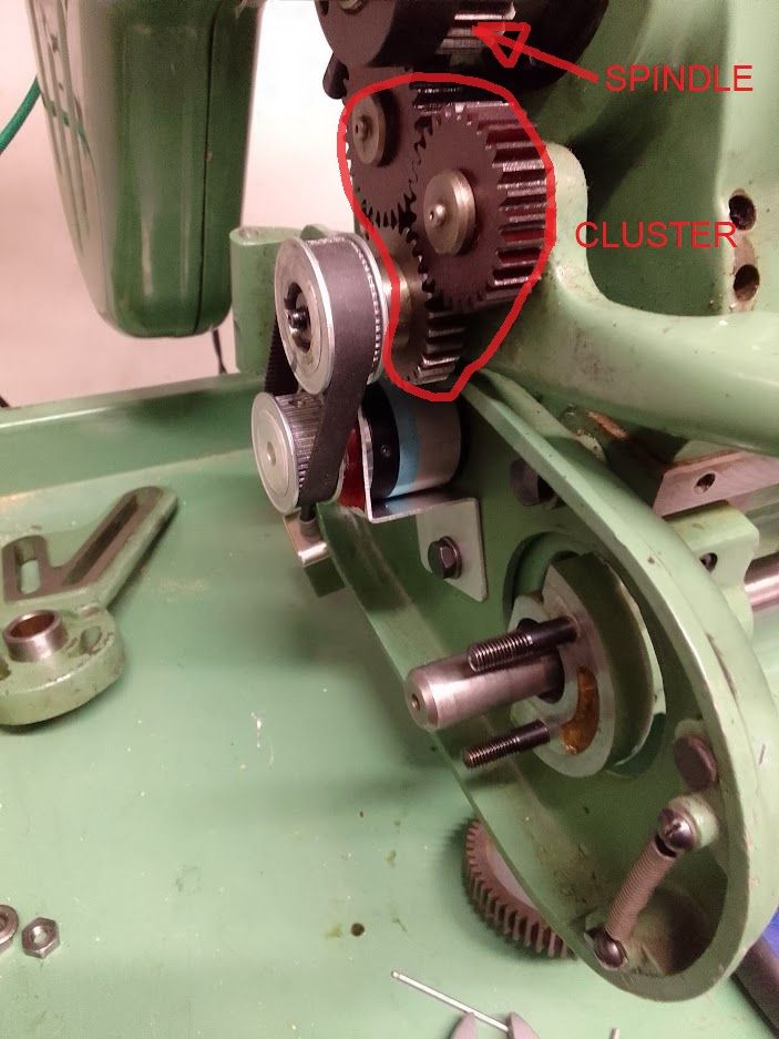
                                                  What is the ratio between the encoder and lathe main spindle? Is it 1:1 ? difficult to see gear sizes, but the spindle gear to feed reversing cluster looks not to be 1:1 ?

                                                  #642613
                                                  Matt Harrington
                                                  Participant
                                                    @mattharrington87221

                                                    Yes, the two pulleys are the same diameter – 1:1

                                                    Matt

                                                    #642620
                                                    Joseph Noci 1
                                                    Participant
                                                      @josephnoci1

                                                      Sorry, I was not clear enough – the GEAR ratios, not the pulleys – as in the edited photo below – what is the spindle to cluster gear ratio?

                                                      ratios.jpg

                                                    Viewing 25 posts - 1 through 25 (of 39 total)
                                                    • Please log in to reply to this topic. Registering is free and easy using the links on the menu at the top of this page.

                                                    Advert

                                                    Latest Replies

                                                    Viewing 25 topics - 1 through 25 (of 25 total)
                                                    Viewing 25 topics - 1 through 25 (of 25 total)

                                                    View full reply list.

                                                    Advert

                                                    Newsletter Sign-up