Sieg / Syil spindle on y axis

Advert

Sieg / Syil spindle on y axis

Viewing 12 posts - 1 through 12 (of 12 total)
  • Author
    Posts
  • #587229
    Matt Harrington
    Participant
      @mattharrington87221

      I was wondering what reason there was as to why both a Sieg KX3 and a Syil X4+ have very similar physical limits on the y axis. the max -y is approx 1" into the table and the max y+ is say 2" beyond the table (nearer to the back of the machine – if any of that makes sense!!)

      This is not normally a problem as a vice sits on the bed but it did get me wondering.

      Anyone managed to increase the limit to the table edge at the front for the y axis?

      Matt

      Advert
      #15383
      Matt Harrington
      Participant
        @mattharrington87221
        #587237
        Clive Foster
        Participant
          @clivefoster55965

          Matt

          Fundamentally the issue is the weight of the head and cantilever stiiffness of the spindle assembly relative to the column dovetails.

          Putting the spindle further away from the column to increase coverage of the table needs a deeper and, obviously heavier, head. The heavier the head is the harder it is to lift it by manual means.

          Being further away from the column the spindle has more leverage relative to the dovetails which reduces stiffness unless the column is correspondingly beefed up.

          The standard sizes and travels seem to provide acceptable price / performance / weight / cost ratios for the person who buys one new. To get more table coverage from that design appears to need a bigger, heftier, more expensive machine. Given the relatively shallow pockets (by machine tool buyer standards) of the target market more sophisticated design and components that could allow greater table coverage are simply unaffordable.

          That said I'd like to try turning the column sideways and mounting the head on a short stiff tube. There are certain strength and stiffness advantages to that layout. Whether such an asymmetric machine would sell is another matter.

          Clive

          #587246
          JasonB
          Moderator
            @jasonb

            It's mostly because as they have the Y axis stepper motor towards the rear of the table under the column rather than hug out the front like most DIY conversions so that limits travel a bit.

            This is why the Y axis movement is less than a similar sized SX3

            Turning the limit switches off gives a little more movement on the KX3 which I have done when machining flywheels.

            Edited By JasonB on 25/02/2022 19:52:14

            #587421
            Matt Harrington
            Participant
              @mattharrington87221

              Jason, The Syil Y Stepper is at the front of the machine and the Sieg, as you say, near the back yet they still have similar travels. As said, I was talking about physical limits rather than those constrained by the limit switches.

              Clive, I'm actually wondering why the table movement is restricted moving towards the column rather than bringing the spindle 'out'.

              The fact that both machines are similar, makes me think they came from a common design.

              Matt

              #587425
              JasonB
              Moderator
                @jasonb

                They came from the Sieg Design

                #587430
                Matt Harrington
                Participant
                  @mattharrington87221

                  Jason, that makes sense as I can see the restrictions of the Y movement on the Sieg and not on the Syil. Hence the Syil is a copy….

                  Matt

                  #587457
                  Clive Foster
                  Participant
                    @clivefoster55965

                    Fundamentally these are manual machines with CNC bolted on afterwards.

                    With the exception of Deckel and Bridgeport style mills it seems to have "always" been normal practice for manual mills to have restricted Y axis travel towards the column so the outer side of the table cannot be covered by the spindle centre line. I've no idea whether there are fundamental engineering reasons. Its just the way things have "always" been done.

                    Similar to the unreachable ends of the table at the left and right ends.

                    I guess it provides safe space for work-holding devices like the common step bolt and strap sets.

                    Whether this was intentional right from the start of vertical mill evolution or whether some mills happened to be made that way and the spare space was found useful so it became the norm I know not.

                    It seems clear that vertical mill design evolved from the simple drill press, which inherently has unreachable table space, rather than the planer which is able to machine over its whole table. Presumably a matter of price / performance ratio back in the early days as a simple "drill press with x-y table" layout would have been less costly to make.

                    Modern full on industrial Vertical Machining Centres are made so the spindle can cover pretty much the whole table. To eyes used to manual vertical mills the tables look very small. Especially in relation to the big box enclosure.

                    Although possibly more objectively accurate, specifying machines by the actual area covered by the spindle rather than by table size would not be a successful sales tactic!

                    Clive

                    #587463
                    JasonB
                    Moderator
                      @jasonb

                      Clive, the KX3 does not share any parts from the X3 or SX3, all totally different castings as they are far more substantial than the similar sizes manual mills to damp down vibration.

                      I'll post a pic of the SX2.7 later and show that the outer edge of the table can easily be reached and more

                      If you were to be able to get the spindle over the ends of the table you would not have much in the way of dovetail engagement!

                      #587478
                      Clive Foster
                      Participant
                        @clivefoster55965

                        Jason

                        Apologies for not keeping up with things. Hadn't realised that the SX2.7 had enough travel to reach the edge of the table. The little Taig CNC on my other bench that I've never got round to using pretty much can too.

                        I appreciate that the castings and other details are modified to be more CNC orientated rather than simply doing a factory version of a DIY bolt on bits conversion to a manual machine but the overall concept is still very similar. Presumably for manufacturing cost / performance / capability ratio reasons. Generally when you look into the "Why did they do it That way when This way is (theoretically at least) so much better?" the answer tends to be "Wanna pay two (or three or X ) times as much!".

                        Industrial, enclosed, CNC VMC machines are generally inverted compared to manual machines with smaller tables running on longer ways so you don't have the limited dovetail engagement at extreme travels issue. Expensive to make but great for rigidity. In exchange you have work-holding issues, if you want to exploit the full machining area there is nowhere for hold-downs to go.

                        Its arguable that a table narrow enough for the spindle to cover the whole Y axis travel is too narrow. A bit of extra width on the outside for hold-downs, clamps, positioning fence for repeat jobs et al is very useful at times. I drive a Bridgeport these days and clamping, work holding et al can be a right pain when the area to be machined approaches the table width.

                        After a bench top mill I thought a 9" x 42" table would be more than enough! Third job said "Nope!". But I'm home shop guy working in 12" to the ft scale, not model maker. My biggest job, so far, was 14 ft long.

                        Clive

                        #587494
                        JasonB
                        Moderator
                          @jasonb

                          It would certainly be nicer to have more Y movement on the CNC for things like flywheels, something like a Haas CM1 compact has 300 x 250 table movement compared to the KX3's approx 300 x 140 but it may take me a while to save up for one.

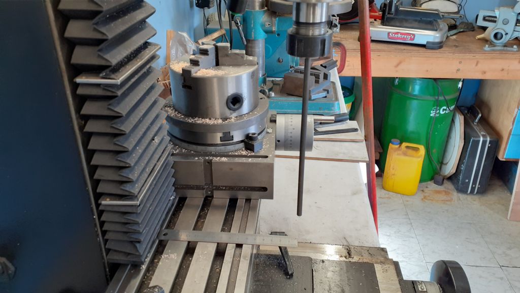
                          This shows the SX2.7 where you can get the spindle 50mm infront of the table and almost to the back

                          20220227_133243.jpg

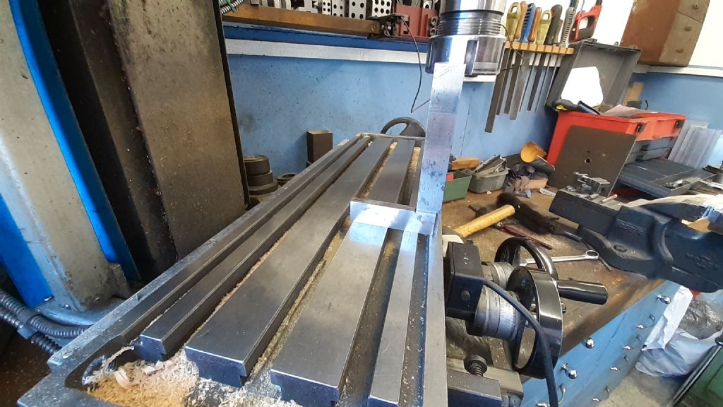
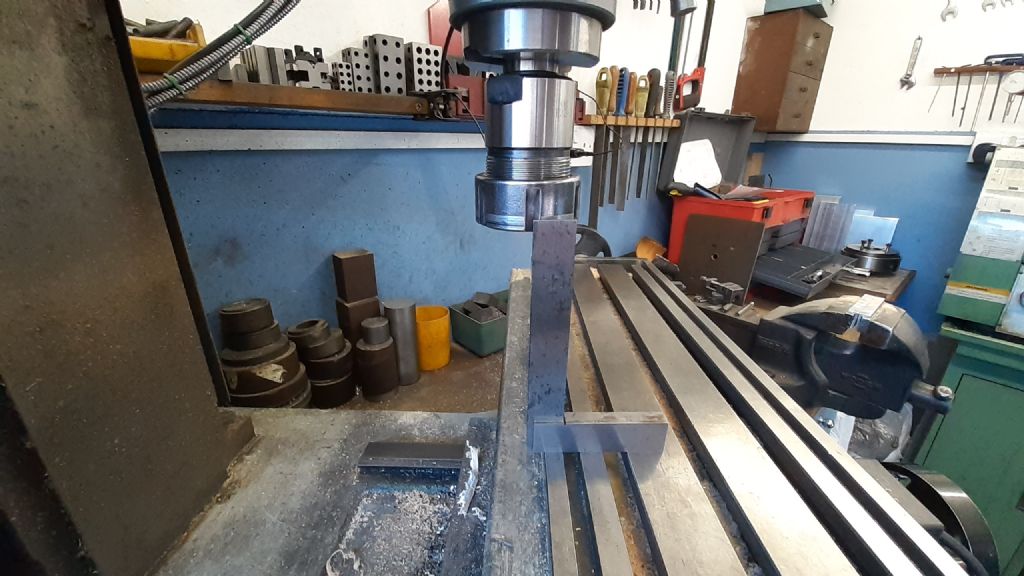
                          And this is the X3 which I lost a little movement on when I fitted the DRO but once you have acutter in there you can more or less cover the table width.

                          20220227_133457.jpg

                          20220227_133535.jpg

                          #587562
                          Matt Harrington
                          Participant
                            @mattharrington87221

                            Jason, Yes, a CM1 would be rather nice in the workshop!! From what I remember, the x and y travel are similar. Still, we can all dream…..

                            Matt

                          Viewing 12 posts - 1 through 12 (of 12 total)
                          • Please log in to reply to this topic. Registering is free and easy using the links on the menu at the top of this page.

                          Advert

                          Latest Replies

                          Viewing 25 topics - 1 through 25 (of 25 total)
                          Viewing 25 topics - 1 through 25 (of 25 total)

                          View full reply list.

                          Advert

                          Newsletter Sign-up