Rocketronics Electronic Lead Screw

Advert

Rocketronics Electronic Lead Screw

Viewing 19 posts - 1 through 19 (of 19 total)
  • Author
    Posts
  • #538096
    ChrisB
    Participant
      @chrisb35596

      Been trying to find a way round the fiddly process of changing gears back and forth for threading and turning for quite a while. I had made up my mind I wanted an ELS for my lathe and Clough42 and his very well explained tutorial on youtube seemed the way to go. I also read through the ELS project thread on the forum which was very helpful.

      Then I came across this german site which have a complete kit for different sized lathes, and after reading through their system's functions it would seem it's one step short of turning your lathe into a CNC.

      Apart from the thread cutting functions, it will do tapers (that is I can do away with the compound and replace with a solid tool post), ball turning, DRO function and more. It is expensive tho at around 1K, but with the tools it replaces would probably break even… There are also less expensive less fancy versions as well. I'm tempted!

      What are your thoughts, anyone came across it before?

      **LINK**

      Advert
      #15344
      ChrisB
      Participant
        @chrisb35596
        #538101
        hubertus fischer
        Participant
          @hubertusfischer33464

          fitted a rocketronics els- to my emco compact 8 and i am very happy with it.

          #538103
          Bazyle
          Participant
            @bazyle

            You haven't said which lathe you have but below £3k adding an extra £1k to your budget will get you into the realms of a very good lathe for amateur use. This device, being specialised electronics will become virtually worthless the moment it is bought, and uness from a major supplier has no garuantee of long term support.
            The link you have given seems to be a £500 CNC type controller.??? I haven't tried translating it.

            #538110
            ChrisB
            Participant
              @chrisb35596

              My lathe is a WM280v. I think the product is aimed at hobby machines which might be bigger or smaller than mine without a gearbox.

              Yes the link is for the controller correct, but they have kits with motors to drive both axes **LINK**

              The website is both in english and german (it's translated by default on my pc tho) and I do believe they have support as I have asked them some questions, particularly if the system is adaptable to an imperial leadscrew lathe, which I'm told it is. He also said currently the system works in metric but they are working to include inches, so I guess it is still in development,

              #538114
              John Haine
              Participant
                @johnhaine32865
                Posted by ChrisB on 05/04/2021 08:01:58:

                ……..

                Then I came across this german site which have a complete kit for different sized lathes, and after reading through their system's functions it would seem it's one step short of turning your lathe into a CNC.

                Apart from the thread cutting functions, it will do tapers (that is I can do away with the compound and replace with a solid tool post), ball turning, DRO function and more. It is expensive tho at around 1K, but with the tools it replaces would probably break even… There are also less expensive less fancy versions as well. I'm tempted!

                What are your thoughts, anyone came across it before?

                **LINK**

                Well to all intents and purposes it is full CNC with a wide range of internal wizards. It isn't clear if you can run g code from external CAD/CAM which would be a serious limitation IMHO given the price. So ~£500 for the control box, then you need motors and drivers and PSU. John Stevenson looked at some of this type of packaged controllers – have a look at this thread – and was very impressed.

                One thing this unit doesn't seem to support is probing to support tool setting which is a serious shortcoming in my view.

                #538118
                John P
                Participant
                  @johnp77052

                  Hi Chris

                  Looked at the linked site seems to be a complete package to do what you wish.
                  I suppose the real problems is fitting it to the Warco WM 280 lathe ,the Emco
                  from the 2nd poster Hubertus Fischer is much the
                  same as a changwheel Myford 7 lathe where direct access to the leadscrew is
                  possible ,with the Warco the leadscrew is connected though the gearbox.
                  I fitted a cnc system to my GH 1000 warco lathe and faced similar problems
                  it was featured as an article in MEW 207 to 212 i got around the leadscrew/gearbox
                  by fitting a removable second leadscrew ,the whole conversion only needed the
                  fitting of about 5 additional screw holes and still retained the full manual machine
                  operation.
                  There was some criticism about the article in this thread

                  https://www.model-engineer.co.uk/forums/postings.asp?th=88623

                  mostly by people who had not bothered to read the article properly ,one even
                  claimed that i had some complicated , " the gears, helical planetary ones" ,
                  of which there were none.

                  It would be worth looking at the mechanical connections needed before
                  committing yourself to proceeding with this type of conversion.

                  John

                  #538121
                  JasonB
                  Moderator
                    @jasonb

                    I would have thought leaving the gearbox in "A" which is a direct 1:1 drive would not be a problem apart from any possible backlash .

                    You do have the added complication of a feed shaft and lead screw so would need to decide if just the leadscrew was going to be used all the time or still have a way to use the feedshaft for manual machining (assume the handwheels can still be used? )

                    Few videos of it in action on their channel

                    #538130
                    Kiwi Bloke
                    Participant
                      @kiwibloke62605

                      Jan Sverre Haugjord puts interesting videos up on the 'Tube. Several are about the ELS. Quite a few on scraping, too.

                      #538155
                      duncan webster 1
                      Participant
                        @duncanwebster1

                        I made a ELS to the design by Joe Noci, I wouldn't be without it now. All up cost probably well under £200, but I didn't keep track

                        #538177
                        ChrisB
                        Participant
                          @chrisb35596

                          Hadn't thought of the gearbox and feed shaft, probably could work if left on the A selector Jason, but not being directly driven backlash would be a problem for threading I think. As for manual control, reading through the manual, it can be manually controlled and the handles should stay.

                          #538184
                          JasonB
                          Moderator
                            @jasonb

                            The other option would be to drive the leadscrew from the tailstock end, should be enough sticking out the end of the bracket to fit an adaptor to. Then you can just use the gearbox to drive the feed shaft and never move the selector to screwcutting position.

                            That will get rid of any backlash in the leadscrew, you just need to sort out the cross slide screw backlash if you want to do say ball cutting as cross slide will need to move in both directions.

                            #538319
                            ChrisB
                            Participant
                              @chrisb35596

                              That would be a good option Jason. That will give me two modes of operation, either in manual control with automatic feed as the lathe came originally, and ELS control via the leadscrew.

                              Reading through the manual, there is an input for "X" and "Z" axes backlash, so the ELS will compensate for this during radius turning.

                              #538850
                              Oily Rag
                              Participant
                                @oilyrag

                                I am considering building a CNC cam grinder. This would involve either a stepper driven leadscrew for positioning the saddle longitudinally along the bedway and a ball screw driven by a stepper for the cross slide. The cam would then be formed by controlling the relative position of the cross slide to the rotation of the headstock spindle (by use of an encoder). The encoder would need absolute positioning capability so would likely have to be something like a 4k 'greyscale' type.

                                My concern is would the reaction time of the cross slide be sufficient to accurately grind the cam form given that the peak acceleration/deceleration rate of a cam can be in the region of 0.006" per degree. The ideal speed of the cam for grinding would be around 300 rpm to allow a small enough grinding wheel (running at close to 4,500 rpm) to fit into the space needed. this gives a time per degree of 0.00055 secs which equates to a cross slide speed of nearly 11" per second or 54.5 ft per minute.Can the control systems, both software and hardware, handle these type of positional reaction speeds?

                                I realise that 'professional' systems are capable of these sort of speeds but are the 'hobby' systems capable likewise? Any comments and suggestions would be most welcome.

                                As an additional note the reason for building the cam grinder is that I have a 'spare' bed and headstock and saddle that can be modified – It's too good to scrap and it seems a worthwhile project to make some use of it rather than leave it to 'rust in peace'

                                Martin

                                #538990
                                John P
                                Participant
                                  @johnp77052

                                  Posted by Oily Rag 09/04/2021 14:39:35

                                  I am considering building a CNC cam grinder. This would involve either a stepper driven leadscrew for positioning the saddle longitudinally along the
                                  bedway and a ball screw driven by a stepper for the cross slide. The cam would then be formed by controlling the relative position of the cross slide
                                  to the rotation of the headstock spindle (by use of an encoder). The encoder would need absolute positioning capability so would likely have to be
                                  something like a 4k 'greyscale' type.

                                  My concern is would the reaction time of the cross slide be sufficient to accurately grind the cam form given that the peak acceleration/deceleration
                                  rate of a cam can be in the region of 0.006" per degree. The ideal speed of the cam for grinding would be around 300 rpm to allow a small enough
                                  grinding wheel (running at close to 4,500 rpm) to fit into the space needed. this gives a time per degree of 0.00055 secs which equates to a cross
                                  slide speed of nearly 11" per second or 54.5 ft per minute.Can the control systems, both software and hardware, handle these type of positional
                                  reaction speeds?

                                  I realise that 'professional' systems are capable of these sort of speeds but are the 'hobby' systems capable likewise? Any comments and
                                  suggestions would be most welcome.

                                  As an additional note the reason for building the cam grinder is that I have a 'spare' bed and headstock and saddle that can be modified – It's too
                                  good to scrap and it seems a worthwhile project to make some use of it rather than leave it to 'rust in peace'

                                  Martin

                                  Hi Martin
                                  First of all the speed that you indicated seems a little high,
                                  in this video

                                  the cam is rotating at between 30 to 40 rpm that alone
                                  would solve some of the points that you have raised.

                                  As part of a project that i have still on going i have looked in to
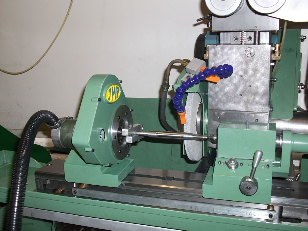
                                  grinding similar forms ,the photo here shows the machine set up here
                                  with the stepper motor drive controlling the rotation of the camshaft axis
                                  ( the shaft fitted here is for something else not a cam)
                                  at 1800 steps per rev, the crosslide moves 0.00005 inch per step.
                                  I wrote a small file to simulate a camshaft but found like you , the
                                  speed as the grinding wheel goes over the peak of the cam the
                                  speed can be too high ,as part of the sequence the rotation speed
                                  of the cam is incrementally reduced and increased as the grinding
                                  wheel rises up and falls over the cam lobe ,i never got to the point
                                  of cutting metal but some of the things that are gained just by these
                                  simulations are of value.

                                  The other thing to think about is at some point during the grinding if you
                                  are using the encoder and crosslide to follow the cam shape
                                  the crosslide will need to move independently to increase the cut depth,
                                  unlike using these systems for threading the grinding is more of a
                                  continuous sequence.

                                  The rocking action of the cam being ground in the video almost
                                  seems like the easiest solution and use the cnc part to make the
                                  master cam.

                                  Johnstepper motor drive.jpg

                                  #539035
                                  Oily Rag
                                  Participant
                                    @oilyrag

                                    John,

                                    Thank you for your valuable comments.

                                    I needed to run the component at around 300rpm to give the correct surface speed for a small(ish) grinding wheel. As shown in the YT videos of the professional cam grinders the wheels tend to be quite large diameter. The 'rocking bed' system was originally pioneered by Brown & Sharpe in their cam grinders but the basis of my machine needed to be based on a fixed bed to utilise the old lathe bed, although admittedly I could build a rocking system to superimpose on the bed itself. The requirement for the master cam and follower (which must mirror the wheel diameter and requires a host of followers to allow for wheel wear) is something I'm trying to avoid. Ideally I therefore want to go from a CAD design straight to the cam form.

                                    I have built one before, about 30 years ago, from a lathe bed and it was very successful in what it did. However it used a hydraulically driven cross slide which was able to achieve very high rates of movement, it did require a separate hydraulic power pack to drive it with 200 bar pressure and used Moog valves to control the motion. We adapted an engine ECU (64 bit) with a dual encoder using hall effect pickups and a 60+1 tooth master spindle trigger wheel and a secondary 29 tooth trigger wheel (to give differentiation) to allow a resolution of 0.06 degree.

                                    I agree with you about the 'nose' speed problem. That can be solved by a programmed variable speed applied to the main spindle, I think!

                                    The infeed would be performed by continual offset steps down to a pre-determined 'stop'. The offset steps only being allowed when motor current indicates the current 'step cut' has diminished to a near 'spark out' level. Or it could attempt to maintain a set motor current level and apply off setting steps accordingly???

                                    Thanks again for your valued contribution.

                                    My apologies to the OP for hi-jacking his thread, I suppose this did deserve a 'New Thread' but sometimes it is easier to jump in when the thread has either got 'tired' or reached a conclusion.

                                    Martin

                                    #539117
                                    John P
                                    Participant
                                      @johnp77052

                                      Hi Martin

                                      Seeing what you have written it would seem that you may be grinding a full size
                                      cam perhaps not for model size engines ,your smallish grinding wheel would be
                                      about my normal size wheel 6 to 7 inch where the difference in size for a cam
                                      blank of about 1/2 inch shows little error from a radius to a straight line.

                                      For the model engine enthusiast these two videos from Sherline may be of
                                      interest. Certainly for me , on seeing these my early attempts i was trying to run
                                      the work perhaps too fast ,the attraction of doing these with cnc is there is little
                                      more to make if you already have a machine as i have.

                                      https://youtu.be/RrpdJHTPXFI
                                      https://youtu.be/PffRGZjagBs

                                      Perhaps you will write again about your cam grinding as it progresses most
                                      probably in its own new thread ,i am sure it will be of great interest.

                                      John

                                      #657629
                                      jaCK Hobson
                                      Participant
                                        @jackhobson50760

                                        I'm currently installing on an old Super 7. It is a cheap way of getting the equivalent of power cross feed and gearbox (gearbox alone now goes for the cost of the complete kit).

                                        I could easily pull it all off if I switched machines.

                                        The challenge with the install is how to physically connect the components : spindle encoder, x and Z motors.

                                        Some observations:

                                        I have the 'hidden under the cross slide' DRO from machine DRO and this would complicate putting the Z motor on the back of the cross slide (where it would probably look nicest. So I'm putting mind on the front, using a bracket bolted to cross slide T-slot.

                                        The toothed belts/wheels for printers (and 3D printers) are cheap and good for light loads. '2GT' 2mm pitch 6mm wide. Lots of options next day delivery on Amazon. Excellent for spindle encoder… but I didn't find them until I had already used 5mm pitch 10mm wide. I will see if it is enough for cross slide…. an 80 tooth wheel replaces the dial gauge while retaining the handle which is really neat. 60 tooth might work and be even neater.

                                        Certainly happy to stick with bigger belts for leadscrew. I put it on the handwheel end.

                                        Document from rocketronics suggests not to gear down steppers too much (steppers lose torque at higher revs so gear down for torque doesn't always help) and stick to whole ratios.

                                        Now I just have to wire it all up…

                                        #657664
                                        John Hinkley
                                        Participant
                                          @johnhinkley26699

                                          ChrisB

                                          i fitted a Clough42 els to my Asian 9×20 lathe. It doesn't have the bells and whistles of the Rocketronics one, but all I wanted was the convenience of button selectable feed rates and inch/metric threading. I had already made a ball turning accessory and later, a taper turning attachment. The installation is briefly described in an album and more extensibly in a YouTube series of videos. I didn't keep track of the total cost either, but I'd be surprised if it came to more than £350. That includes two Texas Instruments Launchpads, 'cos I managed to fry one somehow.

                                          John

                                          Edited By John Hinkley on 23/08/2023 17:34:23

                                        Viewing 19 posts - 1 through 19 (of 19 total)
                                        • Please log in to reply to this topic. Registering is free and easy using the links on the menu at the top of this page.

                                        Advert

                                        Latest Replies

                                        Viewing 25 topics - 1 through 25 (of 25 total)
                                        Viewing 25 topics - 1 through 25 (of 25 total)

                                        View full reply list.

                                        Advert

                                        Newsletter Sign-up