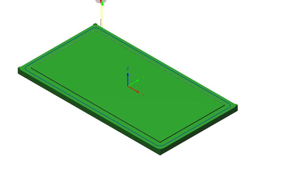
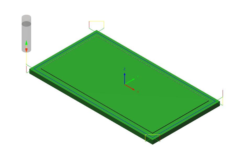
I've got to the stage of attempting a first run with my cnc router. I drew up a 100x50x4mm cuboid in Fusion360, and generated the g-code file attached below. Loading it into Mach4 the preview of the path shows that the tool is going to describe some large arcs at three of the corners – possibly the lines which include I and J codes such as G2 X105 Y51 I101 J51.
Am I right in thinking that this is because I have added or omitted something in one of the F360 dialogs at the manufacture setup stage? Maybe something to do with lead-in and lead-out??
Also, I am confused on setting up the work origin. I have started by homing the spindle and zeroing the X,Y and Z axes, followed by manually jogging the cutter to the corner of the stock. At this point I'm setting G54 in the Mach4 dialog, so the DRO's display the offset (lets say that X Y and Z show 300, 200 and 80 for example). I'm not sure how Fusion360 can use this though – do I have to add a line of g-code along the lines of G54 X300 Y200 Z80? In which case where do I add it? Or does Mach4 use the G54 info I put in to sort out where the cutter actually moves to before it starts running the Fusion360 code?
Sorry for the dumb questions, but it has taken a bit of effort to get this far and I really don't want to destroy the machine before I've done any real work with it! And this first test will be run with the stepper motor couplings disconnected and the cutter removed!!
: (PGM, NAME="1001"
; MACHINE
; VENDOR AUTODESK
; MODEL CNC ROUTER
; DESCRIPTION GENERIC 3-AXIS
; T1 D=8 CR=0 – ZMIN=-4.5 – FLAT END MILL
: G90 G40 G94
G17
G71
; WHEN USING FUSION 360 FOR PERSONAL USE, THE FEEDRATE OF
; RAPID MOVES IS REDUCED TO MATCH THE FEEDRATE OF CUTTING
; MOVES, WHICH CAN INCREASE MACHINING TIME. UNRESTRICTED
; RAPID MOVES ARE AVAILABLE WITH A FUSION 360 SUBSCRIPTION.
M26
; 2D CONTOUR1
:T1 M6
S3500 M3
H0
G0 X101 Y-3
G1 Z20 F175
Z6
Z2
Z-4.5 F1059
X83 F175
Z-3.5
X69
Z-4.5 F1059
X33 F175
Z-3.5
X19
Z-4.5 F1059
X1 F175
G17 G2 X-3 Y1 I1 J1
G1 Y19
Z-3.5
Y33
Z-4.5 F1059
Y51 F175
G2 X1 Y55 I1 J51
G1 X19
Z-3.5
X33
Z-4.5 F1059
X69 F175
Z-3.5
X83
Z-4.5 F1059
X101 F175
G2 X105 Y51 I101 J51
G1 Y33
Z-3.5
Y19
Z-4.5 F1059
Y1 F175
G2 X101 Y-3 I101 J1
G3 X100.2 Y-3.8 I101 J-3.8
G1 Y-4.6
G19 G2 Y-5.4 Z-3.7 J-4.6 K-3.7
G1 Z20
G17
M26
G0 X0 Y0
M30
M2
Steve Pavey.


![20210120_084859[1].jpg 20210120_084859[1].jpg](/wp-content/uploads/sites/4/images/member_albums/44290/886951.jpg)


