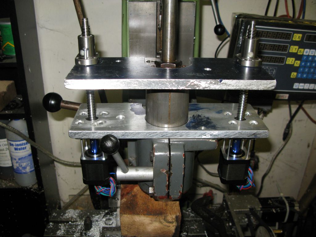
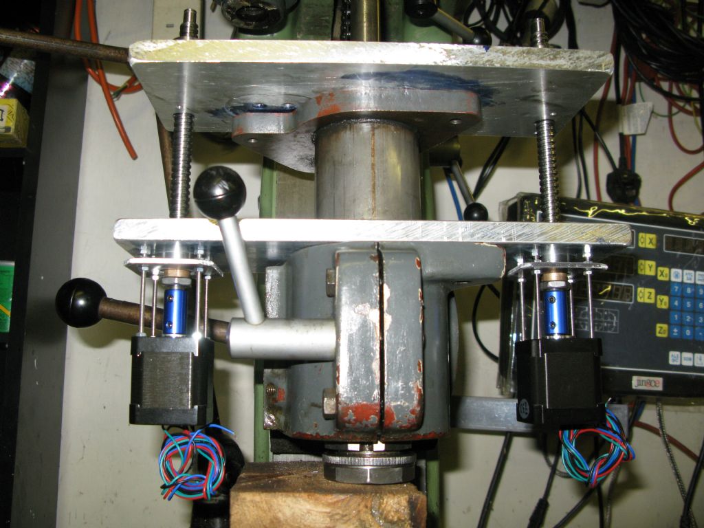
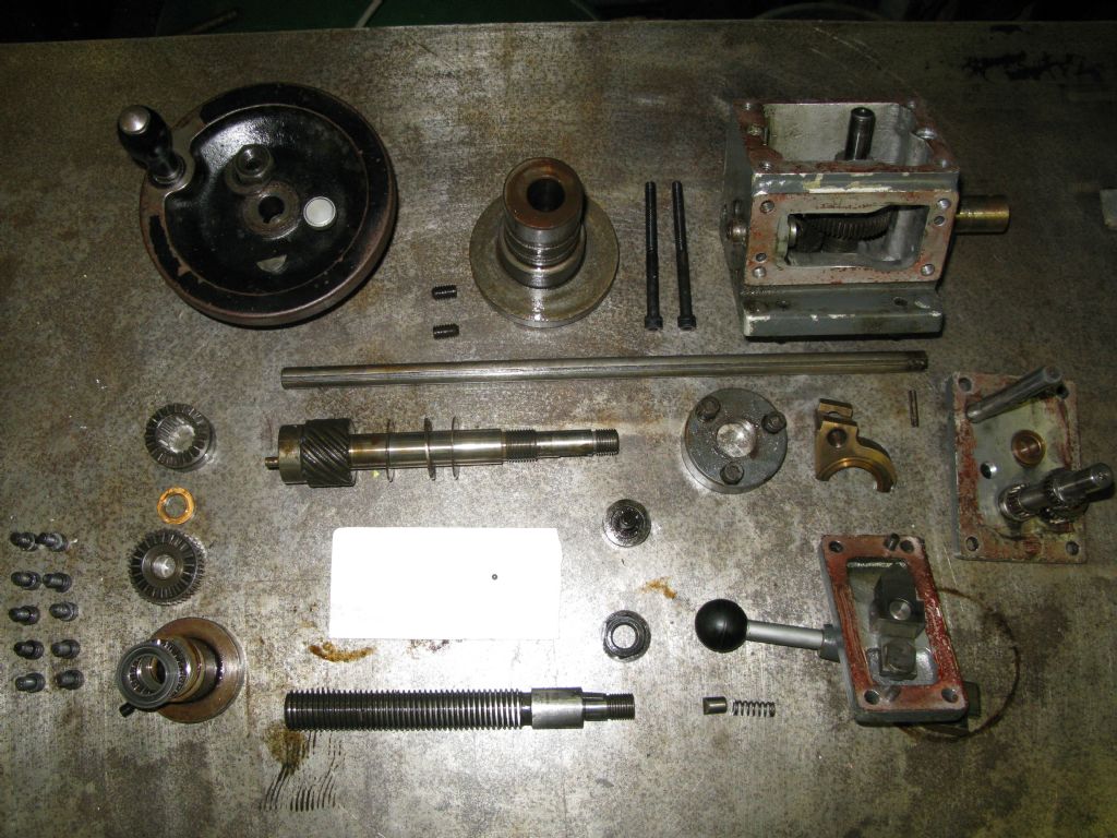
Jig borer CNC conversion
Jig borer CNC conversion
- This topic has 2 replies, 1 voice, and was last updated 24 August 2019 at 22:33 by
Bob McDougall.
Viewing 3 posts - 1 through 3 (of 3 total)
Viewing 3 posts - 1 through 3 (of 3 total)
- Please log in to reply to this topic. Registering is free and easy using the links on the menu at the top of this page.
Latest Replies
Viewing 25 topics - 1 through 25 (of 25 total)
-
- Topic
- Voices
- Last Post
Viewing 25 topics - 1 through 25 (of 25 total)
Latest Issue
Newsletter Sign-up
Latest Replies
- Firth Valve Gear
- Help for DIY lathe build.
- M type top slide conversion??
- Dial test indicator vs Dial indicator
- Request for a Slot to be Milled in a Shaft
- Offen screw type telescopic gauge.
- Bearing boxes for ball race
- Twin Engineering’s heavy mill/drill quill removal
- 2 Machine lights
- IME Watchmakers lathe


