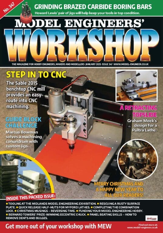
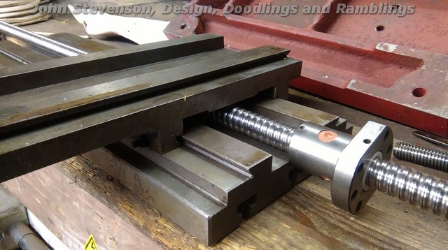
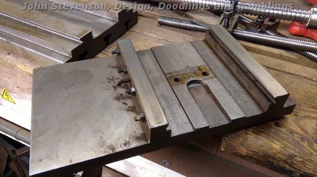
CNC’ing a SX2P mill

Advert

CNC’ing a SX2P mill

Viewing 18 posts - 1 through 18 (of 18 total)
  • Author
    Posts
  • #15116
    John Stevenson 1
    Participant
      @johnstevenson1
      Advert
      #248294
      John Stevenson 1
      Participant
        @johnstevenson1

        Been asked to move the SX2P posts from the Warco WM thread to a new one so that it can be searched easily.

        I will delete these posts from the old thread and replace them with a link to this one.

        Any relevant threads from the Warco post on the SX2P will also be copied over but general replies will be left.

        OK, could be long, go get a coffee.

        First off as mentioned the base on the SX2P is the same as the X1L, sounds funny but the X1L has the longest travels of these small mill and is greater than the original X2 base which is the one fitted to Axminsters offering hence the small table size and bed travels.

        Ballscrews won't fit straight in unless you go down to something like 10mm which as well as not being satisfactory they are very expensive.

        The generic screws made in China at about 3 different factories [ all decent factories BTW ] fall into popular sizes and the 1605's are the most common and hence the cheapest.

        The number is derived from 16mm diameter [ nominal as they are rolled ] and 5mm pitch.

        So the screw for all intents and purposes is 16mm but the body of the ball nut is 28mm and the flange is 35mm but it's possible to cut some of the flange away with no detrimental results, so the secret is getting this 28mm diameter ball nut into spaces it wasn't designed for.

        Now I hope you lot are dually grateful that I've knocked off early, forsaken my pie and a pint just to start a conversion I don't even need.

        First the X axis as it's the first bit to hand.

        There is enough room to get the screw in but not the barrel of the nut. Table is on the bottom and saddle is on the top.

        However if we spin it over it has part of a groove already machined in.

        Now if that groove is opened out all the way thru then the screw can lift up and allow the nut to clear the underside of the bed but still not get inside the saddle.

        So.

        Belt a pocket in with a 30mm inserted cutter to allow the nut to fit. Also mill one of the flats down on the ball nut to the hight of the 28mm part for clearance.

        This gives us this.

        Screw and nut fitted into the space with clearance and needs fastening to the saddle by the two top screws.

        A new housing is needed for the end of the table to carry two angular contact bearings, oldham coupling and stepper mount in a nice block or casting.

        Don't mount the stepper on 4 pillars, it's a machine tool not a bloody clock.

        More to follow in a bit, got to feed the hound.

        #248295
        John Stevenson 1
        Participant
          @johnstevenson1

          OK, Y axis.

          Fast running out of time now so this axis will have to be a mock up.

          On the base of the mill is a standy proud block for the original nut to sit on and this stops anything fitting.

          Block just visible under the circular part of the ball nut. At this point it's a quite thick casting, over 25mm.

          If that block was reduced in thickness by 6mm it would allow a new nut block, bored to 28mm to be fitted. It would mean that both flats on the nut would have to be reduced to the nut diameter and rely on the two side holes for mounting on the nut block.

          Then it just requires the same mounting as the X axis to be fitted to the front of the saddle.

          The Z axis is a whole different ballgame.

          I have seen all types of fittings, none in my book good enough. The side mounted screws cause the head to tilt to one side, same with the rear mounted. The only central mounted screws I have seen rely on a driven nut which makes the whole machine look top heavy and not thought out.

          In the next couple of days I'll post a mock up of the head mounting with ball screw fitted and it looks the bizz.

          Remember he who bodges wins wink

          #248296
          John Stevenson 1
          Participant
            @johnstevenson1
            Michael Gilligan 26/07/2016 22:08:11
            7151 forum posts
            301 photos

            Brilliant demonstration, John star

            … Way above-and-beyond the call of duty.

            MichaelG.

            Message member Message member Ignore member Ignore member Send to friend Send to friend quote Quote quote Report
            Edit posting edit post Delete posting Delete posting Bozo member Make bozo
            Luke Blades 26/07/2016 22:50:54
            11 forum posts

            Cheers John,

            I've been blown away with your support on this one! Great explanation and i'd love to see the finished job.

            I'm now fully confident that this is the way to go. Luckily i've got access to machines at my uni to make the mods.

            Thanks again,

            Luke

            Message member Message member Ignore member Ignore member Send to friend Send to friend quote Quote quote Report
            #248303
            John Stevenson 1
            Participant
              @johnstevenson1

              OK Z axis where all the work is.

              The problem with this machine is lack of space, the motor takes up all the space on top of the head and getting a screw in is not good.


              Head removed from the column and you can see where the rack fits just under the dummy screw.

              Some people have moved the motor forward slightly with different pulleys / belts to allow the screw to be fastened at the rear and use a rotating ball nut which adds to the hight of the machine and looks a bit out of place.

              Some like the kit from CNC Fusion in the States hang the screw off the side.


              Not ideal as it forces the head to bind or tip with unequal forces.


              So looking outside the box the problem is the motor is in the way, so, light bulb come on yet ? ?


              Spin the motor 90 degrees and we have enough room to get the nut where we want it and hold a firms dance.

              Nothing wrong with hanging the motor off the side, the X3 does it and many of these have been CNC'd in the past.


              Two holes have to be re-drilled and tapped in the top and an angle bracket needs fitting to the side to support the rear and cover the exposed belt up. This can also double as a switch box later in the conversion.

              Only thing to take into account is the weight will be more to the left than before, so ,


              So at great personal expense a precision balance plate was machined up from a selected bit of Scrapbinium and the pivot bolt adjusted until the head hung in sideways balance which upon measurement to micron precision it was deemed that the nut needed to be off centre by 15mm.


              So,


              Belt it on the mill and waz a 28mm hole in it and an 18mm hole thru the bottom to allow the screw to poke thru.

              Now if you are not particular you can mount the nut central which will save a bit of work as it breaks into two of the mounting holes and you have to deepen the counterbore and replace two screws with shorter ones.


              Now once cleaned up and few holes drilled and tapped we get this.


              At this point all the heavy work has been done and it's down to making thrust blocks, motor mounts and the rest of the general conversion work but it proves that the SX2P can have large [ and the cheapest model ] ballscrews fitted and still look like a small CNC machine and not a mackle up.


              Edited By John Stevenson on 27/07/2016 21:54:12

              #248304
              Michael Gilligan
              Participant
                @michaelgilligan61133

                NICE ONE

                MichaelG.

                #248306
                Howi
                Participant
                  @howi

                  Now! That IS thinking out of The box.

                  #248311
                  Luke Blades
                  Participant
                    @lukeblades15879

                    Luke: "Hey John can SX2P be converted to CAD?"

                    John: "Yeah, i've got one in the back, gimme a day and i'll do the whole job and document the process"

                    😛

                    Massively grateful for this, if we ever meet, i'll buy you that pie + pint you missed out on for sure!

                    I got a bit lost somewhere in the sarcasm about the positioning of the hole, 15mm off centre. I'ts late and I can't think of why the screw needs to be off centre, forgive me. Is the balance of the head affected drastically by moving the motor round? Couldn't this be solved by counterweights? (Remember i'm a rookie)

                    I was planning to go with the "off the side" z axis ballscrew mounting because that's all i've seen, however this is a very elegant solution. Out of interest how much can the spindle be misaligned by this? The gibs are quite long and I would have thought that they would keep the head vertical with quite a high stiffness. Is this misalignment something you've experienced, read about or predict? It's a nice idea either way (even if only aesthetically) and although i'm fully capable of the mods, that's a lot of crap to haul up to campus! A good excuse to grab a taxi if ever there were one i suppose.

                    Thanks again John, I'll probably be buying the machine sometime this week or next. When i've got it going I shall post some updates and show you how i've gotten on!

                    Best,

                    Luke

                    #248313
                    John Stevenson 1
                    Participant
                      @johnstevenson1

                      Putting the screw 15mm off centre puts the head back into balance.

                      Does it make a difference if it's left central ?

                      TBH I have no idea, probably not but hey it's Wednesday and I'm in full metal jacket anally retentive mode, after Thursday everything normally goes down the crapper. wink

                      #248314
                      Paul Lousick
                      Participant
                        @paullousick59116

                        Thanks John for an excellent post.

                        Regards, Paul.

                        #248326
                        Zebethyal
                        Participant
                          @zebethyal

                          Enjoying the conversion, especially liking the offset motor idea.

                          Biggest downside for some people may be that it requires another milling machine in order to perform the conversion – many of the other conversions, while not necessarily optimal in design are 'bolt-on' with minimal machining.

                          One simple addition that can off-set a side mounted Z axis leadscrew might be to use a gas spring. It could also be used to help the offset motor if doing your Z axis conversion. The spring use also means less work for the Z axis motor. This is a useful and cheap modification even if you don't CNC as it is a vast improvement over the factory spring.

                          Some of these modifications may be more attractive if the various UK suppliers made the castings available as aftersales items like they do in the US.

                          Edited By Zebethyal on 28/07/2016 09:11:25

                          #248327
                          JasonB
                          Moderator
                            @jasonb
                            Posted by Zebethyal on 28/07/2016 09:07:22:

                            Biggest downside for some people may be that it requires another milling machine in order to perform the conversion

                            Assuming a lot of people also have a lathe then it would be quite easy to pop those couple of holes in using the lathe, a simple betweeen ctrs boring bar would get them nicely lined up. And an angle plate would be all that is needed to mount the table to teh cross slide so that too can be machined.

                            90deg rotation of the motor is the simple solution using teh existing parts but there is no reason it could not be rotated just enough to clear the screw and stepper which may be a little more work but would have less effect on balance.


                            Well done John, another tack weld on the bodgers lodge headboardsmiley

                            Edited By JasonB on 28/07/2016 10:01:18

                            #248366
                            John Stevenson 1
                            Participant
                              @johnstevenson1

                              Good heaven’s Jason, don’t even joke about tack welding on the headboard or the Delectable Debs will throw a wobbly.
                              I have to go through a 21 point MOT to even be allowed upstairs.

                              #271625
                              wendy jackson
                              Participant
                                @wendyjackson

                                hi, is there any update on this build. are the motors in, is it complete. would like to know. michael

                                #410171
                                Alexandru Panait
                                Participant
                                  @alexandrupanait

                                  Hi John

                                  I would much appreciate it if you could help me with completing this post

                                  I have an SX2P and I need to convert it to a CNC.

                                  Can you help me please.

                                  Alex

                                  #410238
                                  JasonB
                                  Moderator
                                    @jasonb

                                    The last few issues of Model Engineer have carried a series on doing this conversion.

                                    #411162
                                    malcolm mill
                                    Participant
                                      @malcolmmill78623

                                      can you tell me which issues covered this cnc conversion?

                                      I've looked at the back-issues page but not worked out which copies carry the info

                                      malcolm

                                      #411199
                                      JasonB
                                      Moderator
                                        @jasonb

                                        The series I mentioned started 17th August 2018 Issue 4593 and is currently on part 11 being publishe din alternate issues.

                                        This is not the same conversion as the late JS describes in this thread.

                                      Viewing 18 posts - 1 through 18 (of 18 total)
                                      • Please log in to reply to this topic. Registering is free and easy using the links on the menu at the top of this page.

                                      Advert

                                      Latest Replies

                                      Viewing 25 topics - 1 through 25 (of 25 total)
                                      Viewing 25 topics - 1 through 25 (of 25 total)

                                      View full reply list.

                                      Advert