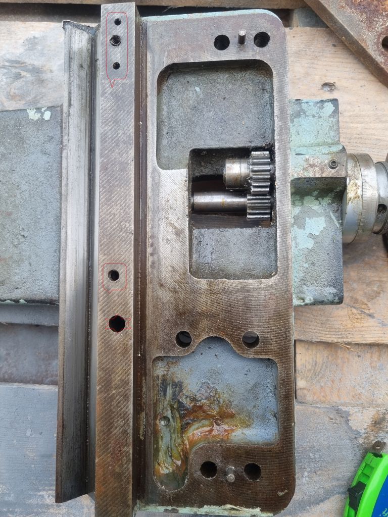
Harrison L5 Carriage lock
Harrison L5 Carriage lock
- This topic has 11 replies, 4 voices, and was last updated 12 November 2023 at 09:25 by
Derek cottiss.
Viewing 12 posts - 1 through 12 (of 12 total)
Viewing 12 posts - 1 through 12 (of 12 total)
- Please log in to reply to this topic. Registering is free and easy using the links on the menu at the top of this page.
Latest Replies
Viewing 25 topics - 1 through 25 (of 25 total)
-
- Topic
- Voices
- Last Post
Viewing 25 topics - 1 through 25 (of 25 total)
Latest Issues
Newsletter Sign-up
Latest Replies
- Westbury Cam Turning Jig
- Measurement history
- Strange drilling situation
- What is (Traditional) Model Engineering?
- FreeCAD version 1.0 released
- Motorcycle General Discussion
- Co-ordinate positioning for circle of holes (not all equally spaced)
- A couple of ‘soon to be available in the UK’ lathes that look interesting
- Lathe vibration in workshop
- Advice on cutting 16mm diameter groove on the lathe


