Still debating whether to try making one , buy a cheap(not so cheap as they used to be) Chinese one or keep searching for a suitable quality used one.
I do however have a rotary table.
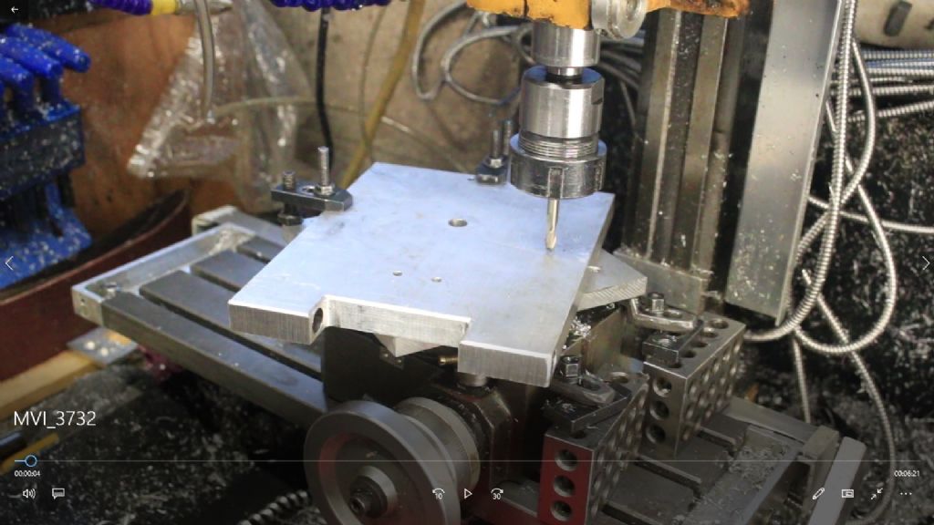
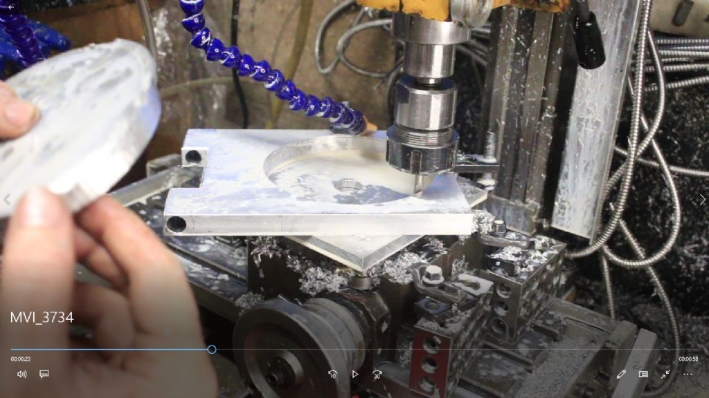
In the absence of a boring head, lets say i have a thinish plate or two that needs a bigger hole in it than can be readily acheived by drilling.
If i center a drilled hole in the plate on the rotary table can i then enlarge the hole to required diameter with an end mill,slowly adjusting in either x or y axis to cut & a lot of cranking of the rotary tables' handle?
For some reason i can't figure out if this works or whether i end up with a correctly sized hole in the wrong place?
I’ve done it with thicker material, Samuel, the way you describe. It worked fine. Just make sure the centre of your hole is directly under the centre of your spindle to start with; a DTI will help achieve this best. If cranking by hand is too tedious you can use a cordless drill to turn the rotary table handwheel.
Personally, I'd centre the rotary table to the spindle, drill a hole through the part, then put a rod the same size as the hole in the chuck, put the rod through the hole and clamp the work down to the rotary table, ensuring that you have a flat sacrificial piece of metal between the work and the table. Hopefully then table, work and spindle are all in alignment. I'd then use an endmill and move the spindle to 1-2 mm from your desired diameter ( taking tool offset into account) then mill in a circle and gradually increase the depth, being very careful when you get close to depth to not let the work break loose, you should be able to make the last cut so that it leaves a tiny web which holds it all together allowing you to prise the middle section out. Then you can move the table again to diameter for your finish cut
In my opinion this works better, I've done it many times before, it reduces waste and saves time rather than milling one gradually increasing circle starting at the centre.
Yes it will work but remember to allow for the diameter of the cutter when moving the table axis to position the work, move 1/2 hole diameter minus 1/2 cutter diameter from the centered under spindle position.
If you have any backlash in the rotary table operating screw take care if climb milling the cutter doesn't grab the work, also lock the axis movements on the mill table before cutting.
I'd make the initial cut a fraction under your final diameter and work down in a series of cuts. Then do the final cuts at full depth so you get a smoother surface. This will also reduce any inaccuracies when using a 4-flute endmill that may deflect outwards and give an oversize hole. 2 or 3 flute would also reduce the tendency to deflect on the initial cuts which will be a slot
If you only have alight mill and a sloppy rotary table then it may be easier to remove the majority of the waste by stitch drilling and then just mill to clean up the edge.
If i center a drilled hole in the plate on the rotary table can i then enlarge the hole to required diameter with an end mill,slowly adjusting in either x or y axis to cut & a lot of cranking of the rotary tables' handle?
….
Thanks.
In effect this is exactly how a cnc machine makes large holes (a/k/a pockets). I used to work at a company making microwave cavity filters, some of which had holes bored to precise diameter and spacing in aluminium blocks. All done on a CNC machining centre, nary a boring head in sight. Material later silver plated.
It works reasonably well, and is quite fast, but don't expect anything like the same level of accuracy or finish as a boring head. And the resulting hole is unlikely to be accurately circular or straight. Whether the hole is acceptable or not depends on what it's for. Not engine cylinders!.
Several sources of error. Emgee mentions backlash and climb milling, and Jason covers a light mill and sloppy rotary table. The state and size of the cutter relative to the hole radius matter too.
In comparison, a Boring head eliminates all these errors, plus the head provides an independent accurate adjustment of the single point cutter that avoids moving the job – always a source of mistakes and error if it can be avoided.
Funny coincedence that this subject should come up at this exact time. I had a job up on the rotary table and after milling out the recesses at 180 degrees from one another, I decided to increase part of the existing bore using a milling cutter and the RT rather than sticking it on the lathe. The increased part was from 1.6" diameter to 1.7" diameter and about 1/2" deep. I used a 12mm endmill and simply took a small cut into the diameter and rotated the work one full turn. This was repeated about 3 times to arrive at the finished size and the finish in aircraft aluminium was excellent. Aircraft aluminium, I hear you say, well it was part of a Wessex gearbox that I was butchering to make part of an oleo leg support. We support oleo legs at the museum rather than relying on the nitrogen pressure used when flying. This dates back to an accident years ago when somebody blew the bottom off a leg and also because any leaks will result in an exibit leaning over. The supports will be hidden under the leg gaiters. The helicopter in question is the Queens Flight Whirlwind at the Helicopter Museum, currently being worked on. The Queen was not allowed to fly in it as it only has one engine, but I believe that both Prince Phillip and Prince Charles both piloted it.
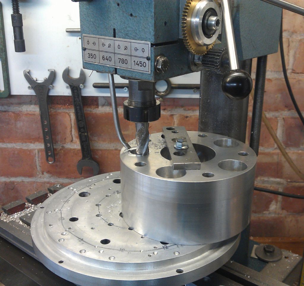
Whilst I do have a boring head, I found counterboring 20 holes much quicker when done on my 'rotating' table.
The holes are 35mm diameter and 40mm deep and the cutter is a 16mm endmill. I put a spigot in the centre of the table to centralise on an already drilled 12mm hole.
The rotary table (a VW front wheel hub with an ali disk from the scrapbox) is manually rotated.
Cutting the counterbores was drama and stress free. With careful adjustment of the cutter feed rate, some jobs can self rotate. The table itself was surfaced by that method with a fly-cutter about 40mm diameter
You can use these kind of "boring head / Fly cutter". I set the cutting diameter by using the drilled hole as reference, backing off the mill the amount requested, loosing the locknut, pushing the bit against the edge of the drilled hole and locking the fly cutter.
The HBM fly cutters look good value for a set of three but the are best used as facing cutters because setting to precise diameter is a very trial and error process.
The advantage of the rotating table is the ability to adjust the diameter of the hole being cut.
When milling the hole, (As Jason says, mill / trepan the hole undersize, and then open up to size by taking a small cut. But be careful not to climb mill. Ensure that the work approaches the teeth of the rotating cutter head on.