WM180 4-jaw

Advert

WM180 4-jaw

Home Forums Manual machine tools WM180 4-jaw

Viewing 14 posts - 1 through 14 (of 14 total)
  • Author
    Posts
  • #634916
    Gareth Jones 11
    Participant
      @garethjones11

      Hi all,

      I've just bought an as-new WM180.

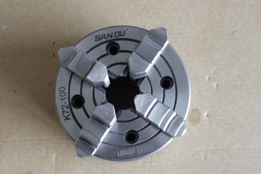
      It came with all the standard bits, including a 100mm 3-jaw and "Sanou" 4-jaw.

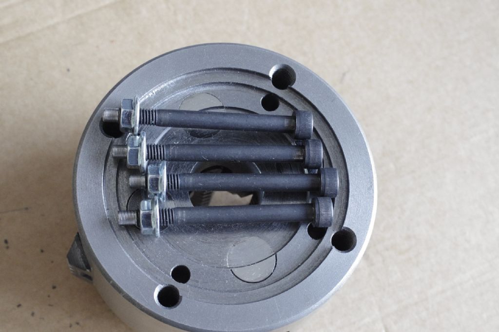
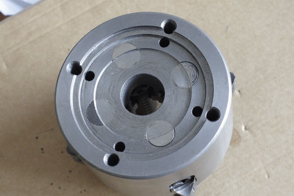
      The 3-jaw bolts directly to the spindle nose but the 4-jaw has a back plate to convert from 4 M8 holes in the rear of the chuck to the standard 3 M8 studs.

      I unbolted the back plate from the 4-jaw and the recess on the rear of the chuck is an exact fit over the register on the nose.

      Assuming I can drill and tap 3 holes in the chuck, is there any reason why I shouldn't eliminate the back plate and bolt the 4-jaw on directly?

      On the rear face of the chuck, the pegs are visible (which retain each jaw screw). I held the chuck in soft-jaws in a vice, gripped a piece of stock in it and heaved the jaws v tight. There was no discernible movement of the pegs. I had worried that, without the backplate, the chuck might try to eject the pegs rearward when tightened hard but seems not.

      Is anyone running such a chuck with no backplate?

      The plate is approx 18mm thick and saving that space on such a short lathe would be great.

      Thanks

      Gareth

      Advert
      #14776
      Gareth Jones 11
      Participant
        @garethjones11
        #634918
        David Ambrose
        Participant
          @davidambrose86182

          On my WM180 the spindle flange is drilled with 6 holes, so it will take my 3 jaw (three holes) and my 4 jaw (four holes) directly, so no backplate is involved. My collet chuck is the same. However, the irregular spacing of the six holes is probably the reason for the vibration at high speeds.

          Edited By David Ambrose on 25/02/2023 14:53:39

          #634920
          Gareth Jones 11
          Participant
            @garethjones11

            Thanks David.

            Does your 4-jaw have the ends of the retaining pegs visible on its rear face?

            Re your vibration – your spindle nose has a 4 hole pattern and a 3 hole pattern (albeit the two patterns share one hole, for a total of six). As both patterns have rotational symmetry, neither should be out of balance.

            #634921
            Gareth Jones 11
            Participant
              @garethjones11

              Excuse the double post – I'm brand new.

              Can I delete it?

              No, but a moderator can!  There's no fee…smiley

              Edited By SillyOldDuffer on 25/02/2023 15:26:49

              #634926
              David Ambrose
              Participant
                @davidambrose86182

                This is my four-jaw:

                3fe5481e-d157-4ba3-97d1-928ba74b8fd2.jpeg

                #634927
                SillyOldDuffer
                Moderator
                  @sillyoldduffer

                  I think the objection is what happens if you make a mess of drilling the holes and/or find in the future that another new chuck has a different bolt spacing. And each hole drilled in the spindle flange reduces it's strength, and messes with the balance slightly.

                  Backplates are less painful to replace than a botched spindle.

                  What's the advantage of doing away with the backplate? The extra 12mm of space is rarely needed in my experience but maybe that's just me.

                  By all means do it if there's a good reason, otherwise seems a risky job for little benefit.

                  Dave

                  #634928
                  David Ambrose
                  Participant
                    @davidambrose86182

                    And although the chucks are symmetric, the holes on the flange are not, so I suspect it would vibrate even without a chuck if I tried it.

                    #634940
                    Howard Lewis
                    Participant
                      @howardlewis46836

                      From the point bof view of concentricity, which is what we want to maximise, it might be better to stick with using a backplate.

                      First job, having fitted it (clean to a clean flange ) would be to face it. That ensures that the chuck seats against a face that is square to the lathe centreline.

                      Then turn trn to OD to tha same size as rhe register in the back of the chuck. (Actually size and size would make it a bit too tight, so maybe 0.0005" to 0.001" undersize would be enough.) Deburr

                      You don't want a loose fit, or the concentricity won't be good. Although with a 4 jaw, you'll be clocking the work and adjusting the jaws to centre the work anyway.

                      Howard

                      #635022
                      Gareth Jones 11
                      Participant
                        @garethjones11

                        Dave – I would never attempt to modify the spindle nose for the reasons you stated. I was only contemplating drilling the chuck body.

                        David – fantastic! Great pic. It looks the same as mine so if you run that mounted direct on the spindle, I can too. Or at least I hope so, because I've just done it – I'm on a nightshift and workload is light fro once, so I had time to set it up on the mill. Clocked the existing 4-hole pattern square and then used DRO's pitch circle function to add a 3-hole pattern. The PCD on the spindle nose is 83.9mm – 84 seems more likely but that's what it measured so that's what I drilled.

                        Another upside is that I've now got a spare backplate, with fixings and register to suit my spindle. Might be useful for oddball one-off fixture plates or whatever.

                        Thanks everyone and especially David for the info I needed to make my first mod' (as attached)

                        Gareth

                        chuck.jpg

                        #635025
                        Nicholas Farr
                        Participant
                          @nicholasfarr14254

                          Hi Gareth, too late now, but I don't know why you drilled three new holes, as you could have used one of the original four holes, and just drilled two new ones, that way the two new holes wouldn't be so close to the other original holes.

                          Regards Nick.

                          #635027
                          Niels Abildgaard
                          Participant
                            @nielsabildgaard33719

                            A lathe made og 180 and 210 parts and a homemade 48mm hole spindle is shown here

                            Chineese upper class

                            and the chuck mounting shown here

                            Front mounting


                            wp_20230226_002[1].jpg


                            Edited By Niels Abildgaard on 26/02/2023 07:19:41

                            Edited By Niels Abildgaard on 26/02/2023 07:32:50

                            #635121
                            Gareth Jones 11
                            Participant
                              @garethjones11

                              That's a mighty spindle on a little lathe. Very impressive. I'd been thinking about front mounting the chucks but I haven't examined them to see if it's possible (pretty sure it is). Might look at a ring/plate to run behind the spindle flange, with the three M8 threaded holes to accept long cap heads from the front of the chuck. That's for another day though as I haven't even run the lathe in anger.

                              Re drilling/tapping 2 extra holes versus 3 – I knew that was an option but the existing 4 holes in the chuck weren't on the exact same PCD as the 3 on the spindle. They were very close (and there's plenty of clearance in the spindle holes). I chose to centre over the register on the rear of the chuck and set the existing 4 holes square to the mill's X and Y. To re-use one of the 4 I'd have had to pick up that hole and a Chinese (or any) threaded hole is not ideal for accurate location. If I was drilling a 4 and 3-hole pattern on the same PCD, together, from scratch, I'd likely use one hole twice and drill 6 in total. There's actually plenty of meat between old and new holes. More than it looks in my pic.

                              Thanks for all replies. The level of response on here is great.

                              Gareth

                              #635153
                              old mart
                              Participant
                                @oldmart

                                _igp2582.jpg_igp2581.jpgI bought a 100mm four jaw independent to fit on my 7 X 12 and modified the body to suit the spindle flange. The original mounts were rear, but there is no reason not to drill the body if necessary for front mounts. The register had to be changed to suit in my case.

                                _igp2580.jpg

                              Viewing 14 posts - 1 through 14 (of 14 total)
                              • Please log in to reply to this topic. Registering is free and easy using the links on the menu at the top of this page.

                              Advert

                              Latest Replies

                              Home Forums Manual machine tools Topics

                              Viewing 25 topics - 1 through 25 (of 25 total)
                              Viewing 25 topics - 1 through 25 (of 25 total)

                              View full reply list.

                              Advert

                              Newsletter Sign-up