Magnetic DRO-S7

Advert

Magnetic DRO-S7

Home Forums Manual machine tools Magnetic DRO-S7

Viewing 22 posts - 1 through 22 (of 22 total)
  • Author
    Posts
  • #595238
    Neil Lickfold
    Participant
      @neillickfold44316

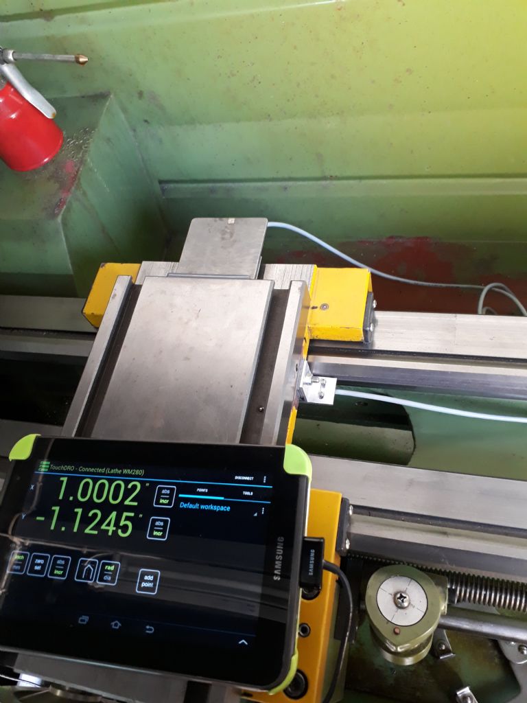
      So the magnetic tape and reader assembly has arrived. I installed the magnetic tape to a piece of Ali extrusion that was double sided taped to the front of the S7 below the carriage, fitting inside the approximate 20mm gap. After getting it all connected and the carrier bracket secured off the thread dial indicator that I don't use, then the disappointment set in. The system I purchased is useless. A steel rule would be actually more accurate. In different places it gives different values. But does repeat very well, within around 0.02mm of the home position. I can wind the carriage along and zero in one direction. Move away and comeback and be within 0.02mm of the zeroed value. but moving say 2 turns and having the table move 6.35mm, the readout can show anywhere from 5.mm to 7mm.

      So now I am looking for a skinny dro system that will fit in the area where I had the magnetic one and write this one off to Don't always trust the reviews provided by the sellers of these things.

      In my Album is the pics of the error in reading at different places on the scale. Here is the installation pics.

      extrusion-installation.jpg

      magnetic-tape-with-protective-cover.jpg

      read-head-mounting.jpg

      clearance.jpg

      carriage-clearance.jpg

      Advert
      #14537
      Neil Lickfold
      Participant
        @neillickfold44316

        Added a magnetic DRO to S7

        #595240
        Michael Gilligan
        Participant
          @michaelgilligan61133

          Sorry to hear your News, Neil

          I am not personally familiar with these magnetic scales, so please take this as ‘academic’

          They are, apparently, quite sensitive to variation in the gap

          Not immediately intuitive, but very nicely explained here: **LINK**

          https://www.touchdro.com/resources/scales/magnetic/overview.html

          I think some experimentation may be in order.

          MichaelG.

          #595261
          Clive Steer
          Participant
            @clivesteer55943

            Thanks Michael for the link to the excellent article about magnetic scales and their sensors which has helped me understand some of the finer points of their operation.

            I only use magnet scales for short distances (<300mm) where the magnetic strip can be well supported and distance between the head and tape accurately maintained. For longer distances I always use glass scales which can tolerate a larger amount of tracking error. However in all cases the read head does have to be very rigidly mounted to ensure there is no flexing due to connection cable tension/movement.

            Newall sell an excellent and compact Magnetic DRO system but they are not cheap.

            CS

            #595262
            Ex contributor
            Participant
              @mgnbuk

              Given that the lightweight section the tape is mounted to is only double-sided tape attached to (presumably) unmachined surfaces, how accurately aligned with the slideway is it ?

              I fitted one of M-DRO's spar mounted magnetic scales to a linisher at work. The spar they supplied is much heavier section than yours appears to be & I spent quite a bit of time aligning it (front & side) with the machine travel to within 0.02 over the full travel – same as I align glass scales. Read head gap was set with a piece of paper IIRC. Readout is accurate & repeatable and has poved far more reliable than the capacitive arrangement it replaced.

              Nigel B.

              #595263
              Neil Lickfold
              Participant
                @neillickfold44316
                Posted by Michael Gilligan on 21/04/2022 00:12:22:

                Sorry to hear your News, Neil

                I am not personally familiar with these magnetic scales, so please take this as ‘academic’

                They are, apparently, quite sensitive to variation in the gap

                Not immediately intuitive, but very nicely explained here: **LINK**

                https://www.touchdro.com/resources/scales/magnetic/overview.html

                I think some experimentation may be in order.

                MichaelG.

                I made a long holder that over lays each extrusion piece. The vertical plane is within 0.03mm the accuracy of the extrusion . The gap is very close, so that may be the source of error. I am not sure. The puzzle is the accurate 9.52 mm pitching in two different regions of the setup. I can modify the holder to increase the gap. But current gap is 0.2mm . I will try the other sensor with a different gap amount and see what the results are.

                 9.52mm-test2.jpg

                As you can see the reading of 9.51mm is quite accurate as the dial is about a 1/2 division short of the full 3 turns of the pitch.

                I found a Newall option that is looking very good, but is beyond my current budget for this project. But it maybe that I just have to dig deep and make it happen.

                Edited By Neil Lickfold on 21/04/2022 09:40:51

                #595266
                bernard towers
                Participant
                  @bernardtowers37738

                  My MDRO kit on my S7 is fitted to the taper turning fixtures on the back of the bed and has not given any cause for concern since it was fitted in May 2017. I also buried the mag tape in the crosslide and buried the reader head in the saddle, a really worthwhile exercise.

                  #595279
                  Neil Lickfold
                  Participant
                    @neillickfold44316

                    That is a kit I had not yet considered was the MDRO S7 kit. I set up the top or Y axis onto the unit, and they measure different values to each other, with neither of them working properly. Even with the added gap, 1mm, it made it no better at all. Obviously there is magnetic setups and Magnetic setups. I am inclined to think the error is in the tape itself. The only thing that really does repeat is the initial zero set for both scales. Neither did exactly 9.52mm for 3 complete turns, being more than .4mm over or under.

                    Thanks for the encouraging responses. I do use the taper turning attachment occasionally, so it is why I want the front DRO. The cross slide is less of an issue for me, but I need a setup that does not effect the attachment being connected.

                    It seems the buried system might be the way to go for the cross slide for sure.

                    Thanks again.

                    #595295
                    Gary Clarke 4
                    Participant
                      @garyclarke4

                      I have one of these kits lying around waiting to be installed. I have seen the buried tape in the crosslide before but have not seen the buried head in the saddle before.. is there a video or pictures or guide for doing that? Neil, if you could document your installation, that may be helpful for others like me!

                      thanks!

                      #595309
                      bernard towers
                      Participant
                        @bernardtowers37738

                        f3a8d9de-353f-403e-acc1-b664c4d79dde.jpegThis is tape and reader head fitment on my lathe26e6ac75-22dc-4467-a6a9-6d5c2a062fa4.jpeg

                        #595314
                        JasonB
                        Moderator
                          @jasonb

                          I would not have thought the handwheel the ideal way to judge the accuracy of movement. Do you have a plunger type dial indicator you can put against the carriage to eliminate any wear and play in the handwheel, leadscrew etc.

                          #595319
                          Neil Lickfold
                          Participant
                            @neillickfold44316

                            Hi Jason, I have used the plunger clock against the carriage as well, and the hand wheel is within 0.02mm every time. So 2 turns is anywhere from 6.35 plus or minus 0.01mm down the length of the bed. I was expecting it to be more error near the chuck, but that is not what I saw. I have been using a 0-50 indicator for the lengths up till now and was hoping this magnetic thing would mean I don't need to set up the semi cumbersome indicator. The errors I am seeing is a long way off. The two read heads on the one tape but at 160mm apart or so, give totally different readings as the carriage is moved along. But when returned to zero, they both read within 0.02mm of each other the correct original place on the tape. So even moving along 1mm they have a large error compared to each other and what it should be.

                            #595323
                            Neil Lickfold
                            Participant
                              @neillickfold44316
                              Posted by Gary Clarke 4 on 21/04/2022 15:35:26:

                              I have one of these kits lying around waiting to be installed. I have seen the buried tape in the crosslide before but have not seen the buried head in the saddle before.. is there a video or pictures or guide for doing that? Neil, if you could document your installation, that may be helpful for others like me!

                              thanks!

                              I just took some pics sort of as I went along. I placed the tape into a piece of 22 wide x 20 high on 2 sides x1.5mm wall section, extrusion cut the near full length of the S7 bed. The tape is cut about 50mm longer than needed so the reader head was always well inside the tape length. The extrusion is held in place by the 3m 19mm wide high strength double sided tape, placed at each end of the extrusion for 100mm long. The lower bed section is cleaned with brake cleaner degreaser. The end hand wheel is removed to allow easy access to slide the extrusion with the tape on down the bed to the very end. The end of the extrusion sit hard against the gearbox. Lightly place the extrusion guessing level. Using a low pressure indicator, travel the length of the bed aligning the extrusion to being parallel . The best i could achieve was 0.03mm as the extrusion is seldom even that straight over its length. Press the extrusion more firmly to the bed checking each time and correcting as needed. Over time the tape adhesion will increase. I used another extrusion siting back over the initial extrusion to act as a cover and guide for the reader head. Before starting, made sure that there was enough room for the tape, protective cover plus the reader head with a gap all fits. Mine was the slimline series reader head. All assembled the reader head has from 0.2mm to 0.3mm of clearance to the tape. The cover piece that holds the read head is mounted into the end piece cut from the length and is about the length of the leadscrew cover to the other side of the carriage long. I removed the thread dial indicator as I have rarely ever used it. The 2 M3 screws that secure the readhead to the cover plate, also holds the adaptor spacer to cover. The adaptor space was just 2 pieces of another extrusion put together. To enable the assembly of that bracket, I used M4 nuts super glued to the inner surface so the screws could be easily assembled. The main holder piece is a but of 3mm section ali extrusion 20x20x3 that I had. When assembled the guide just rests against the main tape holder both front and back. In my case the alignment for a and aft was better than 0.06mm which was totally un planed and was an afterthought and oversight. Only with issues did I check that alignment value.

                              There are more pictures in my album of the details of the read errors and the bits and assembly. The double sided tape is really strong and the most movement pulling back on the extrusion is only 0.02mm and that is a lot more force than the extrusion will ever experience.

                              Now it will be removed before the tape becomes almost impossible to remove and I move on and look at getting something else. I will price the availability of the Newall scale today and go from there. I do like the new Sino LCD DRO though and see if it's compatible with the Newall scales.

                              I may have just a bad set box, and bad magnetic tape too. I am no longer looking at fixing this solution, but going to something more industrial and robust that will still front mount and I will make another sliding cover for the newer setup.

                              Neil

                              #595349
                              ChrisB
                              Participant
                                @chrisb35596

                                Is there a way you can calibrate the reader? I built my own magnetic dro read heads from scratch using components from RLS and an interface from Yury. The interface lets you calibrate the reading against a known dimension such as a 123 block or gauge blocks. Is there any such function in yours?

                                #595368
                                Neil Lickfold
                                Participant
                                  @neillickfold44316
                                  Posted by ChrisB on 22/04/2022 06:58:23:

                                  Is there a way you can calibrate the reader? I built my own magnetic dro read heads from scratch using components from RLS and an interface from Yury. The interface lets you calibrate the reading against a known dimension such as a 123 block or gauge blocks. Is there any such function in yours?

                                  No not that I could see at all. Basically it was junk. Both heads even if reading wrong should have both been at least reading the same numbers or very close to the same. But not even close. What confuses me, it that the return to zero was always correct, no matter what direction it was going.

                                  #595381
                                  Mark Rand
                                  Participant
                                    @markrand96270

                                    Something is very wrong here.

                                    I would say right off the bat, that the outrigger support cantilevered from the thread dial indicator stud is so flimsy that you cannot hope to get meaningful readings. It's susceptible to drag from the cable and friction from the shield all amplified by the twisting of the long cantilevered anluminium angle with a single point of location at the top.

                                    Try remounting the head directly to the apron casting. Also, Get some of M-DRO's aluminium sopport extrusion and screw it to the bed at 150mm/6" intervals, like it's designed to be. When doing that, use shims, to ensute that the clearance is constant.

                                    You don't say who supplied the head and the tape, but I've found the M-DRO tape and 1µm magnetic heads to be excellent, when properly mounted. Below is the Y axix on my mill:-

                                    y axis.jpg

                                    #595400
                                    SillyOldDuffer
                                    Moderator
                                      @sillyoldduffer
                                      Posted by Neil Lickfold on 22/04/2022 09:23:58:

                                      Posted by ChrisB on 22/04/2022 06:58:23:

                                      No not that I could see at all. Basically it was junk. Both heads even if reading wrong should have both been at least reading the same numbers or very close to the same. But not even close. What confuses me, it that the return to zero was always correct, no matter what direction it was going.

                                      Could the heads be bumping or binding with the scale due to a misalignment? Odd results when scales are moved by a head touching them, or maybe something else moves the scale when the head is moved.

                                      Dave

                                      #595402
                                      Neil Lickfold
                                      Participant
                                        @neillickfold44316
                                        Posted by Mark Rand on 22/04/2022 10:38:52:

                                        Something is very wrong here.

                                        I would say right off the bat, that the outrigger support cantilevered from the thread dial indicator stud is so flimsy that you cannot hope to get meaningful readings. It's susceptible to drag from the cable and friction from the shield all amplified by the twisting of the long cantilevered anluminium angle with a single point of location at the top.

                                        Try remounting the head directly to the apron casting. Also, Get some of M-DRO's aluminium sopport extrusion and screw it to the bed at 150mm/6" intervals, like it's designed to be. When doing that, use shims, to ensute that the clearance is constant.

                                        You don't say who supplied the head and the tape, but I've found the M-DRO tape and 1µm magnetic heads to be excellent, when properly mounted. Below is the Y axix on my mill:-

                                        y axis.jpg

                                        It came from Aliexpress. The bracket was I thought an issue, so I added a dti to watch the movement of the read head. It was less than 0.01mm as it was just the cable drag. No mater how it was retained, it was junk. I could try an MDRO system, but it needs to be front mounted so that I can still use the taper turning attachment. The tape has a 3m logo all over it. The exercise I thought was interesting and if viable was going to make a more rigid and better secured mount for the read head. I also thought that the double sided tape holding the extrusion holding the tape was the issue. But I could not measure any movement of that extrusion. I remeasured the extrusion and it was actually imperial extrusion , 5/8×7/8 with a metric 1.5mm wall. So an odd extrusion for sure. So when the holder was fitted into the extrusion with the read head, that width was 18mm so had 0.5mm gap from the fully closed position, and was 0.1mm in the vertical position clearance, leaving 0.2mm clearance between the read head and the stainless steel protective strip. So the max gap on My S7 is actually only 19mm wide by the halfnut mechanism in the carriage.

                                        The magnetic system that people have shown has been very encouraging and it would be foolish to write it off already. I will look at the options again with new eyes and see where I end up with it.

                                        Neil

                                        #595456
                                        bernard towers
                                        Participant
                                          @bernardtowers37738

                                          Even with your Taper turning att fitted could you not fit the dro extrusion on stand offs?

                                          #595723
                                          Neil Lickfold
                                          Participant
                                            @neillickfold44316

                                            Thanks Bernard for taking your machine apart and taking pictures. It is appreciated. The kit as it comes supplied, is the encoder always intended to be encapsulated into the bed, or does it hang off the back a bit under the nice cover that they supply? I understand that there needs to be a slot milled into the under side of the cross slide, but did not realise that the carriage needed to be removed and cut as well. ?

                                            I have found a 16mm square cross section KA200 series glass scale that will allow for me to make the front mounted dro. So am happy about that. Also getting a Sino LCD SDS2-2-3VA and does have some axis summing as well if I want to combine the topslide with the saddle but will require some readout on the topslide of course. It is compatible with the mdro magnetic readers as well.

                                            Neil

                                            #595786
                                            ChrisB
                                            Participant
                                              @chrisb35596

                                              Not sure how the S7 compares with a WM280 sizewise. For what it's worth, I have fitted a magnetic dro under the cross slide without any modifications to the slide. The magnetic tape can be attached without the profile directly to the slide as its flat and rigid. The other readout I installed the readhead under the carriage with the magnetic tape glued in between the ways. Works fine all the time and it's never in the way…infact you could hardly say there's a dro installed.

                                              20190803_123436.jpg

                                              Readhead at the back of the carriage.

                                              20190803_112123.jpg

                                              Magnetic tape glued to cross slide under side

                                              20190803_123559.jpg

                                              #595803
                                              bernard towers
                                              Participant
                                                @bernardtowers37738

                                                Neil, Thanks not required as photos taken when job was originally done!

                                              Viewing 22 posts - 1 through 22 (of 22 total)
                                              • Please log in to reply to this topic. Registering is free and easy using the links on the menu at the top of this page.

                                              Advert

                                              Latest Replies

                                              Home Forums Manual machine tools Topics

                                              Viewing 25 topics - 1 through 25 (of 25 total)
                                              Viewing 25 topics - 1 through 25 (of 25 total)

                                              View full reply list.

                                              Advert

                                              Newsletter Sign-up