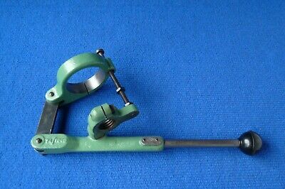
Following on from this thread here LINK I am in the process of making both a 1929 sensitive drilling attachment plus my own copy of the original Myford ML7 lever action tailstock attachment. I am reverse engineering the latter from pics of the Myford original on the internet.
The plan so far: (Can you tell I once worked in the drawing office for three months?)
(Sorry once again about sideways image. Can't seem to fix it. Perhaps the mods once again could fix it, pleeeze?)
But I am short of a few critical dimensions. What I can't measure from screen pictures is the thickness of the link that goes between the tailstock body clamp and the main hand lever. I am guessing it would be a piece of flat bar about 3/4" x 1/4" (20mm x6mm) but not sure.
Also, I am unsure what size the pivot bolts in that link would be, and the third main pivot bolt that connects the hand lever to the tailstock quill clamp. I am guessing 5/16" but not sure. And are they just plain bolts, or are they shoulder bolts with a plain shank and smaller diameter thread?
If some kind person who has an original Myford lever attachment could measure the link's width and thickness and those bolts and let me know I would be forever in your debt. So far it is the only remaining stumbling block.
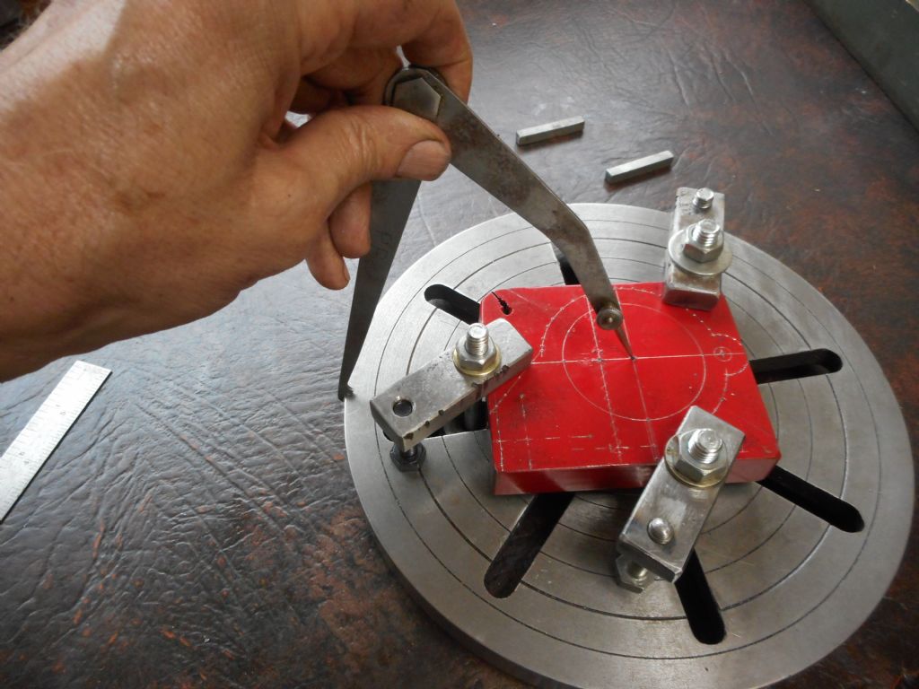
I have made a start already, digging a piece of 3/4" thick steel plate and similar alloy plate out of the scrap box and making up a couple of paper templates just as "proof of concept" so I know the material will be big enough. Turns out they are so have carried on making better drawings and laying out.
Both pieces are scabby old offcuts from the metal yard where they have cut these holes out of plate, hence the laser/plasma starting hole in each. The hex bar is to make the pivot bolts if they are not standard bolts.
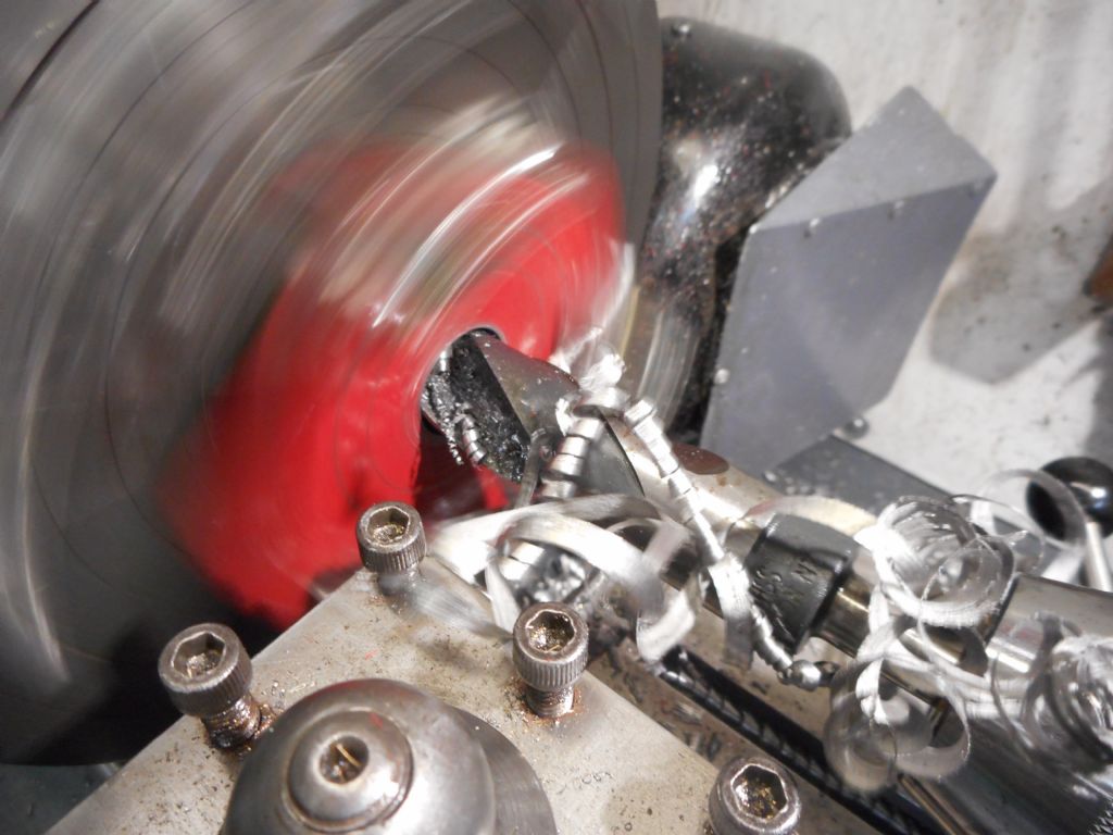
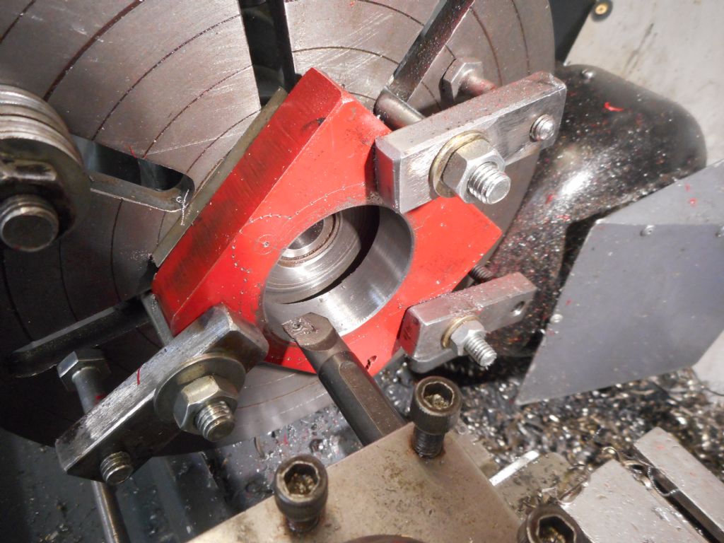
Will be a bit of working cutting these out on my new horizontal bandsaw and doing the rest in the lathe as I have no mill. Happy days.
Edited By Hopper on 13/03/2022 11:00:21
Mod edit: rotated photo
Edited By SillyOldDuffer on 13/03/2022 11:03:04