Unimat 3 Restoration

Advert

Unimat 3 Restoration

Home Forums Manual machine tools Unimat 3 Restoration

Viewing 25 posts - 1 through 25 (of 42 total)
  • Author
    Posts
  • #568346
    Graham Meek
    Participant
      @grahammeek88282

      I had a visitor to the workshop recently come bearing gifts. In the form of a much used Unimat 3 less original motor. The visitor said he had been given the machine some years ago and only came across it while clearing out the garden shed.

      If I could make use of it, then it was mine otherwise it was heading for the skip.

      After removing layers of swarf which had congealed with oil and formed a shellac work was started on stripping the machine. While everything was red with rust the bedways were in good order with some slight staining. Clearly the oil on the bedways had done its job in protecting them.

      After running a clock over the working surfaces of the Bed there as no more than 0.01 mm maximum wear.

      The tailstock working surfaces and the carriage working surfaces were not so good. while there was only about 0.05 mm wear the surface seemed to be filled with abrasive.

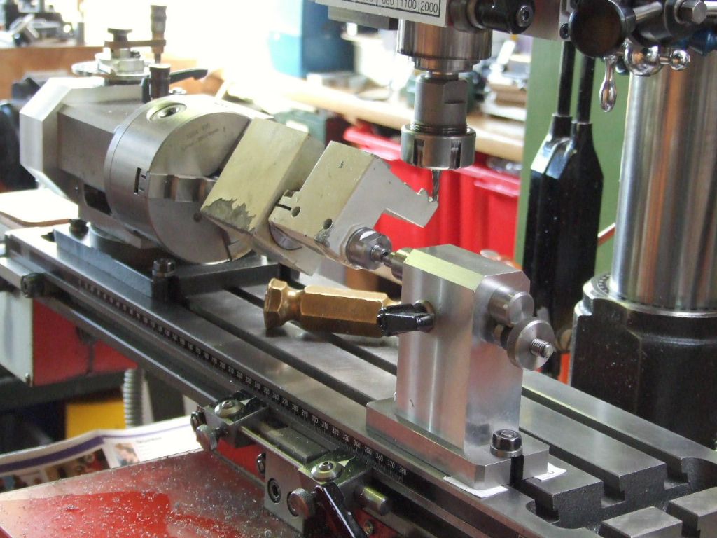
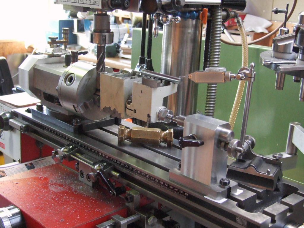
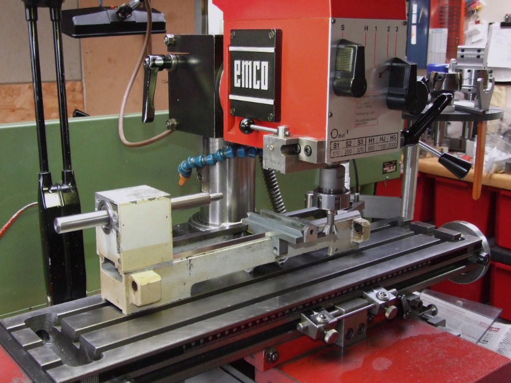
      Thus yesterday I made a start on machining the faces back to new. The Vee ways can present problems. Thus I opted for using the Dividing Head to guarantee an exact 90 degrees. Which also made machining the flat easy.

      machining second vee face.jpg

      checking height of flat surface.jpg

      Having the Headstock with an undamaged surface it was easy to establish what height the flat was relative to a roller in the Vee way. Machining the two items on a common mandrel ensured that alignment would be maintained.

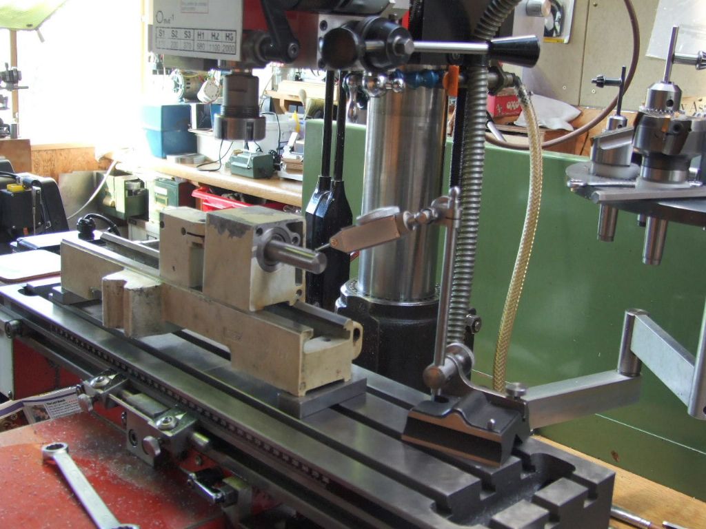
      clocking for parallelism 1.jpg

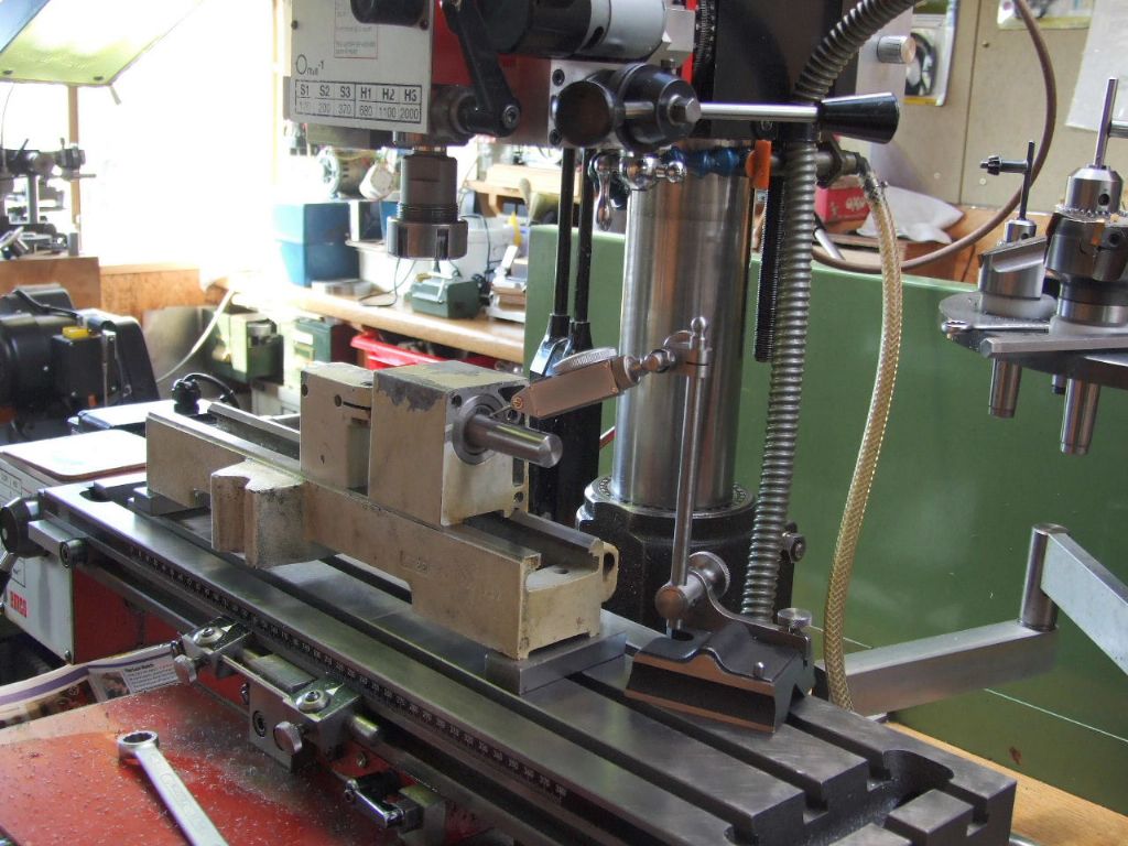
      clocking for parallelism 2.jpg

      Before the parts were removed from the mandrel a check was done on the Bed to ensure the mandrel was true or parallel to the bedways.

      The last operation on the Headstock was to put Helicoil inserts in the tapped holes which hold the motor mounting plate, apart from painting.

      More to follow.

      Regards

      Gray,

      Edited By Graham Meek on 26/10/2021 16:44:17

      Advert
      #14382
      Graham Meek
      Participant
        @grahammeek88282
        #568382
        Dave S
        Participant
          @daves59043

          Nice job.

          Did you take a minimal skim of the headstock and tailstock? (Assume you did)

          Dave

          #568456
          Graham Meek
          Participant
            @grahammeek88282

            Hi Dave,

            The Vee's on the tailstock were the worst, but only required 0.08 mm off each face. The Flat required more due to the geometry, but this was in the region of 0.125/0.15 mm. Hard to say exactly as the "touch on" with the cutter would have accounted for something. Even though the cutter still initially left signs of the Felt Tip marker ink.

            I have started on the carriage and the new machined faces fit on the bed is as I would expect. The dovetails for the cross-slide will be next. Over 6 mm rollers there is 0.05 mm taper from the unworn part nearest the handle to the end nearest the motor.

            In essence it should have a slight cant towards the headstock, so that the machine faces concave. However the machine is also used for milling and this would make the X and Y axis not square to one another. I know I am splitting hairs as the cant will be in the order of 0.01 mm over 100 mm. This is the point where it can be put right, but which is right?, so I am still pondering on this one.

            Regards

            Gray,

            #568548
            Graham Meek
            Participant
              @grahammeek88282

              Well after much prevaricating I decided to set the lathe up with a slight cant. It amounted to a quarter of one division on my 0.01 mm clock.

              Running a further check over a hardened dowel pin on the un-worn portion of the Master dovetail on the cross-slide showed on error. Thus I concluded I must have hit on the original factory setting, first time round.

              set-up for machining dovetails.jpg

              While the machine was on the milling table I also cleaned up the front face of handwheel boss. Just in case I need a flat face to reference off at a later date and also to remove the wear. Swarf at sometime had been trapped there and produced anything but a good running surface.

              Regards

              Gray,

              #568553
              Dave S
              Participant
                @daves59043

                Looking good. Biggest improvement I made to my Unimat 4 was fitting brass gibs.

                Dave

                #568608
                Graham Meek
                Participant
                  @grahammeek88282

                  Hi Dave,

                  I have been pondering over what to use for the new Gib strips. One of the previous owners had overtightened the adjusting screw and split the Moulded Glass reinforced plastic Gibs. My first thoughts were for steel, as the Taper Turning main body is made of steel. Tufnol also came to mind, but given you have had a good experience with Brass I might opt for this material.

                  Regards

                  Gray,

                  #568614
                  Kiwi Bloke
                  Participant
                    @kiwibloke62605

                    I'm sure brass would be good: it has a fine pedigree in instrument slides. Tufnol came to my mind, too. Perhaps Paxolin would be good, also. I'm a bit suspicious that glass-filled plastics are abrasive, once the surface layer, which seems to contain relatively less glass, starts wearing.

                    #568656
                    Graham Meek
                    Participant
                      @grahammeek88282

                      I have made Brass Gibs today and have so far fitted the cross-slide only. The cross-slide feels silky smooth now. However the taper turning attachment is going to need a bit more work. Holding the slide up to the light the Master dovetail on the toolpost is not matching that on the slideway.

                      Regards

                      Gray,

                      #568840
                      Howard Lewis
                      Participant
                        @howardlewis46836

                        You will probably finish up with a machine that is better than new, having painstakingly been fitted, assembled and aligned.

                        Nice work!

                        Howard

                        Edited By Howard Lewis on 29/10/2021 17:16:34

                        #568852
                        Graham Meek
                        Participant
                          @grahammeek88282

                          Thanks Howard,

                          You will probably be right on that score.

                          Having set the Taper Turning slide up on the mill this morning to skim the Master dovetail. I found whilst clocking the flat of the slideway that the slide had suffered some damage. In that the handle end was dipping away by about 0.15 mm. Where the slideway was bolted to a slave cross-slide in the machine vice there was no deflection.

                          Using a small screw jack off the bottom face of the machine vice I was able to rectify the error. Just to be on the safe side I machined 0.025 mm off these faces as well.

                          It is not an easy part to rectify as the feedscrew is fixed in relationship to the dovetails. Luckily my 0.05 mm off the dovetail did not affect this alignment.

                          The damage was not restricted to the slideway. When I assembled the feedscrew the handwheel end was running out by about 0.15. A few judicial taps with the nylon mallet in the Maximat lathe chuck soon had this part running true.

                          All is now well with the slideways and I shall be moving on to make a new spindle and tailstock barrel. Apart from both parts being extremely rusty the threads to take the chucks have worn a lot.

                          Regards

                          Gray,

                          Edited By Graham Meek on 29/10/2021 18:24:17

                          Edited By Graham Meek on 29/10/2021 18:24:48

                          #568883
                          Dave S
                          Participant
                            @daves59043

                            Do you mean a taper turning attachment or the top slide add on?
                            Ive not seen a taper turning attachment (like on a larger lathe) for a Unimat, so that would be interesting.

                            Dave

                            #568923
                            Graham Meek
                            Participant
                              @grahammeek88282

                              Hi Dave,

                              This is where my memory plays tricks with me. I was convinced Emco called it a Taper Turning attachment, but on checking the Parts List it is indeed referred to as the Top Slide. Which is what I would normally call this part of the lathe. Although it is referred to in other circles as the Compound Slide.

                              Sorry for building up your hopes on a Taper Turning attachment.

                              Regards

                              Gray,

                              #568938
                              JasonB
                              Moderator
                                @jasonb

                                The price lists and catalogue at the time called it "Top slide for Taper Turning". cost £27.00 in 1984

                                #569567
                                Graham Meek
                                Participant
                                  @grahammeek88282

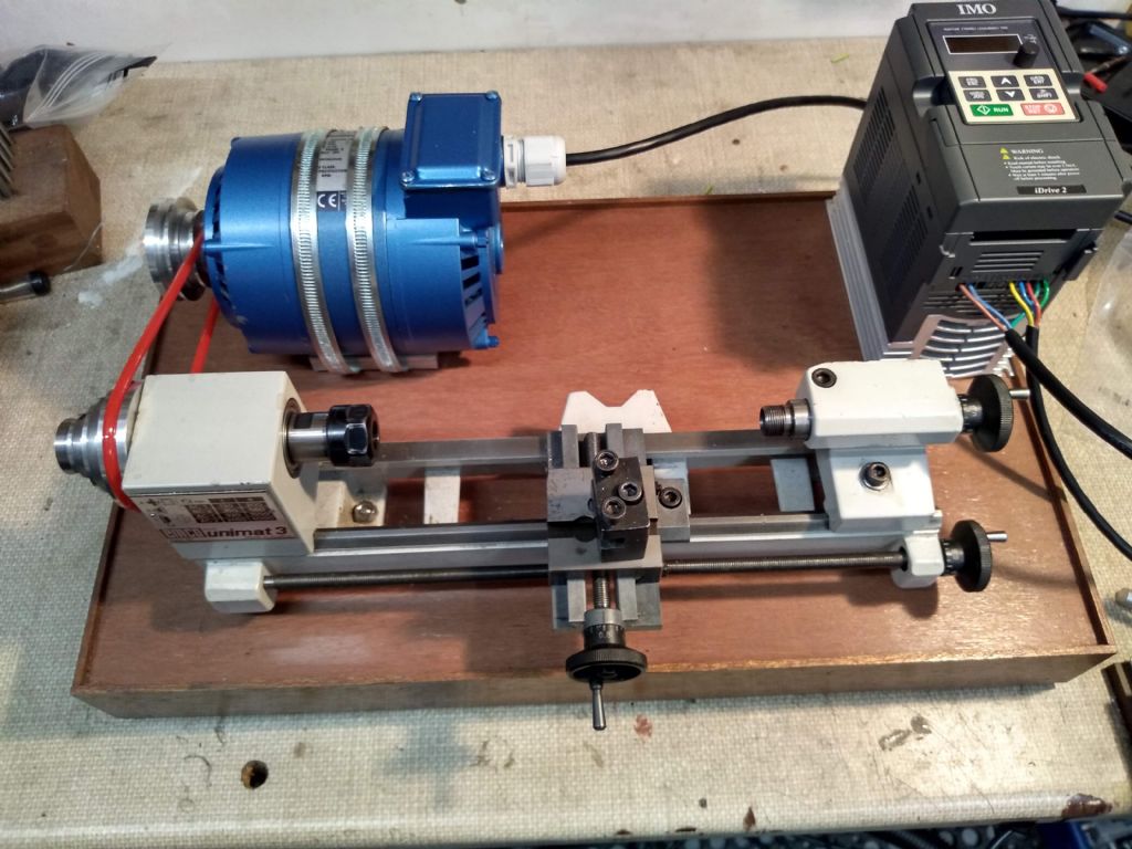
                                  On Monday the parts went to the Paint Shop, (aka the Summer House). This being warmer than workshop. I will be first to admit I am no good at paint spraying, but I am pleased with my efforts.unimat 3 back from the paint shop.jpg

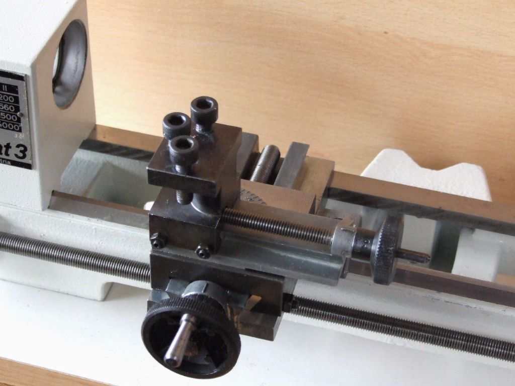
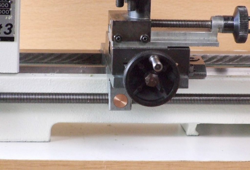
                                  I have also taken a photograph of the Cross-slide and Top-slide. The Brass Gib on the cross-slide is easy to spot.

                                  close-up showing one brass gib.jpg

                                  Lastly yesterday was spent on a salvage scheme for the Longitudinal feed nut. The original die-cast nut had worn quite considerably with 0,25 mm backlash. The new Phos Bronze Cylindrical nut has reduced the backlash to 0.05mm. Which is not bad considering it is the original feedscrew.

                                  salvage scheme on longitudinal feed nut.jpg

                                  Tomorrow hopefully I will make a start on the new Spindle and Tailstock Barrel.

                                  Regards

                                  Gray,

                                  #569568
                                  John Haine
                                  Participant
                                    @johnhaine32865

                                    Are you going to reproduce the original spindle? I made an ER16 spindle for mine using a parallel shank ER16 collet chuck, but it wasn't entirely satisfactory so have reverted to the original, but I would like to have a proper try at a complete spindle with ER16 taper and M22 thread.

                                    #569594
                                    Graham Meek
                                    Participant
                                      @grahammeek88282

                                      Hi John,

                                      I have acquired quite a bit of "shop soiled" original Emco tooling to go with this lathe, so I will be sticking with the standard spindle. I shall however be making the Spindle and Tailstock barrel from something a little more exotic. Which I hope will be more durable than the standard material.

                                      Regards

                                      Gray,

                                      #569603
                                      John Haine
                                      Participant
                                        @johnhaine32865

                                        Good plan! The original material does seem a little cheesy. Will you also stick with the horrible circlip arrangement to preload the bearings? On my ER16 spindle I went for an alternative using a

                                        img_20181127_172122697_hdr.jpg

                                        split collar on the left of the spindle which has a radial cut and clamp screw. Then I tensioned the dome washers with a long clamp between the headstock and pulleys (which also had a grub screw to lock on to the spindle), finally fitting the collar snug against the pulley and tightening the clamp.

                                        #569612
                                        Graham Meek
                                        Participant
                                          @grahammeek88282

                                          Hi John,

                                          I shall be sticking with the circlip arrangement as I have the parts for the Power Feed attachment, but currently no housing. The feed attachment needs the pulley groove in the original spindle. Hopefully Emco Austria will come up with a drawing for this part, so that I can make a new housing. Otherwise I shall be adding a variable DC drive to a home designed housing.

                                          Regards

                                          Gray,

                                          #569678
                                          John Olsen
                                          Participant
                                            @johnolsen79199

                                            I was hoping that you would put a rack feed on and convert the feed screw to a proper screw cutting setup with change wheels. I could measure up my fine feed if Emco don't come through.

                                            They need a better belt drive too, I mentioned on the current SL thread how I converted mine to toothed belt drive. Poly V would be another good way to go.

                                            John

                                            #569681
                                            JasonB
                                            Moderator
                                              @jasonb

                                              Gray if you need it I can pull my feed apart and give you sizes.

                                              If you did want to go down the ER spindle route a plain shank/ M14 adaptor would allow the Emco stuff to be used all be it with more overhang. I got one about a year ago and have used it a few times with the 4-jaw when I can't be bothered to change the 5C to 4-jaw on the warco. It's quite nice for small eccentrics etc

                                              #569688
                                              Graham Meek
                                              Participant
                                                @grahammeek88282

                                                Hi John and Jason,

                                                That is a very kind offer which I might have to take you up on.

                                                The man at Emco, Austria, did say he would have to go down to the basement and dig out the original drawings. As these are not on the current computer system in PDF format. If he cannot find them I will get back to you.

                                                Of what I remember from my Unimat days the belt drive shaft to the gearbox is at a slight angle.

                                                As regards the spindle change, I currently want to keep it standard. I have an ESX 25 collet attachment on the Compact 5 which suits my needs.

                                                I do need to make the Tommy bars for the 3-jawed chuck as these were not in the box, so if anyone to tell me the standard length of these I would be grateful.

                                                Regards

                                                Gray,

                                                #569717
                                                John Olsen
                                                Participant
                                                  @johnolsen79199

                                                  The standard tommy bars are 60mm long by 4mm diameter. So far as I can tell, the material is a bit better than mild steel, they can be bent with over enthusiastic use but normally are OK.

                                                  I would suggest though that you look through the old magazines, I had an article published about twenty or so years back about making C spanners to suit the Unimat. These are not hard to make, although the one for body of the three jaw does need an awkward cutout to clear the jaws. and they do end up making things a lot easier. There is one to suit the pulley end of the spindle, two for the three jaw, two for the collett chuck, and one to fit the milling attachment spindle. I made a lever actuated tailstock for mine too, ver useful.

                                                  I don't think the belt drive to the fine feed is at any sort of angle, I looked at mine just now and it all looks square. The body of the attachment is a funny shape but when it is on the machine the pulley shaft looks to be parallel to the base and square to the spindle. I've got a mini rotary table made out of one of those. Of course that belt is only an O ring, but it works OK.

                                                  John

                                                  #569720
                                                  JasonB
                                                  Moderator
                                                    @jasonb

                                                    The groove on the input to the fine feed is forward of the spindle ctr line so in that respect it the belt is at an angle. The side of the belt running down to the feed is fairly parallel to the back of the head but the returning side is quite angled due to the spindle groove being a lot nearer the head than the ctr line of the input shaft, this does help feed the belt though. 

                                                    Also twisted through 90 deg as the input shaft runs front to back.

                                                    Edited By JasonB on 04/11/2021 07:21:57

                                                    #569982
                                                    Graham Meek
                                                    Participant
                                                      @grahammeek88282

                                                      Hi John, and Jason,

                                                      Please excuse my tardy reply, the past two days have been a bit hectic.

                                                      Thanks for the info on the Tommy bars and the additional clarity on the Power feed attachment. I was convinced it was on a slight angle, that is my memory for you.

                                                      It is interesting that you made a rotary table out of the drive. Many years ago I made a dividing head using the same items. With its 40:1 ratio it was ideal, I may still have the original paper drawing of the main body. I will try and look it out.

                                                      Today I finished grinding the new Spindle and Tailstock barrel. The manufacture of which has been a bit of a trial in that the M14x1 gauge I made years ago left my threads oversize and I had to pick-up each thread and re-screw cut to size. The Moral here is to use the 3 wire system first, not last. The gauge is now in the scrap bin.

                                                      Hopefully I will have some more photographs over the next few days.

                                                      Regards

                                                      Gray,

                                                    Viewing 25 posts - 1 through 25 (of 42 total)
                                                    • Please log in to reply to this topic. Registering is free and easy using the links on the menu at the top of this page.

                                                    Advert

                                                    Latest Replies

                                                    Home Forums Manual machine tools Topics

                                                    Viewing 25 topics - 1 through 25 (of 25 total)
                                                    Viewing 25 topics - 1 through 25 (of 25 total)

                                                    View full reply list.

                                                    Advert