All things Beaver Mill

Advert

All things Beaver Mill

Home Forums Manual machine tools All things Beaver Mill

Viewing 25 posts - 1 through 25 (of 192 total)
  • Author
    Posts
  • #277443
    Robert James 3
    Participant
      @robertjames3

      Hi readers! I have started this thread for anything related to the Beaver Mills. If you have a question post it here, we won't accuse you of hijacking a thread. If you have a Beaver Mill and want to post pictures go for it. Thinking of buying one and have questions ask thm here. I'm on the road but with my next post I'll post some pictures. along with my model and serial numbers. Know something special about these Mills that is a little known fact chime in. Know someone who built these mills see if you can get them to chime in. As the title says this thread is all about the Beaver Mills. Thanks and enjoy!

      Advert
      #12862
      Robert James 3
      Participant
        @robertjames3

        An open thread for anyone owning or working on. a Beaver Mill

        #296757
        Guy Holmes
        Participant
          @guyholmes25250

          Hi, I'm new to all this I hate computers, I've been in engineering for 25 and always had a mill at home but always a chocolate machine so last year I bought a proper one as I call it, as I googled and came across this site I read the threads on beavers and a guy called robonthemoor saying how he was going to look at one in Leicester (where I am) and when he posted the pictures I realised the machine I bought was the one he based his thread on, whoops treading on toes and all that. It is an excellent machine but it came with its issues, I had to convert the whole machine from 415v to 240v that was everything, main drive, knee lift and on and on and on, it's up and running and I think it's far more sturdy than the Bridgeport. The seller at miles-Platts said it was a BT40 so I bought some tooling only for it to turn out to be an int40, I could do with a manual for the drive if anyone knows where I could get one.👍🏻

          #298313
          Bob McDougall
          Participant
            @bobmcdougall63250

            Hi, I have just bought a Beaver VBRP no. 3094/1. Guy, I would be interested on how you have done the motor conversion. The manual appears to show the windings in star configuration so I am hoping I can turn into delta for my 3 phase 240V inverter. If this isn't possible I wonder if a variable speed motor and speed controller of some kind might an option.

            The Beaver previous owner said he had changed the spindle bearings many years ago and they felt solid. But when the head at 90 degrees there appears to be some play. Someone who knows more about this is having a look tomorrow. I would be interested in the large user manual if a copy is available.

            My day job is in electronics so I'm planning to CNC the mill , Ive had one of the small aluminium cnc2030 machines and done some wood and stone so looking forward to getting the Beaver into metal.

            #298585
            Guy Holmes
            Participant
              @guyholmes25250

              When I converted the machine I basically stripped out every wire and switch, the only thing left was the 240 transformer and the 24v dc setup for the air and hydraulic setup, I started by replacing all the motors for single phase which was easy as they were all standard metric fittings and went in from there, the variable speed setup on mine is hydraulic centrifugal belt system much like the Bridgeport but with hydraulic cylinders controlling the belt placement, if you want pictures Bob I can send them to you if it helps ?

              #298624
              Bob McDougall
              Participant
                @bobmcdougall63250

                Guy, yes I am tempted to just strip the wiring completely and I i think I will replace with modern double insulated . its a 50 yr old machine, mice and rats . No idea what a centrifugal belt system is but Im young.Not sure if mine has a 240V transformer? I will post results. as far as Im aware it has all 3 motors in all, all are 3 phase 440v , main head 2 HP, coolant pump and X axis drive.

                The coolant pump is easily replaced with a 12V DC , The X axis I will change when I cnc it, the head 2HP is the one I need to try to find the star point, I have put the head over 90 degrees, and will pull the motor head offf next.

                My visiting expert confirmed the spindle had excessive play, the beaver instruction manual had a page which explained how to adjust the pre-load. , remove the quill nurled oilspigot, at the top of the quill , put an alan key through and loosen the top ring on the spindle, then leaving the alan key in turn the bottom of the spindle clockwise to tighten the pre-load. , I didnt try that.

                I dropped the quill last night and tried to tighten the top nut but it didnt make any difference to the spindle play 1/8 inch turn didnt make much difference. I will post some pics now I understand how to use Albums ! Doh.

                Had a finger accident when removing the quill ,the down leaver has a spring which spun the quill lever when the quill left the gear catch. I will post some pics

                #298661
                Robert James 3
                Participant
                  @robertjames3

                  I have had many things taking up my time and have not been able to work on my mill. I know the head needs attention. I would love to see your pictures. My head is bound up it does not feed manually or under power milling has to be done by raising the table.

                  #298675
                  Russ B
                  Participant
                    @russb

                    Bob and Guy, I have a copy of the manual, I've sent you a private message with my contact details.

                    Regards,

                    Russ

                    #298715
                    Bob McDougall
                    Participant
                      @bobmcdougall63250

                      Play in the spindle, Yes that would be because the upper bearing (middle?) was like it was filled with jelly beans. I dropped the spindle this morning. Watched bridgeport spindle removal , but the Beaver was slightly different, ,With the quill at its normal fully up position. the locking ring on the Quill end had two square recesses. each had a grub screw going vertically up into the quill which I loosened then unscrewed the ring anticlockwise. I locked the quill with the downfeed lock clamp. I had to use a screwdriver and small hammer to get the ring moving. Its a very fine thread and was maybe 20 turns, then the ring dropped slightly but didnt fall off. I thought I hadnt unscrewed it fully but I had.

                      Then like the bridgeport video I used the drawbar top tube to tap down , I just tapped the top of the drawbar and the spindle slowly dropped out , bearings and all, the drawbar went below the top and I had to use an extension, as it is now, ive dropped the spindle onto a wooden block on the two main bearings visible. I put my hands on the bottom one, felt ok, the top one wobbled like drunken sailor . There might be another bearing even further up , but I lost heart .When I bought this machine I looked the man in the eye and said, Is there anything I need to do to it . No.

                      So I need a new set of spindle bearings, any recomendations ? Much appreciated. img_0484.jpg

                      #298717
                      Hopper
                      Participant
                        @hopper

                        No need to lose heart. Bearings are a consumable item like brake pads and clutch plates in cars. Cheap enough and not too difficult to replace. So you should replace all of them while you have it apart. Best recommendation is to use good name brand bearings, not cheapo no-name bearings off the net or a discount store. They are too much of an unknown quantity. Try to get a good brand of bearings such as SKF, Timken, FAG or similar, or even the Japanese Naachi are very good. Your old bearings should have the standard code numbers on them that are the same across all brands, so you just look for bearings with that same number.

                        #298718
                        Mark Rand
                        Participant
                          @markrand96270

                          For the main bearings, I went for:-

                          these

                          For the top bearing I went for:-

                          this

                          You might as well replace all the bearings at the same time. The cost is quite reasonable.

                          I had ended up replacing all the bearings in the motor, quill and head in the course of my rebuild, but my machine hadn't been treated kindly.

                          I've got two 10" blanks cut to make a pair of poly-V pulleys to replace the originals, where a previous owner used a crowbar to move the belt, but I haven't got around to that just yet.

                          #298733
                          Guy Holmes
                          Participant
                            @guyholmes25250

                            My machine is totally different to all the pictures I find online, mine is the mill 5 model, the only thing I keep being told is it's newer than most and weighs just over 2 tons, the head on my machine is 400 kilos on its own and the bearings are around 120mm outside diameter. Anyone any wiser???

                            #298759
                            john fletcher 1
                            Participant
                              @johnfletcher1

                              Most motors can be refigured from star to delta, at the terminal block. If that is not possible you will have to dismantle the motor and locate a largish lump often at the non drive end, it will need cutting open and three extra leads brought out to the terminal box. Any rewind shop will do this for you for an hours pay, once done then use an inverter. There has been several very good article on this site converting motors from star to delta, with good clear pictures and other details. I've found coolant pumps can be easily converted to run on 240 volt single phase using a 4 micro farad capacitor, again it needs to be reconnected.I have altered pump motors for my friends, and all it needed to do was to alter the links in the terminal box a ten minute job.John

                              #298934
                              Bob McDougall
                              Participant
                                @bobmcdougall63250
                                Mark, thanks for the link, I note they are 15 degree bearings. My spindle bearings are marked FAG 7207B TVP 42T EL GERMANY . They come up as 40 degree angle . Also not sure if they were a matched pair , cant find an exact reference to the 42T EL marking. It sounds like a big difference between the angles.


                                Edited By Bob McDougall on 20/05/2017 12:25:58

                                #299766
                                Bob McDougall
                                Participant
                                  @bobmcdougall63250

                                  VBRP motor 2HP 240V conversion not possible

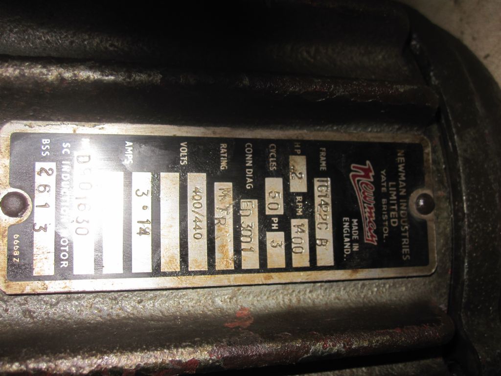
                                  Newman motor 1 The motor did not have a junction box and I hoped to find the star point by distmanteling but all I could see was lots of shellac and cloth tape.

                                  Beaver VBRP motor

                                  to dismantel I dropped the head 90 degrees, and undid the three retaining hex bolts which allowed the motor and triple pulley wheels to come out as one. The wires had to be cut. to split the motor casing the bearings are held by a plate inside both shells so I had to undo every nut and screw visible before the back came off. I couldnt get the key out of the shaft but it did fit through the housing, the front housing was on a lip and only came off by knocking it out after removing the rotor from the rear.

                                  Cant find the star point so will re-assemble and sell as whole and buy a 1HP 180V DC ex-treadmill motor for £50 on ebay and a 8A 180V DC controller for £50 . But I need to fix the bearings first,

                                  The spindle bearings which first took me here , Ive had the spindle looked at (thank you ) and it has some high spots like a bearing was put on crooked, now smoothed off with a stone. so Im optomistic.

                                  #299777
                                  John Stevenson 1
                                  Participant
                                    @johnstevenson1

                                    Bob save your money and hassle and take that stator to a decent motor rewinder and they can easily find the star point and bring it out safe ly in minutes

                                    #299879
                                    Bob McDougall
                                    Participant
                                      @bobmcdougall63250

                                      John i cant find any way to disagree, so yes i will , there is a rewinder 30 mins away, but the dc motor looks so lovely, and as a tinkerer i want to re-create. but you are right , I bet the rewinder will have it done in 5 minutes for £20.

                                      #300876
                                      Bob McDougall
                                      Participant
                                        @bobmcdougall63250

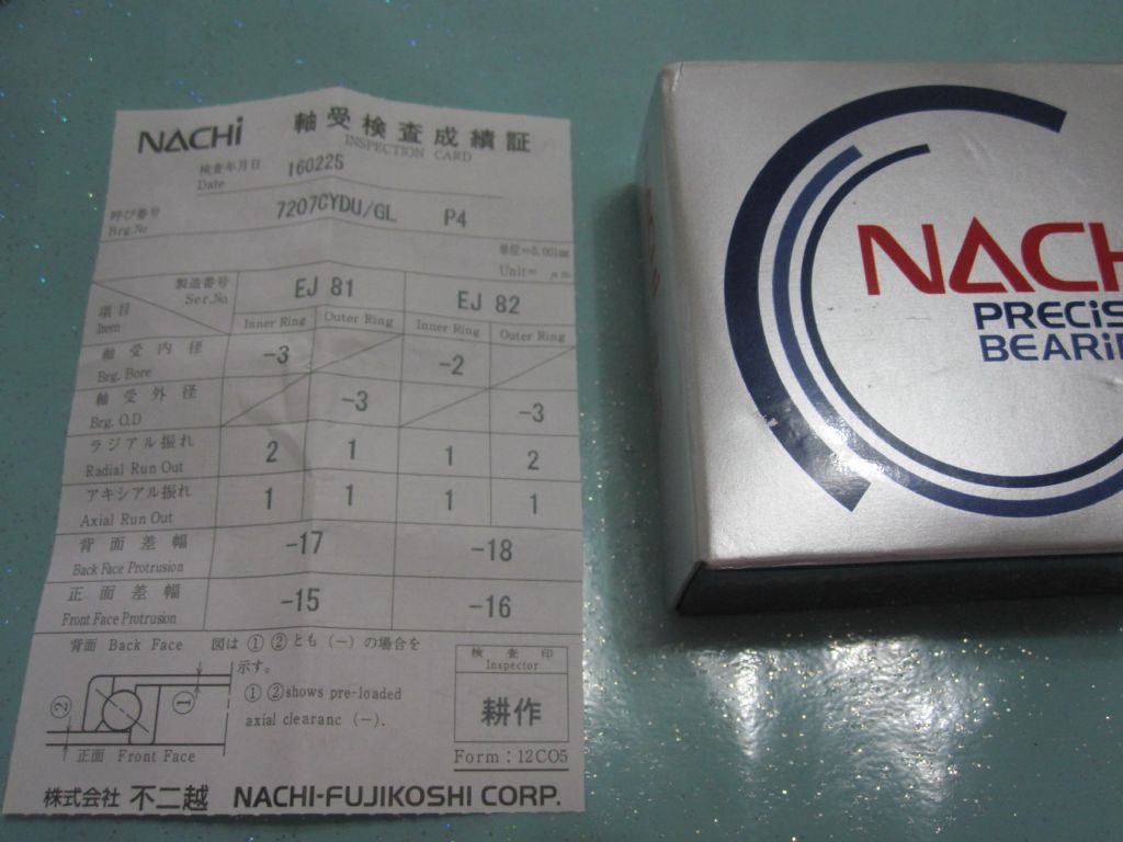
                                        Received the new spindle bearings today, nice to see they have a spec sheet. Watching you tube bridgeport spindle bearing replacement I noticed the bearings are thick side inward, DB style. Mine were thick side out when I removed them as my video shows ,DF style. I assume they were put in wrong and hence the looseness but I'm only going off that one video.

                                        Also found someone who worked at Newman motors to have a look at mine to see if the star point appears .

                                        img_0529.jpg

                                        #313455
                                        Mark Rand
                                        Participant
                                          @markrand96270

                                          When I replaced the bearings on my beaver spindle, I had (stupidly) assumed that the damage to the originals was mostly due to water ingress. Over time I'd got annoyed by the drumming noise from the head at top speed and assumed it was due to a previous a***h*le owner changing the speed with a crowbar on the belt rather than loosening the motor clamp. I'd recently noticed that vertical movement of the quill was slightly stiffer with the spindle in some positions.

                                          Today I needed to do some milling and distracted myself by putting an electric dial gauge (available at an Interweb auction site near you) on the side of the extended and clamped quill while rotating the spindle by hand. I measured 2.1 tenths of side to side movement on the quill every revolution. Might not sound much, but the quill is a fairly solid lump of metal…

                                          I took the quill out and measured the runout at The top end of the spindle. Five Thou!

                                          This caused me to remove the spindle from the quill and spend most of the day with a 2"x2.5" steel bar as a beam, two 10" G cramps for holding and bending and a couple of V-blocks for support. I left the bearings on the spindle because I'd risked enough damage by tapping the spindle out of the quill (whacking with a PLASTIC dead blow hammer).

                                          After several hours I got the total deflection down from 5 thou to half a thou and called it good enough. re-assembly was much easier than disassembly due to warming the quill up to 120°C in the oven. It just slips on over the bearings when warmed up.

                                          After putting the assembly back in the mill there was still some movement at the end of the quill as the spindle rotated. 10 micro inchescheeky. The mill, with spindle, isn't noticeably louder than just the belts and pulleys alone at top speed, so I'm happy that I've got that irritation fixed. There are a couple of 8" dia lumps of aluminium waiting for me to turn into Poly-V pulleys once I've convinced myself that the tiny belt the calculations suggest can really transmit 2hp.

                                          Tomorrow I might even get back to the job I meant to do today.smiley

                                          #359811
                                          Peter_H
                                          Participant
                                            @peter_h

                                            Bob McDougall : Did you ever find a definitive answer to whether the pair of 7207 bearings are fitted DB – thick side inward, or DF – thin side inward in the Beaver quill?. Also, if you had the 7206 angular contact bearing for the top (third) bearing and not the earlier deep groove, do you recall how it was fitted?. Ie, which way round and how it was seated and preloaded. Looking at what drawings I can find I can't really make any sense of it. I've almost reached the stage of removing and disassembling the spindle assembly, it's gnawing at me that much. It needs a new felt seal anyway so I may just strip it and draw up the parts if nobody knows the answers.

                                            TIA.

                                            #361089
                                            Bob McDougall
                                            Participant
                                              @bobmcdougall63250

                                              Hi Peter, I replaced the spindle bearings deep side in . but as you say there is very little confirmed data about the correct method. The upper bearing was a straight ball with no tilt . I have since sold the beaver as it was too large for me and bought a Downham mini jig borer for light precision milling. hope that helps.

                                              #361348
                                              Peter_H
                                              Participant
                                                @peter_h

                                                That helps a lot Bob, thak you. If it worked for you it will do me . It's annoying that there is so little documentation on the many variants. I'm pretty sure my top third bearing was a standard deep groove too. If it is angular contact then I just don't understand how it is supported and takes load.

                                                I would dearly love to make some better drawings for this mill, particularly the head, leadscrews and gearboxes. Does anybody know of a software package that can import a photo/scan, show it faint in the background and let you construct lines, circles, arcs etc over the top of it but as a separately saveable drawing file?. Maybe a DXF. Software eqivelant of tracing. At least you could end up with a drawing with fine, staright lines and maybe remove some ambiguities at the same time. Scaling would be useful, as would snap to a settable imperial or metric grid.

                                                Anybody know of such a program?. Preferably feeware

                                                #361356
                                                SillyOldDuffer
                                                Moderator
                                                  @sillyoldduffer
                                                  Posted by Peter_H on 09/07/2018 13:27:01:

                                                  I would dearly love to make some better drawings for this mill, particularly the head, leadscrews and gearboxes. Does anybody know of a software package that can import a photo/scan, show it faint in the background and let you construct lines, circles, arcs etc over the top of it but as a separately saveable drawing file?. Maybe a DXF. Software eqivelant of tracing. At least you could end up with a drawing with fine, staright lines and maybe remove some ambiguities at the same time. Scaling would be useful, as would snap to a settable imperial or metric grid.

                                                  Anybody know of such a program?. Preferably feeware

                                                  qcad does all that for about £30. (The free version is no longer available but there is an effective free fork called Librecad if you're on a budget.)

                                                  Both support layers (ie multiple transparent sheets stacked on top of each other that can be made visible or not) and a layer can be an image (photograph) or a CAD line drawing.

                                                  The tracing technique is easy enough: take a photo and import it into Layer 0. Then create Layer 1, and trace lines over the photographic image. Any number of layers can be added if that helps, for example to hold construction lines or text.

                                                  What makes tracing tricky is that photographs measure nothing and don't understand scale. They're just a good looking unreliable blob; no dimensional information plus lens distortions. A CAD package is the exact opposite – everything is specified precisely; the drawings are entirely informative.

                                                  So you can't do a straight tracing and automatically get good results, rather you have to translate the photo into sensible CAD dimensions using the image as a guide. Accuracy may not matter if you only want a cleaned up line drawing, but it's more work if you need accurate engineering drawings. For what it's worth, my preferred approach to this sort of job is to make a rough pencil drawing labelled with accurately measured dimensions and then use the dimensions to create a CAD drawing. I use qcad for 2D and Fusion360 for 3D.

                                                  As LibreCAD is free, give it a try and see how you get on.

                                                  Dave

                                                  #361367
                                                  Muzzer
                                                  Participant
                                                    @muzzer

                                                    Most CAD programs will allow you to import a scanned image and manipulate it (scale, opacity, colour, position etc), then create a 2D sketch on top. You don't need layers as such, as you can simply turn object visibility on and off or even delete the sketch when finished and save as another version.

                                                    If you are going to bother drawing it up, you'll probably want to enter the correct dimensions based on actual measurements once you've got the shapes right. Of course, you might then go the extra mile and extrude etc the sketches to create full 3D models…..

                                                    Like Dave, I make sketches with accurate dimensions then go straight to CAD. You'll struggle to correct the perspective etc on a photo of a large machine, so I'd give that step a miss.

                                                    Murray

                                                    #361371
                                                    Michael Gilligan
                                                    Participant
                                                      @michaelgilligan61133
                                                      Posted by SillyOldDuffer on 09/07/2018 15:03:10:

                                                      qcad does all that for about £30. (The free version is no longer available …

                                                      .

                                                      Dave,

                                                      You have me a little confused :

                                                      I have just refreshed my "QCAD"

                                                      QCAD 3.21.1

                                                      These packages contain QCAD, bundled with a free trial of QCAD Professional. The trial runs 15min at a time and can then be restarted. You can order QCAD Professional from our Online Shop and download the full version immediately. Alternatively, you can choose to remove the trial and use the free QCAD Community Edition instead.

                                                      **LINK**

                                                      https://www.qcad.org/en/download

                                                      .

                                                      MichaelG.

                                                    Viewing 25 posts - 1 through 25 (of 192 total)
                                                    • Please log in to reply to this topic. Registering is free and easy using the links on the menu at the top of this page.

                                                    Advert

                                                    Latest Replies

                                                    Home Forums Manual machine tools Topics

                                                    Viewing 25 topics - 1 through 25 (of 25 total)
                                                    Viewing 25 topics - 1 through 25 (of 25 total)

                                                    View full reply list.

                                                    Advert

                                                    Newsletter Sign-up