speed control pcb for Clarke CL300 lathe

Advert

speed control pcb for Clarke CL300 lathe

Home Forums Manual machine tools speed control pcb for Clarke CL300 lathe

Viewing 25 posts - 1 through 25 (of 226 total)
  • Author
    Posts
  • #50435
    Anthony Knights
    Participant
      @anthonyknights16741
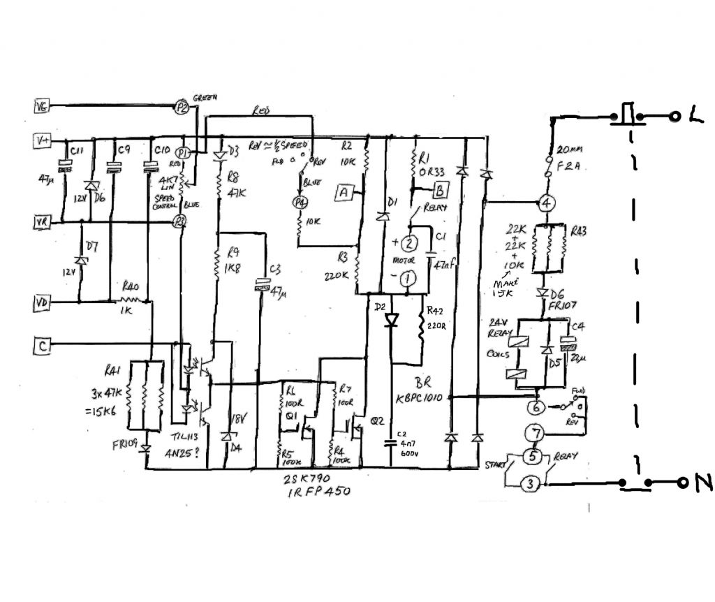
      Does anyone know a site where I can download a circuit diagram of the motor control PCB used on the Clarke CL300 lathe ?
      Advert
      #11657
      Anthony Knights
      Participant
        @anthonyknights16741
        #50439
        Pat Bravery
        Participant
          @patbravery
          Hello, Whilst I would like a circuit myself I have had a few problems with my CL300 control board. There are two types of board fitted as standard and it should have a label on, mine is a FC250J/230V which I beleive is the older type. The very likely cause of any problems are the mosfets IRFP 450, they are very cheap, I paid about £3 each on ebay. They both must be changed as they are matched.  I would be very interested in how you get on with it. Best regards Pat
          #50466
          Anthony Knights
          Participant
            @anthonyknights16741
            Thanks Pat. I’ve already found this information on the internet. The site recomended replacing MOSFETS with type STW20NK50Z, which I did. They blew as soon as the power was applied. The complete control box & motor are currently at Machine Marts service dept. Further research would indicate that the pinouts of the above MOSFETS are different from the original, hence the need for a diagram.
            #50503
            john swift 1
            Participant
              @johnswift1
               
              hi anthony
               
                                     i am working on a 10 year old board now
               
                  tracing the circuit  it looks like it was designed for europe and not the uk !
               
              one of the faults was due to over volts on C4   ,i have increased R41c 15k (was 10k)

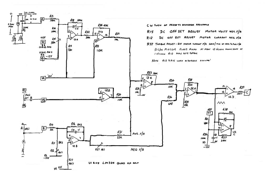
              the circuit is a work in progress   ( daughter board to follow then i can workout what the pots do !!!   )
               
              the last op amp on the daughter drives terminal C
               
              pwm +12v to – 12v  via 4.7k resistor


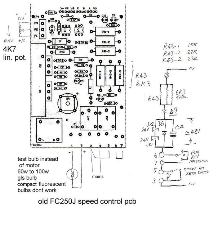
              you could use a 100W bulb as a dummy load in place of the motor

              just incase the motor is faulty

              #50529
              Anthony Knights
              Participant
                @anthonyknights16741
                Thanks for that John. I tried tracing the circuit but you have got further than me. There is a site with various links which you may find useful if you havent tried it already.
                 
                Regards Anthony.
                #50533
                Sub Mandrel
                Participant
                  @submandrel
                  Thanks John,
                   
                  Only three posts and you’ve already earnt the thanks of a host of mini lathe users, present and future
                   
                  Neil
                  #50647
                  john swift 1
                  Participant
                    @johnswift1

                    update to my FC250 circuit

                     i’ll rewire the fuseholder to the (new) live  terminal 3 and make terminal 4 the neutral
                    (having switches and /or fuses in the neutral are not a good thing to do )
                     
                     very soon i will have a working lathe
                    the last time i used a lathe and ground my own lathe tools was 28 years ago
                    it may take a little practice to get the parting off tool right again !!
                     
                     
                    #50650
                    Michael Cox 1
                    Participant
                      @michaelcox1
                      Hi John,
                      These circuit diagrams will be most useful.
                      Thank you.
                      Mike
                      #50652
                      Pat Bravery
                      Participant
                        @patbravery
                        Hello John, can I add my thanks for your info. Pat
                        #51548
                        Anthony Knights
                        Participant
                          @anthonyknights16741
                          Hi John,
                                         got my kit back from Macine Mart after (expensive ) repair and my CL300 is now running . I said “repair” but all they have done is replace the control PCB. I insisted they return the original faulty PCB, which they have done.(It is my property after all)
                          Thanks to you providing a circuit diagram, I am now in with a chance of repairing it so I have a spare available in case of another failure.
                          Thank you
                          best regards
                          Anthony (better known as TONY) Knights
                          #51595
                          john swift 1
                          Participant
                            @johnswift1
                            hi Tony
                                        the stw20nk50z has the same pin out as the original irfp450 and 2sk790 fets used on
                            the speed control
                            if cleaning and inspecting the motor has not cleared a fault  ??
                            the next thing to check is c1 (47nf) connected  across motor terminals 1 & 2 or dc1 & dc2 on
                            later boards
                             
                            you can test the board with a 100w gls bulb in live supply to limit any fault current
                            a short circuit motor or capacitor (c1) will not destroy the fets , the bulb will flash on and off instead
                            a 15w bulb in place  of the motor will prove you can control the output
                            i have tested using a 60w bulb in place of the motor but you only have control over the first 1/4 turn of the speed control before the 100w bulb in the supply limits the current !
                             
                            i very often use 100w bulbs when working on switch mode power supplies
                            the first time was to setup the power suppy in a tv , not wanting to damage any thing else or be x-rayed !
                            #51596
                            john swift 1
                            Participant
                              @johnswift1
                              hi Tony
                                          you might need to check diode d1 is not short circuited , its the largest diode on the board
                               
                               good luck
                               
                                                 john
                              #51712
                              Anthony Knights
                              Participant
                                @anthonyknights16741
                                Hi John
                                               have already found D1 to be short circuit. Somewhat ironic that when functioning it is there to protect the mosfets. I now need to search my “bits box” to find a suitable replacement. I still have a new pair of mosfets, so I live in hope
                                Thanks for the tip about using a dummy load.
                                 
                                 Regards  Tony
                                #51816
                                john swift 1
                                Participant
                                  @johnswift1
                                  hi tony
                                               the diode on my board  is a FR307   =   3A 1000V  fast recovery diode,
                                  you could use a UF5408 instead , a faster version of the 1N5408 you may have in your spares box
                                  instore or poundland type of shops are still selling 40 to 100 watt gls bulbs
                                  15w pigmy bulbs can be found in  the supermarkets –  bought one yesterday from tesco
                                  I now have confirmed with a 100w bulb in series with the  live supply , a 15w bulb instead of the motor and a spare 5K linear potentiometer
                                   you can check  that you  have full control of the dc output on your spare  board
                                  without disconnecting anything on your lathe
                                  the lucar connectors used are made of thinner than normal brass strip 
                                  resulting in a poor connection once  you have unplug them a few times


                                                       Regards   John 
                                  #54151
                                  Richard Edmonds
                                  Participant
                                    @richardedmonds33836
                                    Hi chaps, luckily I just found this site and am sure sombody here can help. Clarke 300 mini lathe, on start loud buzzing from control box and erratic speed control but does run in forward and reverse. Would describe as similar to pumping a car accelerator while driving. Can anybody advise as to what component might need replacing withing the PCB.
                                    Thanks for any extra advice on top of what I have read already.
                                     
                                    Regards
                                    Richard
                                    #54158
                                    Les Jones 1
                                    Participant
                                      @lesjones1
                                      Hi Richard,
                                                             The information you have given is not enough to identify the fault down to a single component. IF your controller board is the same as the schematic that John Swift has traced out then the only components that are likely to make the noise are the relays. This could be caused by  C4 going low in value or having an increased effective series resistance, or D5 or D6 or R43 being faulty. You would need to confirm that your board is the same as John’s schematic and if so that the noise is coming from the relays. I think you will need someone with electronics knowledge to assist you.
                                      Les.
                                      #54162
                                      john swift 1
                                      Participant
                                        @johnswift1
                                        Hi Richard ,
                                                         What control pcb  do you  have
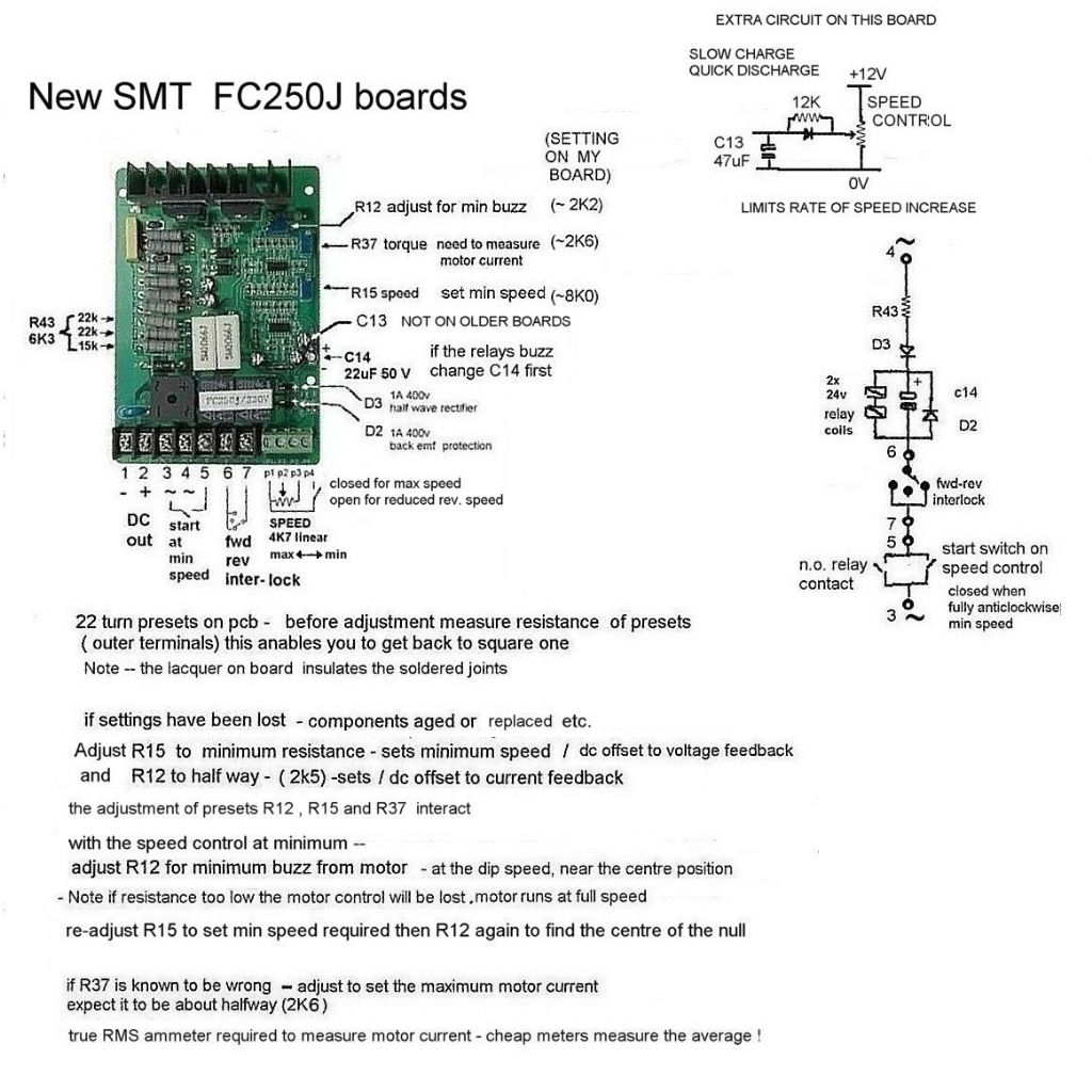
                                        the old type with the ICs on a small pcb or the new type with surface mount components all on one board ??
                                         
                                         first disconnect the motor to prove the noise is comming from the relays
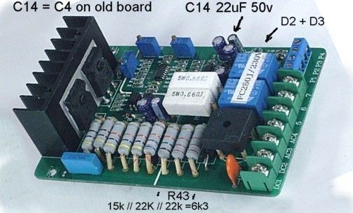
                                        If that is the case , measure R43 is 6K3 ( 2x 22K +15K in parallel  on 240v pcb)
                                        C4 (old pcb) / C14 ( new smt pcb) may measure as 22 uF( 50v)
                                         but the ESR may well be too high .
                                        on my board it was 7 ohms instead of less than 0.5 ohms.
                                         
                                        if the noise is from the motor
                                        first check the brushes are OK  – new ones are about 14 mm long
                                        and all connections are good i’ve found the lucar type of connectors used
                                        are a poor quality
                                         
                                        to prove the pcb is ok , use a gls bulb as a dummy load instead of the motor
                                        and check you have control with no erratic bursts of power
                                         
                                        If you think the board need ajdusting let me know what board you have and
                                        I’ll let you know how I set up my board


                                        #54171
                                        Richard Edmonds
                                        Participant
                                          @richardedmonds33836
                                          To John and Les, thanks guys I am busy till the weekend but will get into the thing then and figure out what is failing. I am indebted to you guys for your knowledge and practical assistance that will enable even me to repair this thing. Incidently John it is the older board so I think your drawing should help a lot.
                                          Thanks again guys i really do appreciate your help
                                           
                                          Richard
                                          #54173
                                          john swift 1
                                          Participant
                                            @johnswift1
                                            Hi Richard ,
                                             
                                            with the old type of board you should be able to repair it without any special rework tools.


                                            If you need more info just ask

                                            #54196
                                            Richard Edmonds
                                            Participant
                                              @richardedmonds33836
                                              Hi guys actually I was given the wrong info from Clarkes which is why I looked to this site. I actually have the board that John has in the photo posted to my original enquiry last tuesday. So it is in fact the new board and not the old board as advised by Clarkes and myself. So John sorry for that and yes I would be very interested in how you set up your board as suggested in tuesdays reply.
                                              I have to say though I am impressed with you chaps, I do not know what I would be doing without your help and I am very very gratefull to you all.
                                               
                                              Thanks and regards
                                              Richard
                                              #54197
                                              Les Jones 1
                                              Participant
                                                @lesjones1
                                                Hi John & Richard,
                                                                                     I suspect the board in the C300 mill is the FC350 board as opposed to the FC250. If the board has a transformer on it then it is probably the FC350.
                                                (If it is it could be the transformer that is buzzing.) There is some information on this board in the file section of the GrizHFMinimill Yahoo forum under “Grizzly G8689 mini-mill” You will have to join this group to read the file section. Here is a link to this group.
                                                 
                                                Les.
                                                #54205
                                                Les Jones 1
                                                Participant
                                                  @lesjones1
                                                  Hi again John & Richard,
                                                                                                 Forget my last message. For some reason I was thinking the problem was on a Clarke CMD300 mill when it is on a CL300 lathe. The mill has a larger motor which is why I thought the board would be the FC350. Seeing Anthony’s new posting on repeated postings made me realise my error.
                                                  Sorry for the confusion.
                                                  Les.
                                                  #54239
                                                  john swift 1
                                                  Participant
                                                    @johnswift1
                                                    Hi Rchard ,
                                                                       If you need to change the 22uF capacitor (C14)
                                                    maplin have a high temperature capacitor  cat number DT57M that will fit

                                                     
                                                    hope the notes make sence
                                                     
                                                    check the connections
                                                    lucar type connectors are not just held by the covers
                                                    a poor connection from P1 to P4 via the forward / reverse switch can give you rapid changes in speed.
                                                     
                                                     
                                                                             John
                                                     
                                                    #54268
                                                    Richard Edmonds
                                                    Participant
                                                      @richardedmonds33836
                                                      Right thanks John and Les, I got the thing out today and it is the relays that are causing the buzzing although I am not sure that was the reason for the erratic speed control. So I am now off to Maplin to get a few capacitors and try that first. The board is very much the same as Johns picture but is and SMD 250 AS opposed to SMT 250 so I do not know if it will make any difference. However the capacitor seems esay enough to change so will do that first. Will let you know when I ###### the whole thing up. Thanks guys and watchn this space
                                                      Regards
                                                      Richard
                                                    Viewing 25 posts - 1 through 25 (of 226 total)
                                                    • Please log in to reply to this topic. Registering is free and easy using the links on the menu at the top of this page.

                                                    Advert

                                                    Latest Replies

                                                    Home Forums Manual machine tools Topics

                                                    Viewing 25 topics - 1 through 25 (of 25 total)
                                                    Viewing 25 topics - 1 through 25 (of 25 total)

                                                    View full reply list.

                                                    Advert

                                                    Newsletter Sign-up