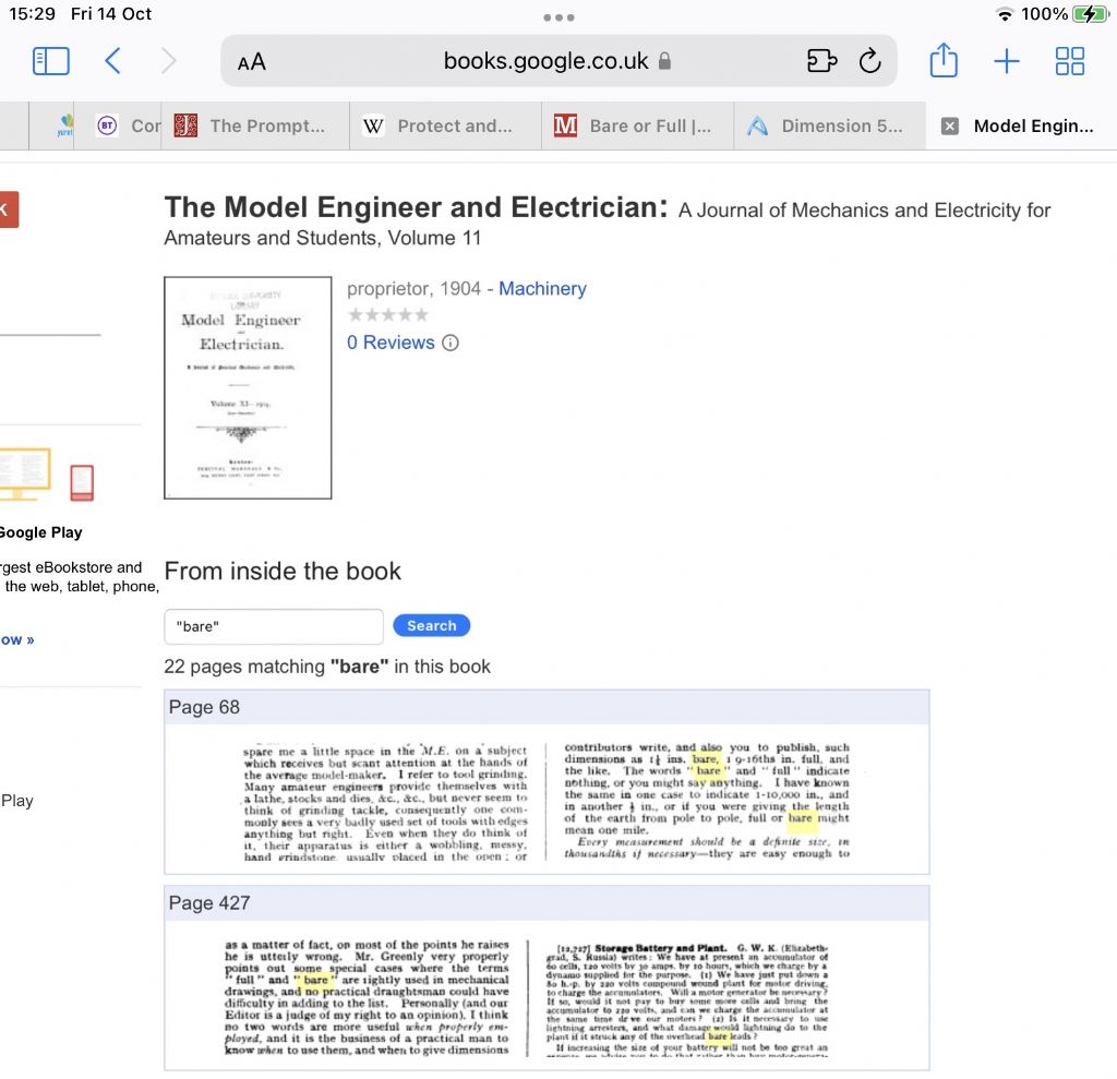
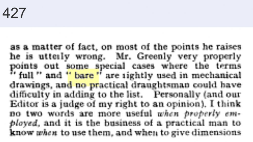
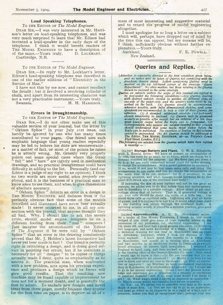
When I first started work in a mechanical design department the section leader, who had worked in the office since the early 1920's, quite often referred to "full or bare" dimensions when discussing a design. It was then left up to you to decide what that tolerance would be. As has been said, it harks back to the early days of manufacturing when precision measuring instruments were not always available.
For me it depends on what you are working on. In woodwork I would take it to be either one side or the other of the pencil line, depending on how blunt your pencil was. In metal work I would be be thinking more along the thickness of the engraved line on a good rule, certainly less than 1/64".
I have only really seen it used for linear dimensions, I don't think I have ever seen it used for diameters, which are usually described as "machine to a good fit", what ever that might be?
If you find it on a drawing, it is a case of looking to see how the relevant parts interact with each other and then deciding on your course of action. Model design drawings are not "tablets of stone". Unlike industrial design drawings, which require good reason and lots of paperwork to modify or change, our model designs can be modified to suit your particular requirements or machining limitations, provided that you understand how the design actually works.
I find that the use of some of these old-fashioned terms can be quite enlightening and sometimes amusing in these days of following a design rigidly to the letter. I like seeing them on old drawings, but that's just me.
Neil
Circlip.


