First Steel Parts off the KX1

Advert

First Steel Parts off the KX1

Home Forums Beginners questions First Steel Parts off the KX1

Viewing 16 posts - 1 through 16 (of 16 total)
  • Author
    Posts
  • #607906
    Steve Withnell
    Participant
      @stevewithnell34426

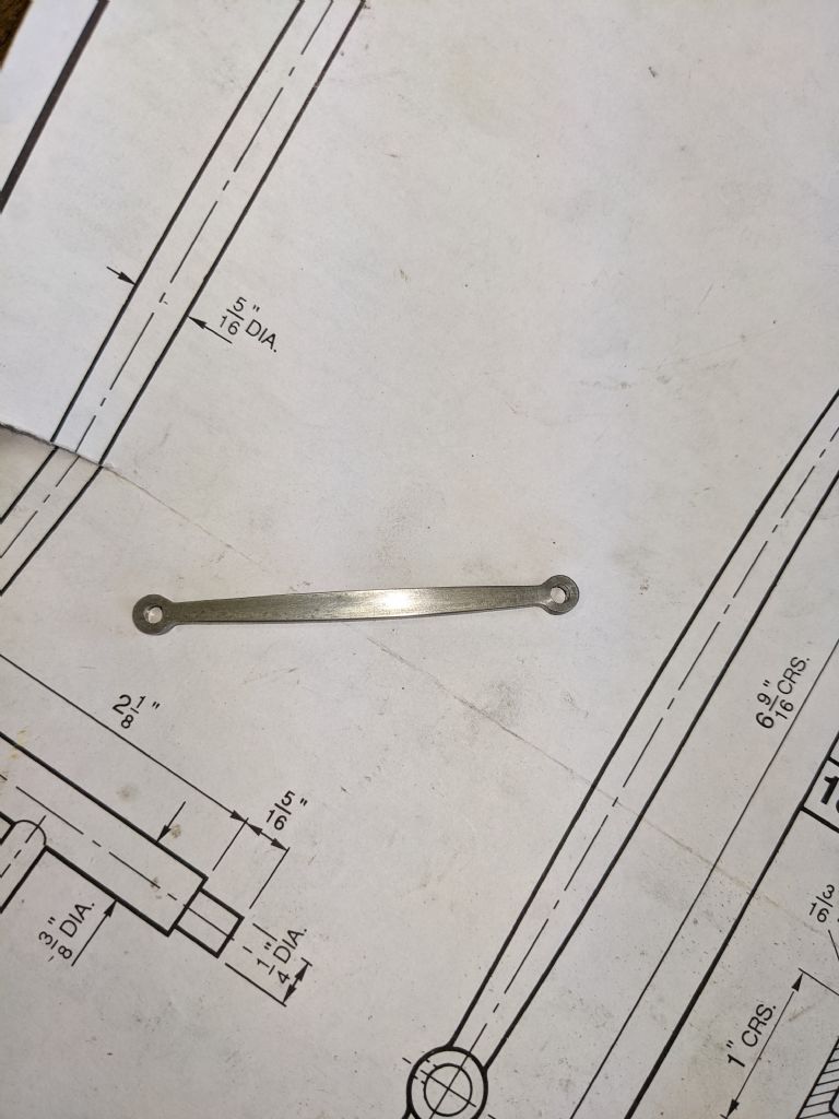
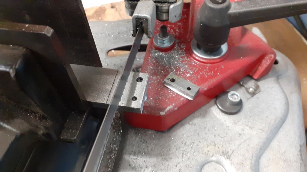
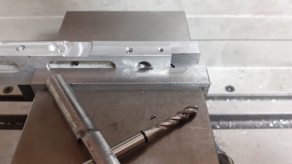
      And the first Steam parts. After a long lay off, the James Coombes is back from under the bench and back on it.

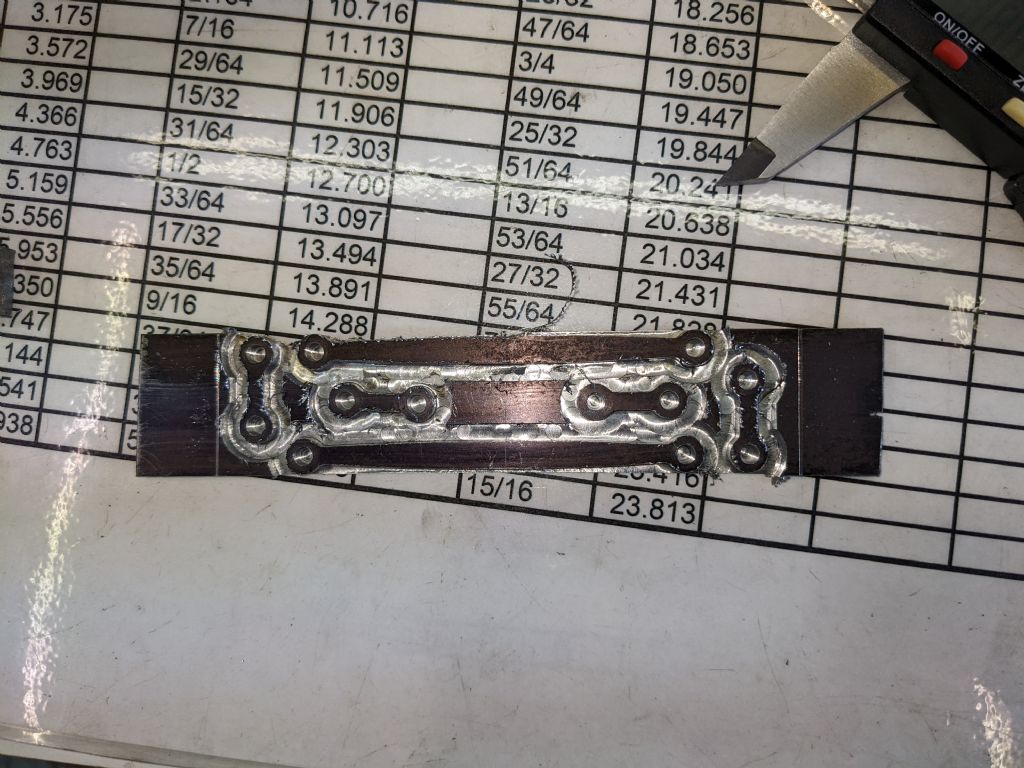
      Schoolboy error – the long rods are 1/8th thick and the short links are meant to be 1/4 inch thick. Nesting them together in 1/8th material wasn't the smartest thing I did yesterday…

      I didn't cut through the material and rely on tabs, but left 5 thou to hold all the components together. I did have some tabs, but wherever the machine cut a tab, I got a machining mark in the side of the part, I still trying to work that one out. I can't see where the cutter (3mm Titain coated carbide) deflection came from to blemish the part.

      Also used a slitting saw in the Warco mill, so getting all the skills warmed up

      nest.jpg

      link rod.jpg

      Advert
      #11279
      Steve Withnell
      Participant
        @stevewithnell34426
        #607913
        JasonB
        Moderator
          @jasonb

          It's often as the tool goes downwards at the end of the tab that the cut changes from the side to end cutting which causes the tool to deflect. You can reduce it by altering the tabs from straight sides to ramping up and down. Also set a final finish cut at full depth and set the others 0.1-0.2mm from the final profile.

          Parts like that I would tend to drill the holes first in smaller stock. Then put a bit of scrap aluminium into the CNC vice and have the machine drill two holes that can then be hand tapped. Screw the work to this block and use an adaptive cut at full depth leaving 0.3mm axial stock. Then do a contour again at full depth with 0.2 roughing and final 0.1mm pass Saves getting marks at the tabs and no material to file off where the tabs are or depth is not full height

          Edited By JasonB on 21/02/2023 07:25:25

          #607933
          old mart
          Participant
            @oldmart

            I'm surprised you had trouble with cutter deflection with a solid carbide, normally they would break. A short series one would be a better choice if the work is only going to be 1/4" thick. I play safe and only cut about 1/6 of the cutter diameter depth per pass.

            #607962
            Steve Withnell
            Participant
              @stevewithnell34426
              Posted by JasonB on 30/07/2022 18:42:19:

              Screw the work to this block and use an adaptive cut at full depth leaving 0.3mm axial stock.

              Thanks Jason, that's really helpful. What do you mean by "adaptive cut"? I'm using CUT2D/Mach3.

              Steve

              #607971
              Emgee
              Participant
                @emgee

                Steve

                Adaptive explained here on the Fusion360 site.

                **LINK**

                Emgee

                #607974
                Anonymous

                  I'm lazy and like to keep things simple. If the long rods are 1/8" thick make them from 1/8" material and if the short rods are 1/4" thick make them from 1/4" material. Make each part seperately.

                  I'd agree with mounting the parts using (CNC) pre-drilled holes. No need to faff about with tabs. In my experience tabs are a PITA, and take ages to clean up afterwards. With each blank mounted using screws in the holes only two simple 2.5D operations are needed. One, slot to full depth in steps appropriate to the diameter of the cutter with mixed climb/conventional milling for speed. For these small parts I'd leave 0.25mm for finishing. Two, a full depth finish pass with curved entry and exit paths, and use climb milling.

                  There is one caveat, I use flood coolant when machining steel which helps clear the swarf during the slotting operation. It also helps if the length of the blank is chosen so that the slot breaks out at the end, which also helps to clear swarf.

                  Andrew

                  #607976
                  JasonB
                  Moderator
                    @jasonb

                    It's a while since I used CUT2D, only played with that for a couple of weeks and found it too limiting for what I wanted to do. But if using that then select the profile cut and tick "do separate last cut" of say 0.2mm and also tick "3D" tabs which allows you to ramp up and back down rather than plunging.

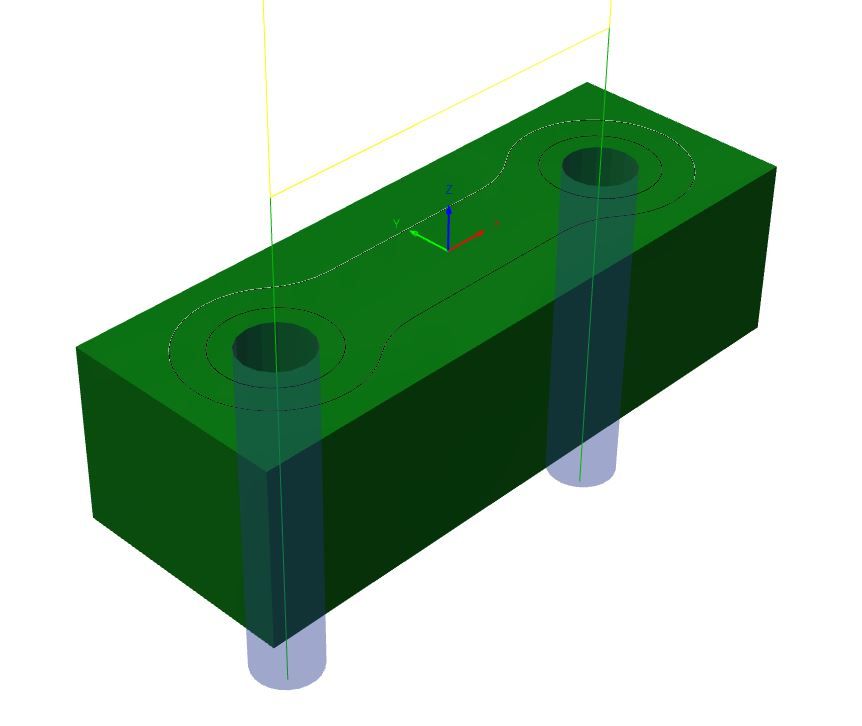
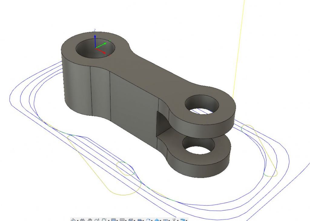
                    I tend to use the free version of Fusion 360. So would create three different paths. Firstly one that picks up the two holes at the ends and use that to locate the tapped holes in my tooling block. Don't alter X & Y after this then it ensures work is lined up.

                    holes.jpg

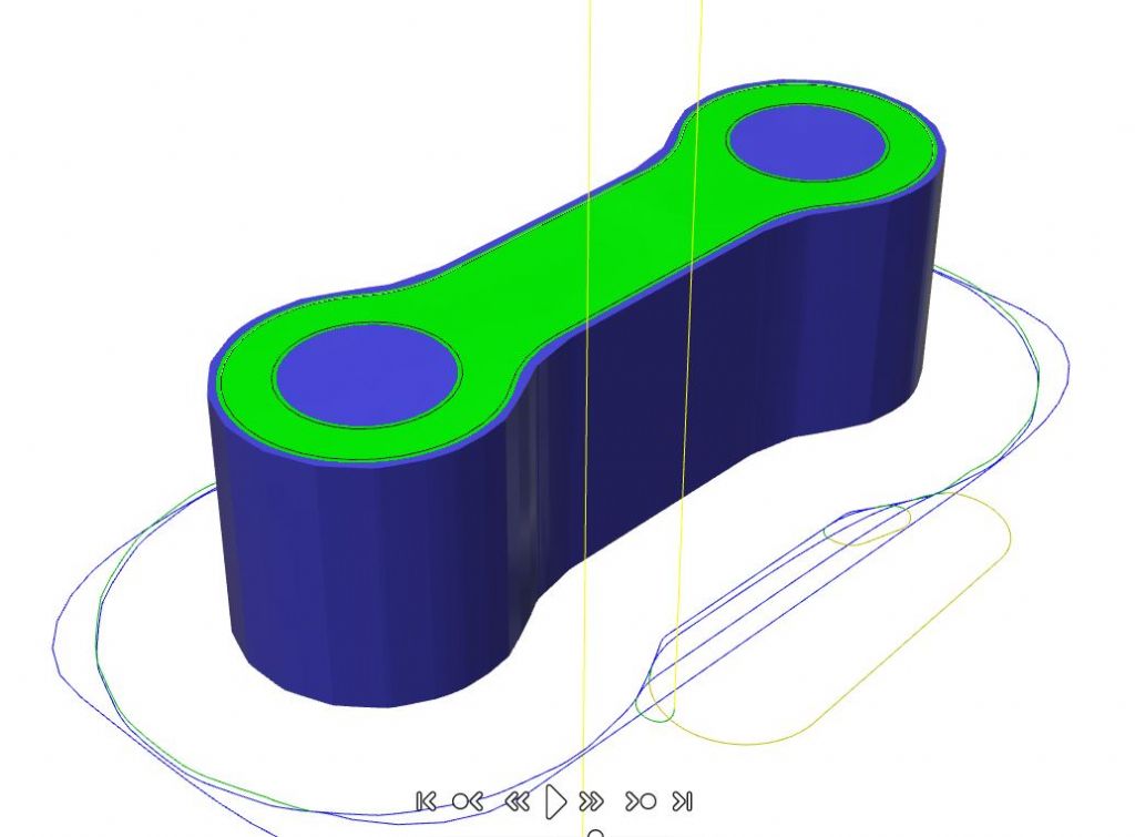
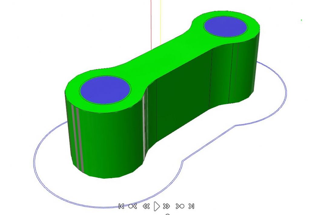
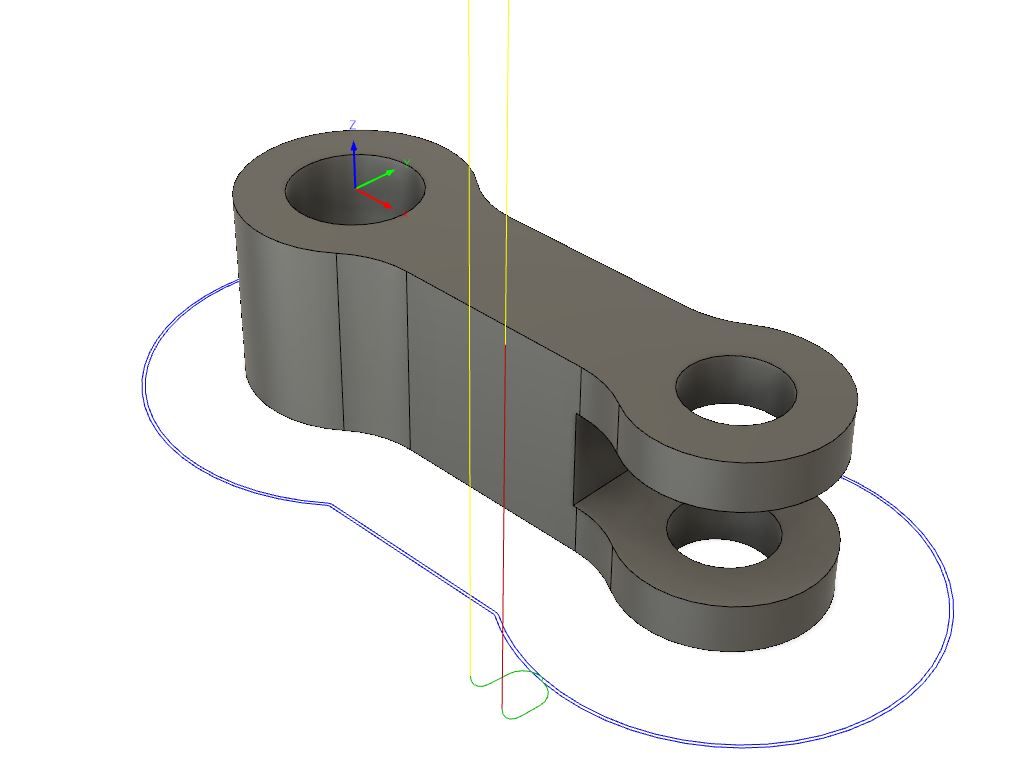
                    I would then do an adaptive path which is basically a roughing cut to take the work down to shape but leaving 0.3mm radial in this case but similar axial if it were a 3D job. Which gives a part something like this – you can see the curves are slightly facetted and the blue is material still to be cut. The thin blue line indicates the path that the ctr end of the cutter takes while cutting, yellow is when just moving about

                    adaptive cut.jpg

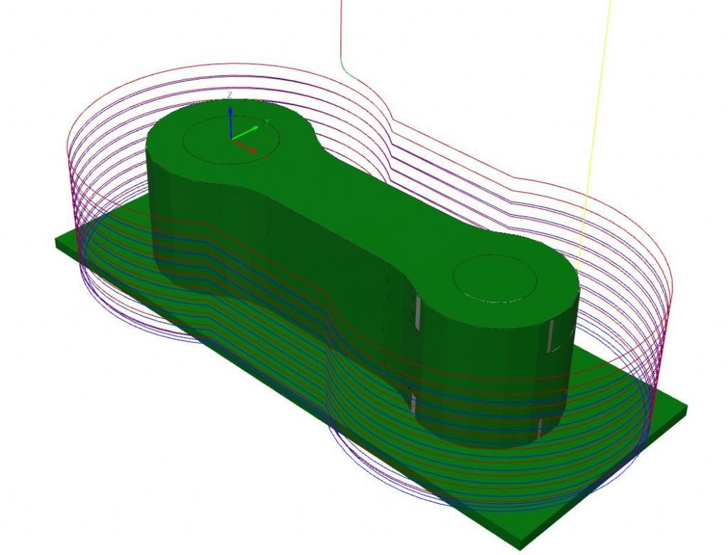
                    I would then do a contour path around the outside to finish the part. I usually do this as one roughing pass of 0.2mm and a final finish pass of 0.1mm which makes up the total 0.3mm I left on the adaptive. You can now see that the remaining blue waste has been removed and the curves are now a lot smoother

                    contour cut.jpg

                    That part drawing is what I used on my Victoria, this is the drilling and reaming of the links on the mamual mill before I screwed them to the CNC

                    And completed

                    All these cuts would be at full depth, I'm not keen on lots of shallow full width cuts as it just wears the end of the cutter, may as well use all the flute length that you paid for. Probably faster too particularly the 1/4" thick ones.

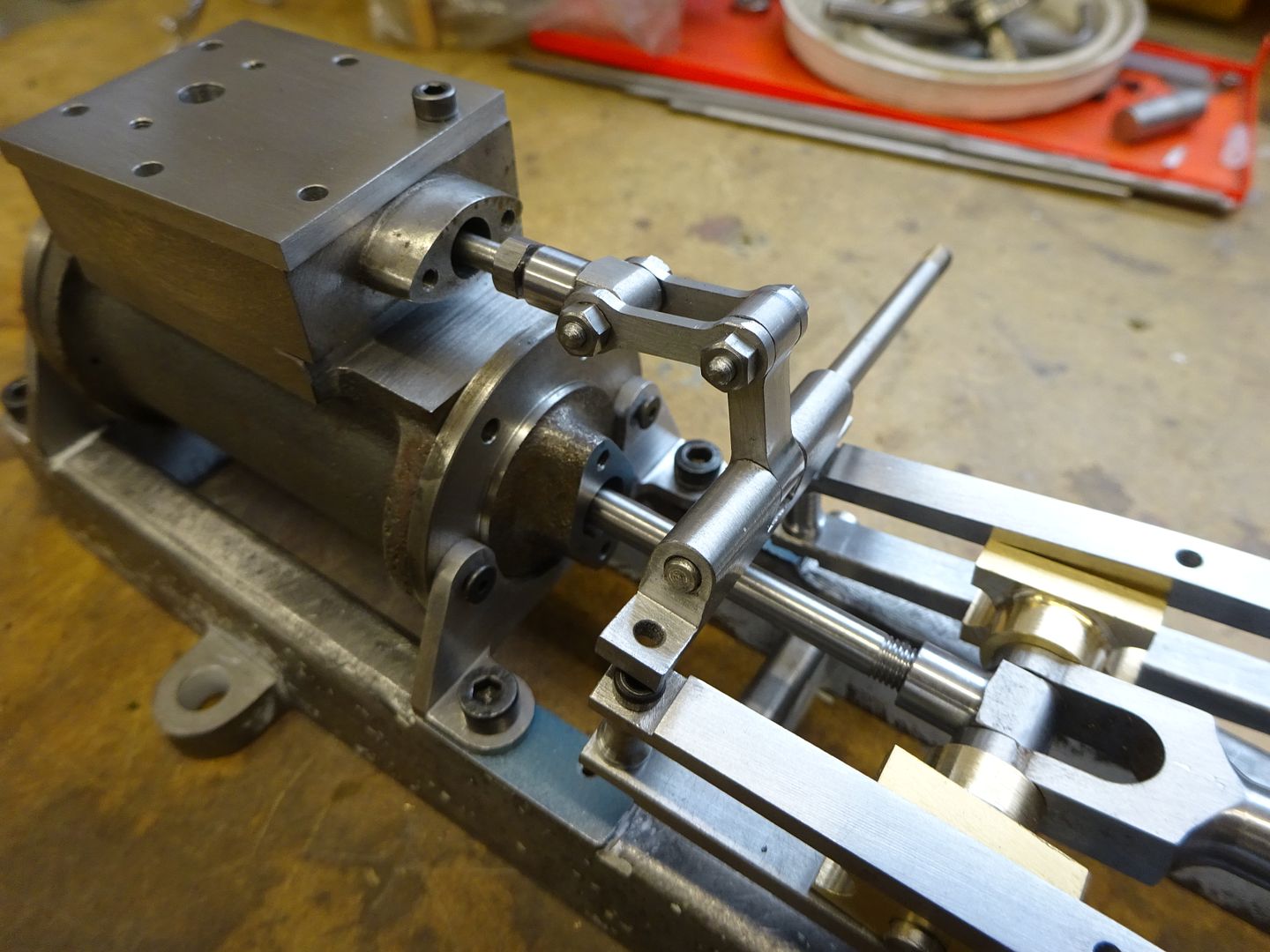
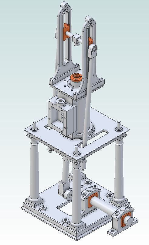
                    I've got my version of a James Coombes (minimal castings) on the screen at the moment, will complete the links and video one being cut if you give me a couple of days.

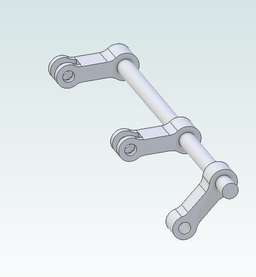
                    jc 3d.jpg

                    #608030
                    Nealeb
                    Participant
                      @nealeb

                      I'm curious about why you do an adaptive pass rather than contour with axial "material to leave" (and I'm also an F360 user for CAM). I typically – when the workpiece allows – drill first then use the holes for fixing and giving an uninterrupted profile but then do multiple contour passes with DOC according to cutter diameter (as someone has also noted above). Then a final pass or two at full depth.

                      I'm guessing that you do an adaptive pass because you are cutting the part from a block that is only a little oversize? I'm typically cutting a number of parts out of a larger piece of stock so I don't have to cut it up first. Always useful to compare notes!

                      #608046
                      JasonB
                      Moderator
                        @jasonb

                        It really comes down to each individual part and deciding what suits that. I do use the contour around the outside with screws or tabs for larger sheet metal type parts but with these links I went adaptive/contour for a few reasons.

                        1. The metal is supplied as 1/4 x 1/4 and 1/4 x 1/8 flat bar so only way to hold that and machine all the edge is by drilling (& reaming) first then screwing it down.

                        2. As said above I like to use all the cutters flutes

                        3. Adaptive tends to throw the chips clear where as a slot or contour in a larger sheet fills with swarf and needs clearing

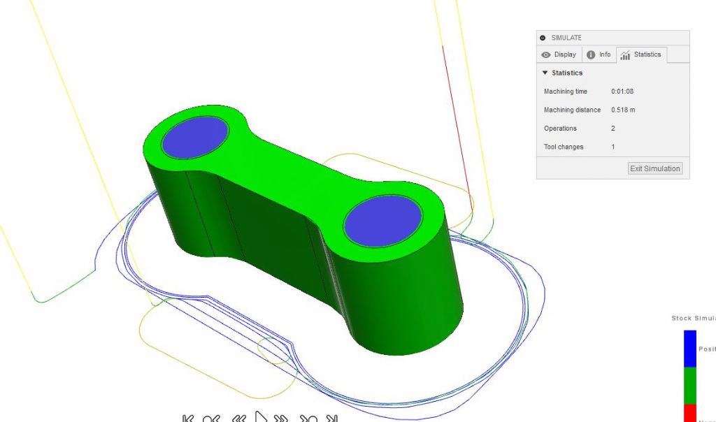
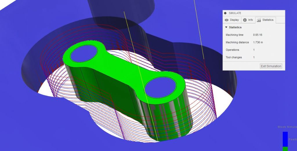
                        4. It's a lot faster to do the adaptive & finish contour than going round and round the part in vertical steps or a ramp . For example I would happily be able to run the adaptive & finish contours at a feed rate of 600mm/min and F360 says it will take me 1min 8secs per part. If I do it the other way then i would want to feed a bit slower say 400mm/min and as the tool has to travel a lot further the time goes up to 5mins 16 secs

                        5. For the 4 short links I only need to drill and tap two holes in my tooling plate. If cutting them all from one I would need 8 tapped holes which takes longer or if I used two hole sand moved the stock about there is a risk of off cuts catching the tool and possible damage.

                        6. Same as above really the waste material around the part also needs to be held so it does not start to move at the end so more holes to drill or another way found to constrain it.

                        link adaptive.jpg

                        link contour.jpg

                        #608118
                        Steve Withnell
                        Participant
                          @stevewithnell34426
                          Posted by JasonB on 31/07/2022 10:48:41:

                          It's a while since I used CUT2D, only played with that for a couple of weeks and found it too limiting for what I wanted to do. But if using that then select the profile cut and tick "do separate last cut" of say 0.2mm and also tick "3D" tabs which allows you to ramp up and back down rather than plunging.

                          I tend to use the free version of Fusion 360. So would create three different paths. Firstly one that picks up the two holes at the ends and use that to locate the tapped holes in my tooling block. Don't alter X & Y after this then it ensures work is lined up.

                          Thanks Jason – a lot of work there – much appreciated.

                          Now I've more time, I will go and have a more determined run at F360. CUT2D has been good to get started, but it's not going to support some of the more complex pieces I want to get to.

                          Regards

                          Steve

                          #608145
                          Nealeb
                          Participant
                            @nealeb

                            Coincidentally, last night I was doing the CAM stuff (F360) for another job. I need to cut some 4-bladed fans out of 20g steel, about 90mm across. I shall be using the fan's fixing holes with small wood screws into the spoil board (I use a lump of ply, resurfaced every so often, for this kind of work where depth of cut is not critical – profiling only) plus two more through the waste area – the rest of the waste will have the usual clamps on it. Then it's adaptive clearing plus finishing contour cut for the central hole, and contouring with a couple of step-downs for the external profile. I'm taking that easy because the blades will not be very firmly clamped so a deeper cut to start while there is still material in place to help hold them, and a final through cut with less depth. Then a finishing contour. Jason's point about the build-up of chips in the contouring groove is very valid but not too bad with this thin material. No tabs anywhere. I've become bored with the clean-up needed afterwards! Even with a gentle ramp and triangular tabs it's difficult to avoid some marking.

                            This CNC stuff needs a bit of thought ("yeah, you just get the machine to do it all, don't you?&quot but it beats the jigs and setups to do it manually.

                            #608146
                            Anonymous

                              Posted by Nealeb on 02/08/2022 10:03:33:

                              This CNC stuff needs a bit of thought…

                              +1

                              It requires a lot more thought, extra skills (CAD/CAM) and a detailed knowledge of how the cutting process works. Something that the naysayers are unable, or unwilling, to see.

                              Andrew

                              #608148
                              Martin Connelly
                              Participant
                                @martinconnelly55370

                                Andrew, I think some of the people who just want traditional machining think that being able to turn a handle up to a mark on a wheel is a great skill but are not thinking about all the pre and post work that goes into getting the part made. Most of this pre and post work is common to both CNC and non-CNC machining. I am talking about things like figuring out the order of making parts, preparing a piece of stock, making sure cutting tools are sorted out in advance, holding the part to work on it, cleaning and deburring the part after machining, checking it is correct… There are probably other things as well. Marking out to make a part takes a certain amount of skill but how many people nowadays don't bother marking out because they have a DRO? People using a DRO do not get the same sort of digs as people using CNC though.

                                The actual time a tool is cutting material on a machine is probably not too different for CNC and manual machining.

                                Martin C

                                #608220
                                JasonB
                                Moderator
                                  @jasonb

                                  I managed to get the short links drawn up for my version of the James Coombes so had a go at cutting them firstly with adaptive and then with the contour as though cutting out of a larger sheet.

                                  These are the links, two at 6mm thick and one at 5mm thick as I'm making mine in metric. They are all reamed to fit on a 4mm dia shaft and have reamed 3mm holes at the other end for pivot pins. Ends are 7mm & 6mm dia respectively with a 4mm wide central waist and holes are at 14mm ctrs, Internal fillet radius was set at 3.25mm so a 6mm cutter would not end up with too much engagement angle.

                                  jc links.jpg

                                  The above parts were drawn in Alibre and then I exported one of the thicker links as a .STEP file and opened in F360.

                                  Firstly the adaptive, details are much the same as mentioned previously removing all the metal with full height cuts (just passing below the bottom actually) with horizontal stepover of 0.6mm which is 10% of the 6mm 3-flute carbide cutter's diameter. F360 says run time is 51seconds with the cutter running at 5000rpm and feeding at 600mm/min.

                                  jc adaptive.jpg

                                  Next the final contour to remove the 0.3mm of material that was set to be left by the adaptive cut, same speeds and feeds and two loops around the work taking 0.2mm and then 0.1mm off. F360 says 31secs for this

                                  jc finish contour.jpg

                                  I then used the same imported part and did a cut as you may use if cutting from a larger sheet or piece of stock much like Steves original post but tweaked the height so the program thought it was the 5mm thick link. This one still cuts at 5000rpm but feeds at 400mm/min as I find using the full width of the cutter you can't go as fast. The cut ramps down as it goes round with a max stepdown of 0.6mm and that would be 6mm wide if cutting from a full sheet, mine was less as I used a smaller piece of stock. When the cutter gets to the bottom it then does one full height loop to take a 0.2mm finish cut all round. Time for this is 3.58 so would have been about 5mins for the thicker ones compared to about 1.20 for the adaptive % contour

                                  jc full contour.jpg

                                  Time to put it into practice.

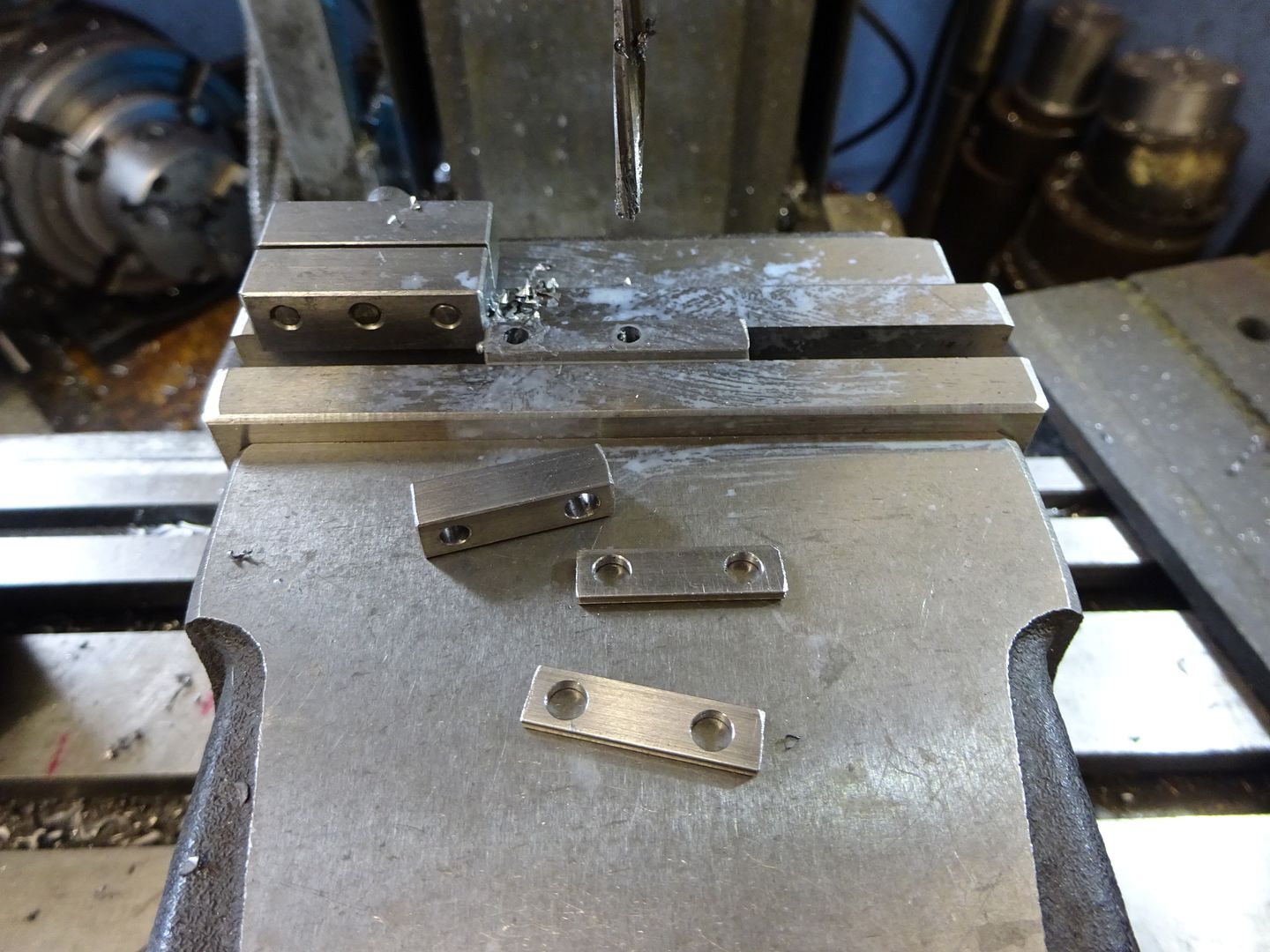
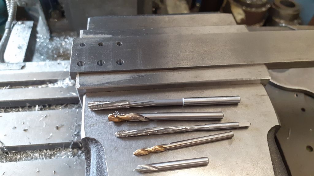
                                  I tend to find flat bar nicer to machine than sheet/plate so picked up a bit of 1" x 1/4" probably EN3 and held it in the manual mills vice to drill and ream the six holes on a simple pattern located with the DRO, could have used the CNC but not much in it time wise. Holes were spotted as I wanted good accuracy, then drilled with 2.8 & 3.8mm stub drills and finally reamed. Having it in the vice like this with no tooling plate below allowed the 3mm hand reamer to pass right through, not such an issue for the 4mm machine reamer – both run in the spindle.

                                  20220802_143723.jpg

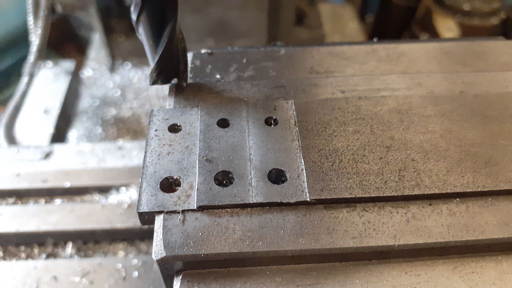
                                  A couple of quick passes with a 10mm HSS cutter had the 1/4" material reduced to 5mm and 6mm as needed.

                                  20220802_144214.jpg

                                  Then over to the Femi to chop the bits off the bar

                                  20220802_144411.jpg

                                  The KX3 was fired up and a bit of scrap aluminium held in the vice. Sometimes I just use the jog to drill these mounting holes but on this occasion used the CNC picking up the hole locations from the same F360 file and tapped the holes by hand. First hole had X&Y set as 0,0 which matched the larger hole position on the work which I had set as datum

                                  20220802_162437.jpg

                                  One of the 6mm pieces was screwed on and the start button pressed. and quickly completed. Swapping it over for the 5mm thick one the job took a lot longer, I could probably have had a steeper ramp angle that would have reduced the time a bit. At just before six mins you can see the final full height pass starts.

                                  Final parts feel burr free which is not bad as the cutter has done quite a bit of work and no difference in finish between the two options that I can see but I'll be sticking with the first adaptive option as it gets the job done and I'm not just putting a lot of wear on that first 0.6mm of the cutters flutes. All cuts were climb cutting.
                                  #608243
                                  Ian Johnson 1
                                  Participant
                                    @ianjohnson1

                                    Good to see another KX1 user Steve, and your parts turned out great.

                                    I started out using Cut2D which I found to be very intuitive and easy to use, then progressed onto Vcarve which has a few more useful gadgets like contouring and thread milling, 4th axis etc, it does everything I need and is just as easy to use as cut2d.

                                    IanJ

                                  Viewing 16 posts - 1 through 16 (of 16 total)
                                  • Please log in to reply to this topic. Registering is free and easy using the links on the menu at the top of this page.

                                  Advert

                                  Latest Replies

                                  Home Forums Beginners questions Topics

                                  Viewing 25 topics - 1 through 25 (of 25 total)
                                  Viewing 25 topics - 1 through 25 (of 25 total)

                                  View full reply list.

                                  Advert

                                  Newsletter Sign-up