Chuck & backplate problem

Advert

Chuck & backplate problem

Home Forums Beginners questions Chuck & backplate problem

Viewing 11 posts - 1 through 11 (of 11 total)
  • Author
    Posts
  • #11163
    Steve355
    Participant
      @steve355
      Advert
      #592031
      Steve355
      Participant
        @steve355

        Hi all

        Back again after a month or two messing with dark side woodwork things…

        I have a problem in that my chuck for my Zyto is broken. One of the operating screws is stripped, it seems. I would have a go at making another one, however, without a serviceable Chuck, that is pretty difficult.

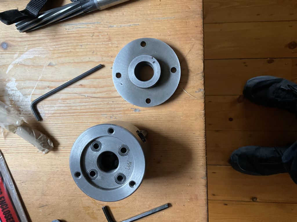
        so I bought another one, but guess what, it had a different number of backplate fixing holes (three instead of four). Other than this, the backplate is a good fit.

        getting backplates for a Zyto is really hard, it is a 7/8 inch 9 TPI thread. So I can’t easily get a new one. So I’m faced with a choice, drill the chuck to accept the old back plate, or drill the back plate to match the holes in the chuck.

        If I drill the chuck I can locate the position of the holes quite easily using the backplate and a centre punch. But I don’t want to drill holes in a brand-new chuck really, and it is probably hardened and so will be difficult to do. Also they will need tapping.

        I would much prefer to drill some new holes in the back plate. However, I can’t see how I would locate the holes for the drilling. Possibly on the vertical mill I suppose, if I can get accurate enough measurements. But I’m not really sure how to do that.

        Any thoughts or suggestions are welcome. See pic below.

        thanks

        Steve

        f2d20e1d-7afc-4f16-b537-3f4d8a3566d4.jpeg

        #592032
        JasonB
        Moderator
          @jasonb

          Your chuck should give the bolt hole pcd, some careful marking out will get your holes in the backplate positions. They are usually quite generous holes so so the screws will have some wiggle room. I'm assuming it is a threaded chuck not one where bolts go through from the front.

          #592033
          Perko7
          Participant
            @perko7

            I assume the photo shows the back of the backplate with the threaded boss that screws onto the spindle, and that the other face has a raised section that lines up with the recess in the back of the chuck. This is the register which provides the correct alignment for the chuck.

            Old school method would be to lay a sheet of paper over the back of the chuck and rub over with a charcoal stick or chalk stick or something similar. This will highlight the locations of the mounting holes and the recess for the register. Now lay the piece of paper over the backplate, line up the register recess, and centre pop through the paper for the 3 mounting holes.

            A modern alternative would be to lay the chuck backside down on the photocopier and take a copy of the back face, then go to step 2 above.

            The bolts are only there to hold the chuck on and stop it spinning, it's the register that provides the precise alignment, so a little inaccuracy in the position of the holes is not a major problem and they can be made oversize if needed.

            #592036
            Howard Lewis
            Participant
              @howardlewis46836

              7/8 x 9 tpi is 7/8 BSW. From you mention of screws, it sounds like a 4 jaw chuck, rather than a 3 jaw..

              If you fit the 4 hole backplate to the spindle, you then face it and turn the register to suit the new chuck, to ensure optimum alignment of the new chuck. It is unlikely that the register of the backplate will exactly match that of the new chuck, even if the face is absolutely square to the lathe axis.

              If you can make two studs with the same thread as the tappings in the new chuck, with pointed ends, you can mark the backplate to drill to match the new chuck.

              A 3 jaw will be quite adequate for this, if the new chuck is a 4 jaw.

              Paint the backplate with blue, roughly where the new through holes will be.

              Screw the two pointed studs into the chuck, far enough that they only just protrude.

              Use a bolt, or stud and nut, in one of the existing holes , to hold the backplate to the chuck with the register just engaged.

              The two pointed studs should mark the blue to show where the through clearance holes need to be drilled.

              Drill the new two holes, deburr and you should then be able to fit the backplate to the new chuck, using studs and nuts or hexagon head setscrews; as you wish.

              The freshly made face and register will provide the alignment, so the clearance holes can be a little oversize, if need be.

              HTH

              Howard

              #592081
              not done it yet
              Participant
                @notdoneityet

                Much as per Howard, but remember to size the spigot for fitting the chuck quite precisely. Some may say it doesn’t matter if the spigot is undersized – but the spigot is there for a reason! Done correctly, the two will be a very close fit, and re- positioning the chuck, when/if ever removed for cleaning, etc, will be a precise operation.

                Size the spigot (last finishing cut(s)) when the backplate is cold – it will become a loose fit if cut even only warm, let alone hot. Undercut the inner corner so that the chuck can seat completely to full depth, unless the chuck already has a chamfer to endure complete seating onto the spigot. Marking the orientation, with a dot punch mark, to make sure the chuck can be replaced in the same position, is also good practice.

                #592581
                Steve355
                Participant
                  @steve355

                  Thanks for the advice all.

                  Howard, unfortunately I don’t have a 3 jaw chuck (well, I have 2, but none with a Zyto backplate).

                  In the end I lashed up a “rotary table” from the VDH dividing head I picked up a while ago, but not got working properly yet. Dialled in a 120 degrees twice and it seemed to work.

                  Problem is, I’m getting about .002 runout on the chuck body. The spindle is Ok, as is the backplate, less than .001. But .002 at the chuck body. I have cleaned it up and it’s still there. It is there whether the screws are screwed in or not, so I don’t think it’s my new holes.

                  Being a 4 jaw independent chuck, am I right in thinking this doesn’t matter, as I will be indicating in workpieces?

                  Thanks

                  Steve

                  67c774bb-7cfb-45ad-9439-99f6597e7c71.jpeg

                  Edited By Steve355 on 02/04/2022 15:48:24

                  Edited By Steve355 on 02/04/2022 15:50:20

                  #592582
                  old mart
                  Participant
                    @oldmart

                    Radial runout in a four jaw independent does not matter, you have to compensate for that every time you put work in it. Check the runout of the chuck body face, that is more important, if that is not good, then a dead straight bar set to run perfectly near the jaws will have increased runout further away from the jaws.

                    #592586
                    not done it yet
                    Participant
                      @notdoneityet

                      Not sure why you would have the back plate mounted in a chuck (unless it was for drilling clearance holes using the 3 jaw as a dividing device). It will be operating on the spindle, so best is to set up/check it while attached to the spindle.

                      #592602
                      David-Clark 1
                      Participant
                        @david-clark1

                        Simples, been there, done that, wrote the article.

                        The article was published in Model Engineers Workshop so should be easy to find using online indexes. However, as I am using an IPad, I can’t read the google pdf index. Perhaps someone can post the article link in this thread?

                        Basically, clamp the chuck body to an angle plate or drill table by using a centre bolt and washer. Then line one of the chuck retaining holes up with the spindle. I used the plain end of a drill. Clamp the back plate to the back of the chuck and centre drill the hole and drill through.

                        Use a smaller pilot drill and then carefully drill through clearance for the chuck fixing screw making sure not to drill into the chuck body. Rotate the backplate and inert one of the screws into a spare hole through the backplate into the chuck. Drill the next hole and repeat for any remaining holes.

                        The chuck will be fired and ready to use. No marking out, no maths, just a simple drilling job.

                        The article was published in this forum so should be easy to find and link to.

                        Writer was DC1 and should be easy to find.

                        #592603
                        David-Clark 1
                        Participant
                          @david-clark1

                          Correction. The chuck will be fixed and ready to use.

                          f the holes are not equispaced, just line them up and do them individually.

                        Viewing 11 posts - 1 through 11 (of 11 total)
                        • Please log in to reply to this topic. Registering is free and easy using the links on the menu at the top of this page.

                        Advert

                        Latest Replies

                        Home Forums Beginners questions Topics

                        Viewing 25 topics - 1 through 25 (of 25 total)
                        Viewing 25 topics - 1 through 25 (of 25 total)

                        View full reply list.

                        Advert

                        Newsletter Sign-up