DRO—-How accurate

Advert

DRO—-How accurate

Home Forums Beginners questions DRO—-How accurate

Viewing 25 posts - 1 through 25 (of 47 total)
  • Author
    Posts
  • #11156
    Chris Mate
    Participant
      @chrismate31303

      Dro Quil/Spindle Mill

      Advert
      #591161
      Chris Mate
      Participant
        @chrismate31303

        This is just a friendly question looking for opinions/thoughts around this, after thinking a bit different about the subject: I think I May have identified an accuracy standoff……..

        —–Ills of accuracy locking the quil on a DRill/Mill…….

        With a Lathe the subject spins , the tool stand still. The ways are horizontal.

        With a Mill the tool spins, the object stands still compared normally.
        With a Mill the X/Y ways are horizontal, while the Z1/Z2 are vertical with some weight involved with Mill/Drills.

        DRO: Now if I fit a DRO to ether a Mill or Lathe way which is horizontal or vertical it will probably give an accurate representation of the position it represents and can ignore backlash.

        Now when it comes to connect a DRO to represent a mill's spindle height, is impossible seeing the spindle is spinning. The nearest you will get to the spindle is the Quil. Now the further you are mounted from the centre of the spindle the more an ignorable FLT in spindle from centre perspective will be amplified as you go further away with your mount, and this may go up or down measuring with a dial indicator or DRO fitted to quil, which can confuse you.

        Now today I went futher with my mill experimentation with dial indicator and and trying to read the spindle movement.

        So I fit an extra dial test indicator from below(Vice) measuring at the center of the spindle, not the quil. Now when operating the mill, this is of course not possible to do, because theres going to be a cutter in operation at that position.

        –SO I found that if I adjust the fine adjustment handwheel, If I adjust it down say 0.01mm and lock the quil, it everytime stay there, if theres a FLT, I cannot see it with this dial test indicator.
        —-However—-
        –For the same action, my other dial indicator mounted, I would say at least much more sturdy that any flex/arm type of magnetic dial indicator holder.
        Now think about this, while I know know the fine adjustment does not influence the spindle movemet(Just do not mess with it and then unlock the quil, it will move the spindle)….This indicator may or may not stay in the same place if I just unlock/lock the quil….

        So I want you to think about this situation….
        1-I cannot trust thr fine adjustment indicator by factory, but I can trust as log as I move it foreward only(Cut deeper and deeper), I cannot trust my dial indicator linked up to the quil.
        2-So I have a standoff here….

        So from all this in concideration, the fact you cannot mount anything to measure to the spindle directly, do you think a DRO representing the spindle centre itself can ever be considred accurate to eliminate the backlash effect, so you can mill the depth you think you are milling without quessing to the end between cutter and part-?

        #591169
        bernard towers
        Participant
          @bernardtowers37738

          Sorry Chris Mate what is this all about?

          #591171
          Robert Atkinson 2
          Participant
            @robertatkinson2

            You can mount something to measure the spindle. A Linear Variable Differential Transformer (LVDT) connected to the drawbar. The core of an LVDT can rotate without affecting the accuracy. Not very practical for everday use and it needs a lot of head room above the mill.
            A no-rotable sensor could be connected to the drawbar via a bearing. A pull string sensor is one option. For small movements a DTI would do.

            Robert G8RPI

            #591172
            Nigel Graham 2
            Participant
              @nigelgraham2

              It may help if you tell us the machine make and model, or supply a photo, as there are two basic layouts of small milling-machine; and to show how your DRO is fitted.

              – One keeps the table at fixed height, on the machine's plinth, and raises / lowers the head.

              – The other is more like the industrial pattern with the table on a "knee" that can be raised and lowered.

              Both have a quill as well, but that is normally for drilling, not high-accuracy depth-milling.

              .

              The DRO's vertical axis may measure the movement of the quill, but usually is for the knee or the head..

              Not the spindle.

              This does depend on machine type and how the DRO is installed, of course. For example, my mill is a Myford VMC and I have fitted the Z-reader to measure the knee travel.

              Backlash is less of a problem with the Z-axis because the moving unit's weight tends to keep the same thread-flank in permanent engagement, but in any case a normal DRO's long and cross-travel detectors measure the table not the lead-screw.

              '

              Other than that I am really rather puzzled what you are asking, but To Mill to Depth accurately, using a DRO or handwheel dial:

              – If possible work with the quill fully raised, for maximum rigidity.

              – Use the head or knee control to approach the cutter tip to just touch the work. You can use a witness cut but a safer way, more likely to err on the side of shallow rather than over-depth, is to "glue" a slip of thin paper to the surface with oil, and bring the cutter down to just remove that.

              – Set the DRO's 'Z' reading or the elevating hand-wheel dial to 0.

              Now cut down from that 0 setting.

              #591182
              Mike Poole
              Participant
                @mikepoole82104

                I am not quite clear as to what the issue is that you are describing but a DRO should be attached so it measures the actual quill movement and unless their is a serious problem with the spindle bearings it should represent the cutter position. If the mill is a knee type mill then it is possible to have a scale measuring the knee movement and a scale measuring the quill movement, a summing module can be used to give the true position of the cutter in Z whether you move the quill or the knee. The same method applies even if the table is fixed and Z movement is effected by moving the head or the quill. I think most people will lock the quill for normal milling operations for maximising rigidity. For drilling it can be simpler to use the quill or boring work with the head at an angle will mean using the quill.

                Mike

                #591184
                Hopper
                Participant
                  @hopper

                  Easy peasy. Hold a ball bearing mounted on an arbor in the dpindle. The inner race will rotate eith the spindle. The outer race can be held still by the pressure from a dial indicator plunger which can measure running spindle movement. Compare that with your DRO and you can see any error between the two and make allowances.

                  But worrying about such precision on a milling machine is a waste of time. They are not a super precision machine. If you can get within a thou or two thats all you need.

                  #591206
                  JasonB
                  Moderator
                    @jasonb

                    I just leave my quill locked so that takes any movement due to locking out of the equasion

                    There is also the argument that on a lathe the DRO measures the carriage and cross slide position, put on a heavy cut and there will be some deflection so you may not take off as much as the DRO shows. People don't seem to have a problem with that either.

                    #591223
                    SillyOldDuffer
                    Moderator
                      @sillyoldduffer

                      Apologies if I've misunderstood what Chris is saying.

                      I come at this another way. I don't bother with the absolute position of the table (X,Y) or of the spindle (Z). Instead, I measure relative to the cutting edges of the tool.

                      Typically,

                      • I plonk a vice on the table without worrying about it's exact position, apart from making sure the jaws are aligned parallel with table. This is done with a DTI held in the spindle.
                      • I position the job in the vice, again not worrying about its exact position. The vice ensures alignment, and height is fixed by parallels or by vice features.
                      • A fixed point on the job is selected as a datum, from which the DRO is set to 0,0,0. Corners are convenient when the job is a flat plate:
                        • With an edge-finder in the spindle, the table is positioned to move the corner under the vertical axis and the DRO set to X=0 and Y=0. Thereafter all X,Y movements measured by the DRO take place relative to this reference. (Until it's convenient to work from a different datum on a complicated workpiece.)
                        • Z (Spindle) is different because changing the cutter on a manual machine requires the Z DRO to be reset again from a reference datum. I usually set Z=0 by tacking a piece of hand-rolled cigarette paper to the job at the datum with a dab of light oil, spinning the cutter slowly, and gently lowering the head/quill until it just whips the paper off. As cigarette paper is less than 0.02mm / 1thou thick, this is usually 'good-enough' to set the DRO Z=0. All Z movements with this particular cutter are then done relative to this DRO setting.

                      The process uses the DRO to move cutters relative to fixed references on the job. Doesn't matter what the quill and head do provided the operator knows where the cutter is relative to a datum, as understood by the DRO. If the cutter or table moves because of backlash, the DRO is still correct and the operator can trust it to reposition the job under the cutter.

                      The DRO can also be reset on a reference datum at any time to make sure accuracy is maintained: errors can accumulate! On a simple job, the DRO might be set once but anything remotely complicated will have several datums and much shifting between them.

                      In short, always locate the job under the spindle relative to a fixed point on the job, as touched by the tool, resetting X,Y and Z to new zeros as necessary.

                      Dave

                      #591225
                      Circlip
                      Participant
                        @circlip

                        Gerra Mic and a set of clapperlipers, the battery never runs out.

                        Regards Ian.

                        #591236
                        Baz
                        Participant
                          @baz89810

                          Blimey I’m still trying to work out what the question is, but DRO——how accurate? I can answer that, good enough for industry to use for the past 40 years so plenty good enough for chasing microns in your garden shed.

                          #591292
                          Neil Lickfold
                          Participant
                            @neillickfold44316

                            Most DRO mounts are not very rigid and are often just piece of ali plate screwed together and then that is to transfer the movement of the axis it is connected with. The very short plate to the machine is never an issue, but on some installs there is 3 or 4 pieces to connect. Once the axis is moving it will show where it went to. But just moving back and forwards a minimum amount , like +-0.1 on an indicator and then watch the DRO read out. Some installs can have 0.03 mm difference. Cast iron is a better choice because of its higher rigidity. Other option is to make the connection from a single piece of steel or cast iron.

                            #591308
                            Chris Mate
                            Participant
                              @chrismate31303

                              This is a ZAY705 ZX-45 Mill DRill setup…

                              Sorry for confusion, I am trying to illustrate that trying to tap the spindle up/down movement(Z2) is much different than the usual others like: I am trying to understand the differences trying to tap the movement.

                              Lathe:The spinning part don't slide but spin.(Chuck/Collet etc)

                              1-The apron movement along the bed(Horizontal) Not spinning.
                              2-Crosslide movent(Horizontal) Not spinning

                              Mill:The spinng part(Spindle can slide with help of the Quil)

                              1-The Quil/Spindle=Z2 Can move Vertical up/down.
                              ——-Spindle spinning. (Slide with Quil)…You cannot tap the spindle itself)
                              ——-Quil Not spinning. (Not spinning but can slide)-Vertically…You can tap the quil, with some consequences other than with the other horizontal types.

                              2-The Headstock=Z1 axis(Column) Not spinning.
                              3-The Bed/table X-Axis Slide horizontally.Not spinning.
                              3-The bed Table Y-Axis Slide horizontally. Not spinning.

                              I see a big difference trying to tap the movement from a Mill Spindle compared to tapping the movements of those sliding horizontally as well as the Mill/Drill headstock sliding vertically.

                              Just curious if you see my point(s)……….I never thought about this like this ever before untill recently.

                              #591311
                              Hopper
                              Participant
                                @hopper

                                So the spinning spindle will move the same amount as the non spinning quill it is mounted in. Plus or minus the negligible clearance in the ball bearings holding the spindle into the quill. One thou or less. Not enough to be of concern. Or if you have taper roller bearings that clearance will be zero. So how much the easily measured quill moves, the spinning spindle also moves.

                                Edited By Hopper on 23/03/2022 21:38:32

                                #591318
                                Pete Rimmer
                                Participant
                                  @peterimmer30576

                                  Put the DRO on the quill like the rest of the world and read the quill movement. If the spindle moves any differently in the vertical direction to the quill at all then the problem isn't with the DRO placement it's with the spindle bearings.

                                  #591326
                                  Chris Mate
                                  Participant
                                    @chrismate31303

                                    Maybe how I am trying to say something is confusing. I used 2x indicators at the same time.

                                    1-I have proved already with a another Dial Test Indicator in the vice clamed upwards to the spindle pressing on the spindle, that if I Lock-The-Quil, there is zero change in vertical position that I can see at .01mm type of Dial Test Indicator…This reading is constant at zero, does not matter how I move the quil up or down with the Fine-Adjustment. …So it seems the machine can cut accurate from the machine's spindle centrepoint perspective.

                                    2-However at the same time as I move the quil up or down, my fitted Dial Indicator does not always agree with the Dial-Test-Indicator, this one may or may not show up to .5mm difference. Now this can maybe only due to the quil moving sideways, and this Dial Indicator(Also .01mm) picking that up because its not pointed to the spindle centre.

                                    3-My argument is if I fit a DRO to quil it would be similar to how I fitted the Dial-Indicator and it may be inaccurate, in the sense it can mislead me trusting it——?

                                    Maybe a long time german machinist visit me next week, I will show him exactly what I see(Had discussed it with him on telephone, he did say he never use his quil adjustment), and hear his opinion on this. He has a knee mill.

                                    #591329
                                    Hopper
                                    Participant
                                      @hopper

                                      No idea what you are talking about now. Pictures needed to explain your problem. I am totally unclear on where you have the two dial indicators mounted and where they are measuring.

                                      Are you having problems with your mill not producing accurate work? If not, then you are probably overthinking the problem.

                                      Best to have your machinist friend look at it in person. It seems whatever your problem is, it is not commonly known about among the mill owners on here or one would have jumped in with a solution by now.

                                      #591336
                                      Pete Rimmer
                                      Participant
                                        @peterimmer30576

                                        Now it sounds like the quill is loose in the head. Chris, post a photo of how you have your dial gauges arranged.

                                        #591340
                                        Chris Mate
                                        Participant
                                          @chrismate31303

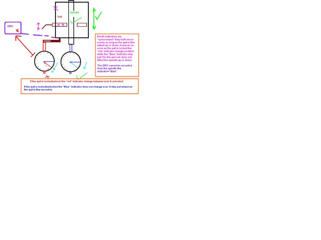
                                          Here is an illustration: This is about using the Fine Adjustment for quil/spindle.

                                          I can get the "Red" indicator close by repeatedly locking unlocking the quil, but if I unlock it, the Red indicator sags away from locked reading…If I actually mill this is worse.

                                          I am pretty sure one can trust the spindle behaviour when quil is locked and you mill, but that is not where I can mount a DRO pick up of course.

                                          drillmill-quil-spindle-relationmeasured.jpg

                                          Edited By Chris Mate on 24/03/2022 07:49:48

                                          Edited By Chris Mate on 24/03/2022 07:50:27

                                          #591344
                                          Nicholas Farr
                                          Participant
                                            @nicholasfarr14254

                                            Hi Chris, all I can think of is there is too much clearance in your spindle bearings, the quill and spindle should move as one, but perhaps you are chasing microns.

                                            Regards Nick.

                                            #591357
                                            Nick Wheeler
                                            Participant
                                              @nickwheeler

                                              This all sounds like an excuse for not getting any work done to me.

                                              The only time I've put a DTI near either of my lathes is to dial a part into the 4 jaw chuck.

                                              What is the OP intending to make that justifies this sort of inspection?

                                              #591363
                                              Martin Connelly
                                              Participant
                                                @martinconnelly55370

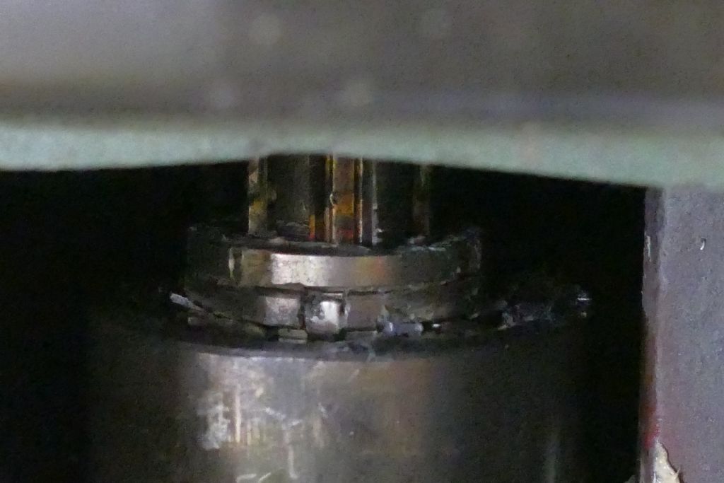
                                                The first thing to do is check the spindle bearings are properly adjusted. Take the front trim off and you should see a tab washer and two slotted nuts. Bend back the locking tab and loosen the top nut. Then tighten the lower nut, tighten down the lock nut and bend a tab back into a slot on the nut. The bearings should be tight enough to get warm when running but not too hot to touch. I'll post a photo shortly.

                                                This shows a slot with the tab bent up into it. Loosen the top nut, bend the tab down, loosen then retighten the lower nut (there should be an obvious increase in the force needed to tighten the nut when you get metal to metal contact in the bearings). Rotate the spindle by hand to check everything feel ok. Bend a tab up into a slot (not necessarily the same tab or the same slot) then tighten down the top nut. Run the machine at high revs for a while ( 10 minutes for example) and check the bearings are warm but not hot.

                                                Martin C


                                                p1160272.jpg

                                                Edited By Martin Connelly on 24/03/2022 09:40:58

                                                Edited By Martin Connelly on 24/03/2022 09:42:12

                                                #591383
                                                Hopper
                                                Participant
                                                  @hopper

                                                  Chris, thanks for posting the diagram. That makes the problem clearer now. But the solution could be more tricky!

                                                  It seems strange, as you know, that the quill can move downwards but the spindle does not.

                                                  I think Martin is right in the above post, the first think to check would be the spindle bearings. The spindle bearings should be holding both quill and spindle solidly so they move up and down together with no variation. The only movement should be the rotation of the spindle, not up and down movement.

                                                  It may be that if there is slack in the end float of the bearings, that the spindle is held in place by where it passes through the splines in the pulley at the top end that drives the spindle. Depending on how your mill works. I am not familiar with your model machine. But if there is slack in the bearings and the spindle is a tightish fit in the splined pulley that drives it, it could be possible the quill moves a small amount but the spindle does not.

                                                  #591387
                                                  Chris Mate
                                                  Participant
                                                    @chrismate31303

                                                    Ok, I took a test cut Aliminium bar:

                                                    A-I Trusted in Mitutoyo Dial Indicator(Red in drawing) mounted to head, measuring the Quil up/down with the Fine Adjust wormgear.

                                                    B-From an in dept experiment between the two guages setup, I determend that if I got them syncroed, then chose a target measure lower it to that, the Red Guage of course not on target with Blue gauge.
                                                    -Now if I pump the quil lock lever between lock and unlock, I can step by step advance the Red Guage to the same value as the Blue guage that dont change with the Quil Lock/unlocking.
                                                    -So from this I trusted that by using the pumping action I can mill ok.

                                                    C-I remove the Blue indicator, and put the aliiminium bar in the vice & tighten/Hammer down, tighten.

                                                    D-I am now ready to chose mill a starting surface…I milled that once, back, twice, back, thrice..
                                                    —–I mark this setting as zero on Red Idicator(Mitutoyo).
                                                    —–I then move the quil up a bit, wind the X- Axis back and measure the starting diameter with Digital Calier.
                                                    The result is 39.66mm.

                                                    E-I am now ready to chose a cut= -0.066mm off.
                                                    -I carefully Lock the Quil-Pump, Unlock-Adjust, Lock-Pump, Unlock-Adjust, Lock-pump, Unlock-no adjust needed target reached.
                                                    -I carefully mil it Once, back, twice, back, Thrice, unlock adjust Quil up.

                                                    —Move X-axis way back so I can measure(Vice in centre)…

                                                    Result:
                                                    Start=39.66mm
                                                    Target=39.594mm (-0.66mm)

                                                    Measured=39.57mm………..(The 0.066, the last 6 I guessed.(Indicator-.01mm).

                                                    I think I am happy, let me know…My problem is the effort to get to that, this effort seems impractical and wrong to me.

                                                    Edited By Chris Mate on 24/03/2022 10:57:45

                                                    Edited By Chris Mate on 24/03/2022 10:58:45

                                                    Edited By Chris Mate on 24/03/2022 10:59:46

                                                    #591393
                                                    Neil Lickfold
                                                    Participant
                                                      @neillickfold44316

                                                      I am having the same problem with an HM50 mill from Hare and Forbes or Machinery house.. The clearance between the cast housing bore and the diameter of the spindle cartridge assembly. Its not too hard to remove the spindle. In my one, there is about 0.05 mm to 0.06mm between the housing and the casting. It should be less than 0.01mm. I have taking apart my assembly and getting a company to hard chrome the outside with a build up of 0.05mm. I will lap it if needed to clean it up and will then make a lap for the casting bores if needed to be loosened off any. It looks like there is no wear on the spindle body and none to be seen or measured on the main castings. It seems that this is a very common problem with cheaper mills. A bridgeport mill spindle is made with around 5um of clearance and are matched fit assemblies. In my spindle there was casting sand and fine cast iron powder in there wearing out the bottom bearing. In mine is a taper roller bearing. Some have a sealed ball bearing. To check out my theory, I spray painted the outside and re assembled the spindle sleeve. At it lowest point it only had 0.02mm of movement. Before taking it apart , it had 0.12mm of movement. So flash chrome it will be. I am also going to check the concentricity of the bearing housings to outer housing before it goes for plating.

                                                      If they are not right I will have to think of the plan to correct them.

                                                    Viewing 25 posts - 1 through 25 (of 47 total)
                                                    • Please log in to reply to this topic. Registering is free and easy using the links on the menu at the top of this page.

                                                    Advert

                                                    Latest Replies

                                                    Home Forums Beginners questions Topics

                                                    Viewing 25 topics - 1 through 25 (of 25 total)
                                                    Viewing 25 topics - 1 through 25 (of 25 total)

                                                    View full reply list.

                                                    Advert

                                                    Newsletter Sign-up