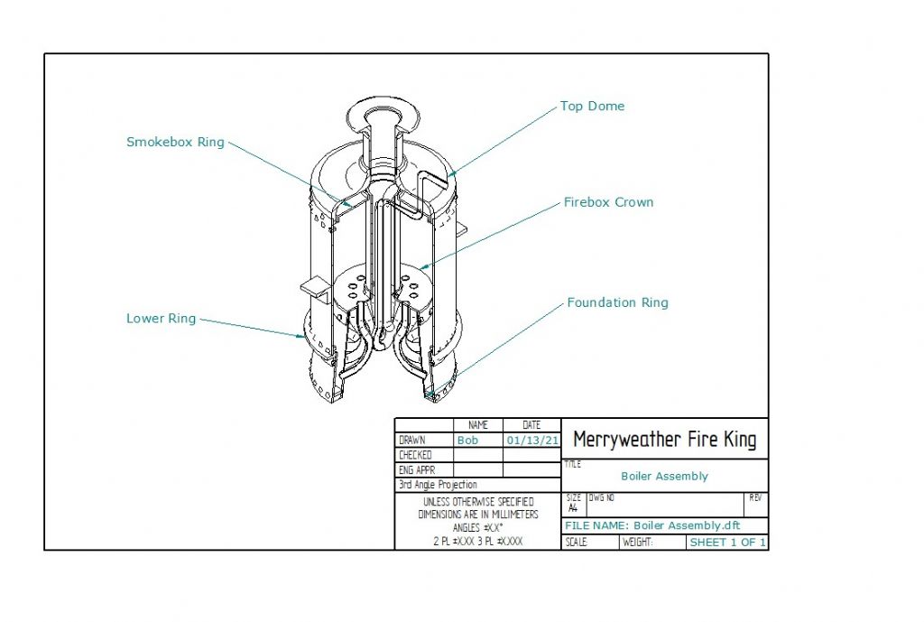
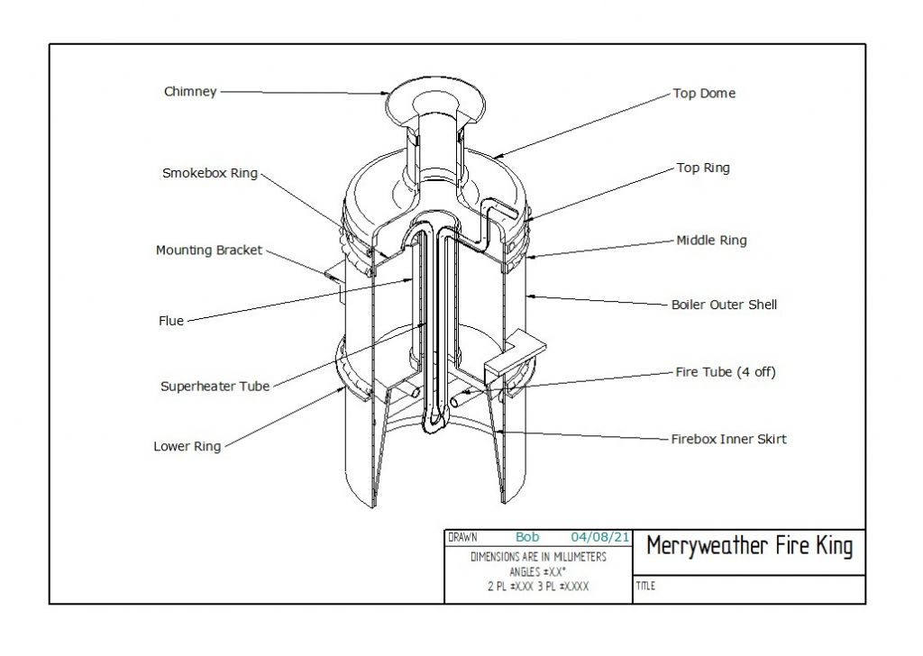
For a start I would not make as complicated as that – for one thing you don't need those water-tubes in the firebox on a model. Nor do you need copy the original, bolted-together design (which I think is hidden under the cladding anyway.)
For the next I would strongly advise, if you have not already done this, buying books on miniature boiler-making and silver-soldering. have a look in the Tee Publishing lists, particularly the Workshop Practice series. They tend to concentrate on locomotive-type boilers but the fabrication methods are all much the same.
Then (we've not even gone into the workshop yet  )…
)…
That drawing looks as if copied from a diagram of the original, which was designed for very rapid steam-raising to suit its purpose. Simply scaling full-size boilers in detail to small model size rarely works well, so some compromises are necessary for assembly methods and indeed actually making steam. So, prepare new drawings of the boiler in miniature, to normal model-engineering boiler practice, but fairly representing the original externally. Take especial note of dimensions, for a matter I will come to…
'
Why do you need those rings? Copying the full-size, with the 2-part boiler shell bolted together? That complicates things, but anyway, if you are going to build the fire-engine around the boiler, they would be hidden by the lagging.
If you do still want them, you are best making them as dummies to represent the prototype, but having no contact with the inside of the boiler. You would have to cut them from plate, and flange them by the normal methods in making miniature copper boilers. They could be soldered to the shell with a fairly-high melting-point soft solder, since they are not doing anything structural. Don't use through-fastenings to the shell, for them.
The rings were riveted on the originals, yes, but these were steel shells whose riveted joints were fullered and caulked steam-tight. Rivets are used in model boilers normally either as stays or as assembly-aids, and in both cases are silver-soldered along with the main jointing anyway.
If you fit those dummy bolting-flanges you could use brass sheet; but do not use brass on the internal surfaces of a boiler where it is exposed to high-temperature water and steam, as it is likely to decompose (the zinc dissolves out of the alloy, I don't claim to know the chemistry).
'
That firebox is probably more easily cylindrical with little or no effect on performance; but it will need to be of fairly thick wall because a cylinder (and presumably, truncated cone) is much weaker under external than internal pressure.
A reasonably deep crown-plate flange inside the firebox shell will add to the hoop-strength; that central flue, fitted in an outwards-flange in the crown-plate, will act as a longitudinal stay.
You might find copper tube of appropriate diameter for it and indeed for the shell, with some compromises on scale to suit what is available. Otherwise it's rolled shell and lap-plated, silver-soldered joint. Though if you want you could roll it the firebox conical without much more difficulty – after all, some locomotive boiler have tapered boiler barrels often copied in miniature.
'
That pipe inside the flue is a super-heater. In full-size they had room to form it like that, but in a model you would almost certainly have to make a return-bend to join two lengths of pipe. The usual, in model locomotives, is a "spear-point" of or bronze, with two holes at converging angles to take the ends of the tubes; held in with high-melting-point silver-solder.
'
Order of assembly: the firebox and flue unit, assemble that into the outer shell which has already had its various bushes or mounting-pads for the fittings, then the foundation-ring and top tube (or flue) -plate.
Note that " then the foundation… " .
Because…
The fly in the cutting-fluid here, is the major detail you have not shown: the fire-hole. I know the, Merryweather boiler because a friend used one for a freelance narrow-gauge loco, and on that example and as far as I know all Merryweather boilers, the firehole is in the side. So it has to pass through the water-space round the firebox.
I must admit I had to think hard, but this is how I see it:
The fire-hole is a short tube of length is the width of the water-wall at the chord formed where it penetrates the wall, plus the sum of the two plate thicknesses. You would have to draw it out, because all its circumference has to penetrate fully, both walls.
However, it also constrained by the assembly; hence my point above, about drawings.
Size the innards so when the fire-hole tube has been soldered into the firebox, that assembly, with the flue, will slide into the boiler barrel with the foundation-ring not yet fitted.
Move it across the shell so the firehole tube can poke through its hole in the shell.
Then fit the foundation-ring and top-plate, ensure all aligned correctly, and silver-solder them together.
'
You don't really say how big this is, but you will need different melting-point silver-solders for the different parts, and you will need put a lot of heat into the metal as rapidly as possible.
Everything needs drawing first, dimensioned carefully, so that it can be fitted together.
'
Or just run the model on air… I think fully-working Merryweather steam fire-engines have been made, so it's feasible. You need translate full-size boiler-making to its model-engineering version.
Bob Wild.


 )…
)… 


