A full set of drawings for Norden can be downloaded HERE.
What follows is the slightly edited text from the introductory article.
Norden, A Nineteenth Century Mill Engine to 1:12 Scale
One of the attractions of model engineering is the opportunity to makes a model of unusual prototypes, perhaps something that no-one has tackled before. Supreme examples of this could be the gold-medal recreations of strange Victorian steam vehicles that grace the exhibitions. Some of these were never constructed in full size, despite the hopes of their patent holders! But this does not mean you have to be an elite modeller to enjoy the satisfaction of creating a distinctive model. There are hundreds of small stationary engines to be tracked down, in old engravings, in photographs, in museums and even on scrapheaps. Google Books is a particularly rewarding source of engravings of old steam engines and mechanical devices. Some old engravings have almost every detail in them, but it is possible to make a feasible reconstruction of a model from even the most basic of information. There is no magic formula required, just model engineer’s ingenuity and perhaps an ability to ‘think in scale’. I would like to recount the story of how I went about recreating a ‘lost’ steam engine. It all started several years ago when, reading some yellowing post-war issues of Model Engineer, I came across the following letter from 1947[i]:
Enjoy more Model Engineer reading in the monthly magazine.
Click here to subscribe & save.
|
DEAR SIR,— In the ruins of an old mill at Norden, near Rochdale, there is an old steam engine which has been left rotting away with five others, and a Lancashire Boiler. The bed of this engine was like a table, cast with the top and legs in one piece and bolted down to a cast iron bedplate, which in turn is bolted to a slab of concrete. The height of the table is 4 ft. 6 in., and the top of the table measures 2 ft. 4 1/2 in. by 1 ft. 5 1/2 in. The flywheel is 4 ft. 3 in. diameter by 5 in. face. There are six curved spokes of + section. The cylinder is bolted direct to the bedplate by its bottom flange. The bore is approximately 9 in. and the stroke is 13 in. The crosshead is of the alligator-type and runs between locomotive-type slide bars, which are 2 ft. 3 1/2 in. long by 2 1/4 in. wide. The connecting rod is bellied and has strap and cotter big- and little-ends. The centres of the connecting rod are 2 ft. 1 in. The crankshaft is 2 1/2 in. diameter and rests in two bearings, one at each end of the table ; the single crank web is balanced. The governor has two 5 in. diameter balls and was driven direct off the crankshaft by bevel gears to the tops of the governor spindle. I have no idea of the age, origin, speed or working pressure of this engine, but probably some reader could throw some light on the matter. Yours faithfully, Shaw, Lancs. S. Lees. |
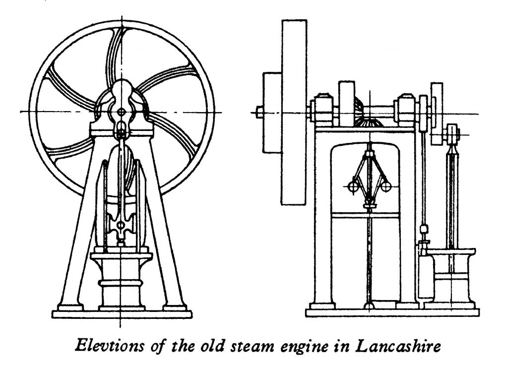
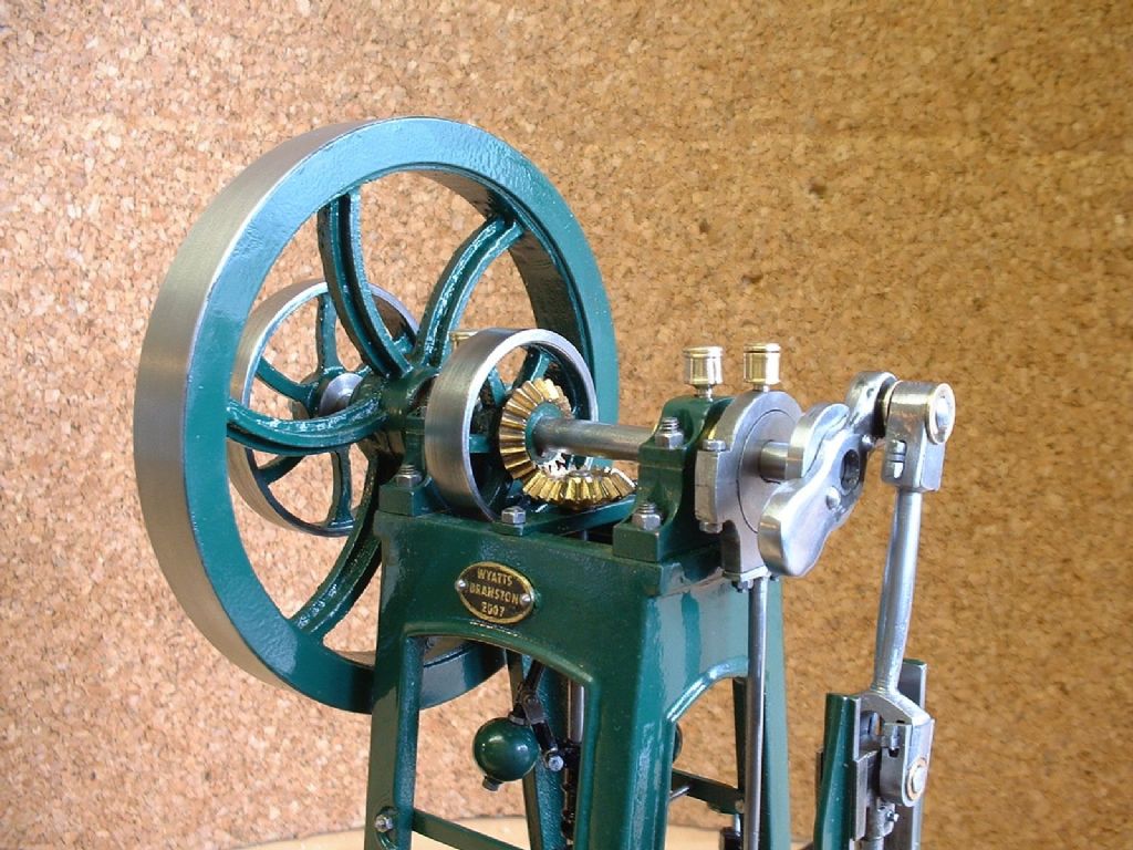
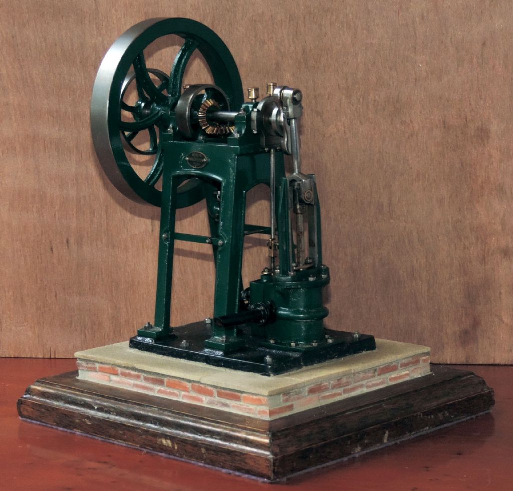
A tiny sketch, reproduced here larger than original size accompanied the letter. I had been considering making a scale model of an ‘interesting’ prototype for some time. Despite its apparent simplicity, the sketched engine was characterful and immediately appealing – it is clear why it attracted Mr Lees notice. The ‘bed like a table’, distinctive flywheel and the arrangement of cylinder and slide bars all looked like presenting worthwhile challenges. None of these challenges was too difficult to overcome, and the end result was an unusual and rewarding model (Photos 1,2).
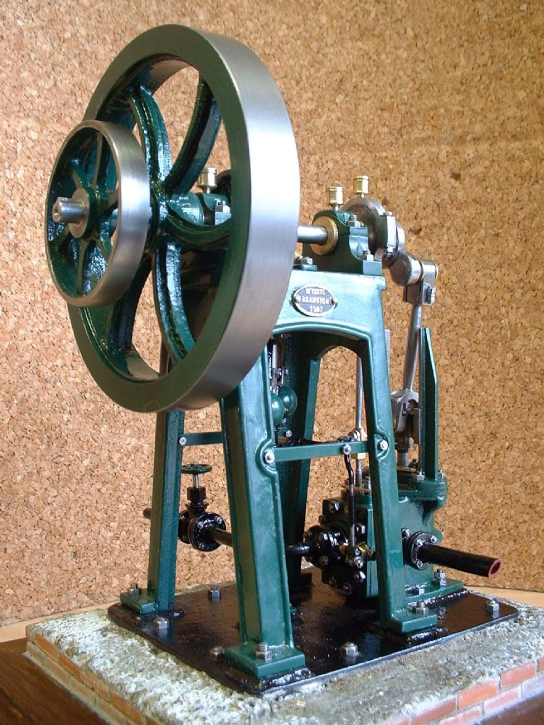
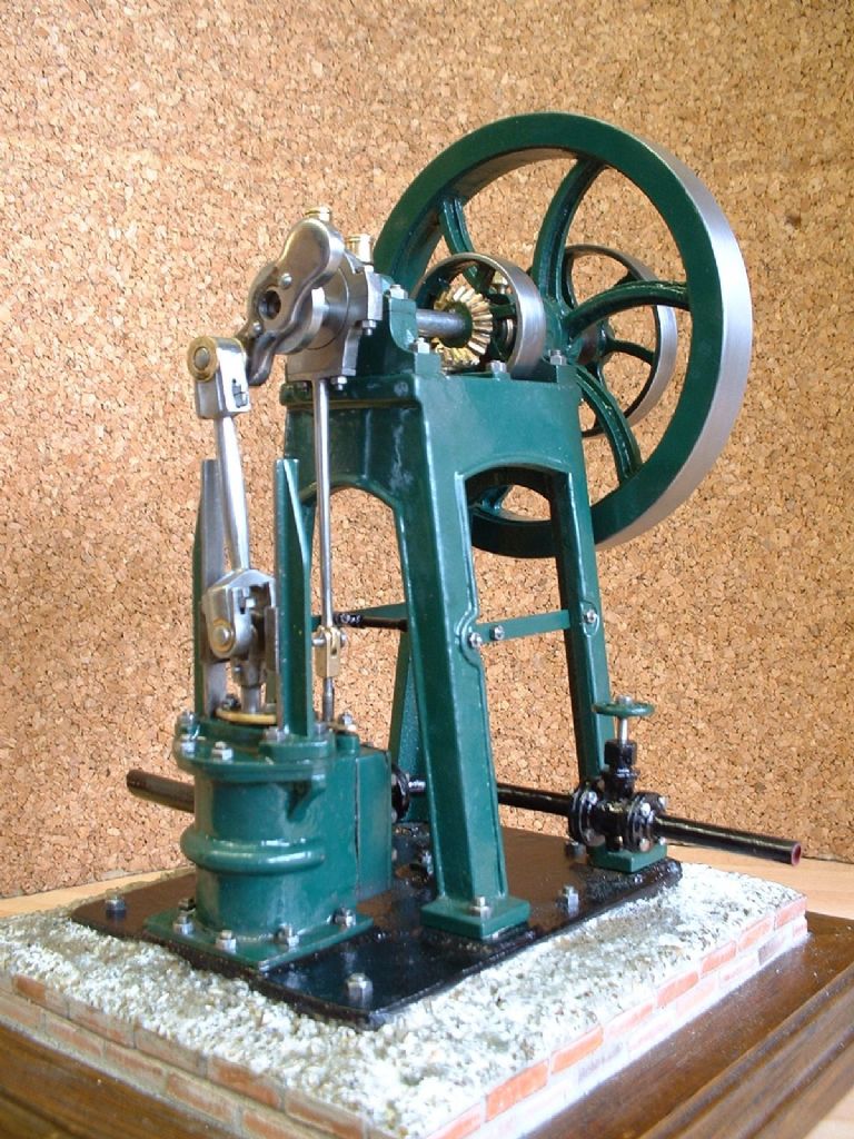
The model is based solely on Mr Lees drawing and description. In all cases I followed the dimensions in the letter exactly. Except where the sketch is obviously simplified, I followed it as closely as is practicable. I don’t claim perfection, and there are a few areas where constructors might improve on my interpretation.
One of my first tasks was to see just what information I really had about the engine. What did Mr Lees letter and drawing tell me? What could be extrapolated from them? Finally, what was left out? It was quite surprising how much information can be gleaned from these sparse sources. The engine is from an old mill at Norden near Rochdale. The only similar engines I found picture of were small colliery winding engines, but this is not a colliery engine. A mill engine would not have been reversible, and would need to run at a controlled speed, consistent with both the governor and lack of reversing gear. The drawing indicates two pulleys that would have allowed the engine to drive line shafting in the mill. It was ‘old’ in the 1940s, by which time the mill itself had fallen into ruin. The design seems typical of the mid-late1800s to my relatively untrained eye. It was one of six, possibly not the same as any of the others, and probably the most remarkable (else why pick this one to report on?). There was one Lancashire boiler; presumably powering several if not all of the engines. I like to think that this old-fashioned engine was an early experiment in steam power by the mill that found a niche alongside later, larger and more powerful engines. Perhaps it was a useful standby, a source of auxiliary power or maybe it ran some small process or activity over a long and useful life?
The letter and sketch conflict in just two places – the dimensions of the governor balls and the face of the flywheel are not drawn to the specified dimensions. In both cases I followed the letter. The most obvious effect of this is that the governor balls on the model look a lot larger than those drawn in the sketch. Three-inch balls as per the sketch might be rather small for a Watt Governor – another engine of similar date that I have an accurate engraving of appears to have 4” balls. This suggested to me that the drawing was probably made to the main dimensions, perhaps guided by some quick sketches, then finished from memory. When scaling from the drawing, I assumed that sizes are approximate, and assumed the full size would generally be built more or less to inches or significant fractions of an inch. As well as information of which I could be confident, there was a lot I could work out by extrapolation. Unlike Donald Rumsfeld, I chose not to lose sleep worrying about the unknown unknowns. It is clear that the relative proportions of the various parts of any stationary steam engine do not vary greatly, so a policy of copying parts from similar-sized engines is unlikely to result in disproportionate results. As far as I have been able, for all (known) unknown details I have tried to follow my understanding of nineteenth century practice. The one notable (but hidden) exception has been using o-rings instead of loose packing for the glands and piston.
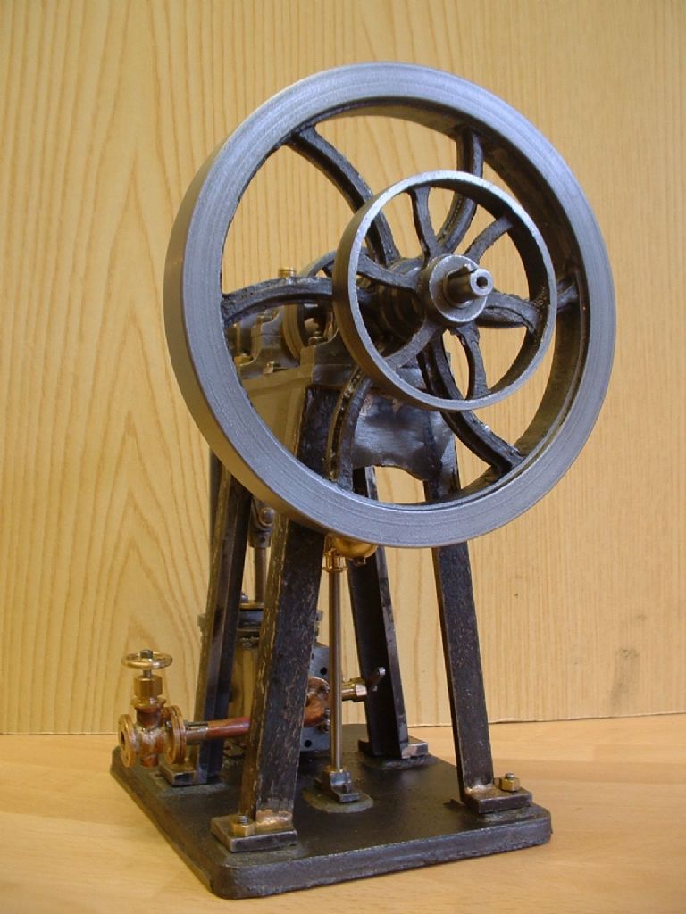
A few years after completing the engine, I discovered the existence of some a-frame engines by John Chadwick. These bear such a strong family resemblance the original may have been a Chadwick engine, although I think the Norden engine is rather older, and Mr Lees did not record the maker’s name cast into the frame. There are differences in the Chadwick engine from with both my model and Mr Lees’ drawing – be these errors or just because it is a different model. But it confirms one thing – the large size of the governor balls is appropriate!
I decided early on to work to a scale of 1:12. This would be well within the capacity of my equipment, whilst keeping calculations simple. It would produce a model of reasonably compact proportions whilst being large enough for scale sized fixings to be used (Fig. 1). The flywheel is 4 1/4” diameter, so even a 2 1/2” centre height lathe could be used to make this model. Working drawings were prepared using Corel Draw, mainly to check clearances and to ‘share out’ available space between different components. I did not produce fully dimensioned or detailed drawings, so the drawings accompanying this series have been drawn from the model. I have a personal preference for imperial dimensions for models of ‘imperial’ originals, so almost all measurement was in inches (which seem to be doing just as well in the real world as they were when ME writers were predicting their imminent extinction over a quarter century ago). This is why the drawings are dimensioned in inches. I have given no indications of types of fit; model engineers don’t make parts to be interchangeable and have the wits to understand the difference needed between a shaft running in its bearing and a flywheel fixed on its shaft. Some dimensions will need to be checked as you go, especially to allow for variations in fabricating the table.
I produced my own patterns and had castings made for key components and tried to avoid buying in anything other than fixings. On the whole, I achieved my aim, which makes an unusual model of a unique engine. Although there were some interesting puzzles along the way I didn’t encounter any problems that would stop any model engineer from doing the same. Whilst I can’t promise anyone a gold medal, I am happy to assert that any reader of this magazine who has already built a simple steam engine, is capable of building the engine.
To summarise what I did myself: all of the castings (base, cylinder, pulleys, flywheel) are from my own patterns. The patterns for the flywheel and the two smaller pulleys were turned and milled from solid disks of aluminium alloy. The pattern for the base was fabricated from basswood (lime) and birch plywood. That for the cylinder comprised several materials, including wood, aluminium and acrylic sheet.
Some other details of the model are that castings were obtained for the steam chest and its cover and the cylinder top cover, but the patterns were undersized and the parts machined from the solid instead. I have since remade the patterns for these parts. The table is not a casting; a pattern was prepared, but rejected as too complex to cast at this scale.
For those wishing to build this model, I have lodged the patterns with longstanding supplier Blackgates Engineering[i], who can also supply full sets of drawings.
The governor spindle runs in brass bushes and operates a butterfly valve on the front of the steamchest. It works, but is not very effective – speed control is best left to careful adjustment of the steam stop valve. All the parts assembled to the crankshaft are held in place solely by cotters and wedges, and the piston rod bearings have three sets of wedges and cotters. I machined the bevel gears with my own cutter made using the methods described by Ivan Law. I used brass gears rather than cast iron ones, though brass were used on some prototypical gears of this size (9” diameter) cast iron would be more likely.
Aside from production of the patterns, the model took about five months of spare time to construct. The main machine tools used were a much-modified Clarke CL300M lathe, a pillar drill and an ARC X2 mill. My bandsaw also played its part.
The finished engine runs smoothly and very quietly on air at less than 1.4psi (Measured on a genuine and rather fine 19th century Compound Gauge by Bourdon of Paris, reading +/- 4psi) at a steady 70 rpm, and with care can be persuaded to run slower than this.
This is a detailed model and perhaps not ideal for an absolute beginner, so rather than describing every machining operation in detail, I will illustrate how I interpreted the relatively sparse information on Norden, and how I filled in the gaps. I will give guidance on the more difficult and unusual machining operations, including some lessons I learnt along the way. The remainder of this series can be access in the Model Engineer online archive.
Neil Wyatt
Postscript
I have since discovered, or been guided to, a small number of Chadwick engines., notably at the Northern Mill Engine Society and the Manchester Museum of Science and Industry. These engines all appear different to Mr Lee’s description of Norden, which may represent one of Chadwick’s earlier engines. All of these engines have three features not seen in Norden – the A-frame is bolted down inside the angle of the legs and the guide bars are braced to the A-frame, finally, the ‘alligator-crosshead’ is hollow and the connecting rod has a single eye, instead of a fork as I have modelled it. You may wish to incorporate these features in your model, as I suspect that this would have been the arrangement on the original prototype of Norden..
Post-Postscript
As a, hopefully, final note to this tale I was unsatisfied with the rough 'concrete' base. I modified this by levelling it and adding sandstone flags, which I think looks much better.
[i] Model Engineer Number 2403, Volume 96, p.726, 12 June 1947.


