Since getting the SIEG SX2.7 at the start of the Milling for Beginners series (starts MEW 261) I have found during use a few items that could be improved upon. Some of these are specific to the SX2.7 others could be applied to any machine.
Spindle Spanner.
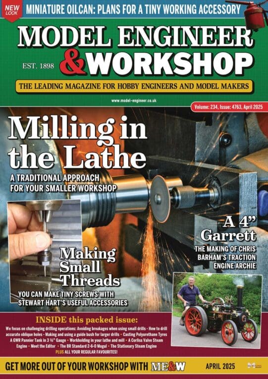
The supplied pin spanner that is used to hold the spindle while either tightening/loosening tooling or releasing/tightening the drawbar has tapered pins which I found tended to easily ramp out of the holes when being used.
My remedy for this was to file off the back of the pins where they had been peined over so that they were flush with the spanner body and then drive the pins out of the holes with a parallel punch. New pins with parallel sides can then be turned up from 5mm dia round bar, a chamfer put on the edge and their spigots sized to fit the holes in the spanner and about 1mm longer than the spanners thickness.
Push the pins into the holes and with the end of the pin resting on something solid use a ball pein hammer to lightly pein over the ends much like you would a rivit but just enough to hold them in place. Photo 18.
Spindle Spanner Hole Location
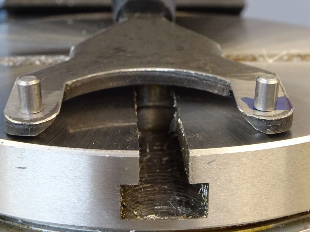
A related item is the need to either feel about to find the holes in the end of the spindle or bend down and look up to see where they are every time you want to use the spanner. I got over this by marking out their positions on the side of the spindle, if you use some masking tape and pencil there is no need scribe on the metal. I then used a spot drill in my cordless drill to form two conical recesses which were then filled with a bit of paint to make them easy to see. I can now offer up the spanner in approx the right location and it soon finds it’s way into the holes. Photo 19 & 20.
Draw Bar Auto Release
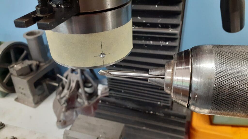
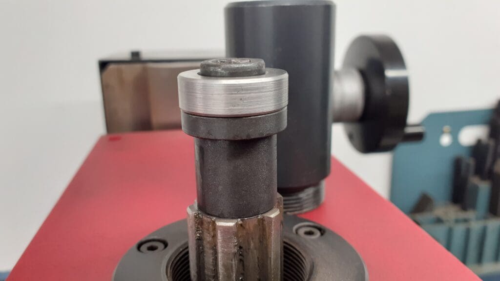
On the SX2.7 the hold of the R8 taper can be released by unwinding the drawbar until it contacts the black metal cap at the top of the head at which point resistance can be felt and turning the key a little more will “Pop” the tooling out of the taper.
I found that the point at which the taper released was very close to where the drawbar completely screwed out of the tooling’s thread. This not only risks the tooling dropping as it is released but all the force is being taken by less than one turn of thread as very little is engaged.
My remedy for this was to turn up a simple spacer ring, the OD to match that of the drawbar’s flange and the OD to be a close but sliding fit on the hex socket head above the drawbar’s flange and 8mm long. Photo 21. A drawing for this can be found under the “Workshop” heading on the ME Website. With the ring in place the drawbar will release the taper after approx three turns of the hex key.
Enjoy more Model Engineer reading in the monthly magazine.
Click here to subscribe & save.
X-Axis hand wheel Spring
As a safety feature the X-Axis hand wheel comes fitted with a spring to keep the dog clutch drive disengaged which is really only needed if using power feed where the handle can fly round at a fair speed and could give you a knock. Having to push against this spring when feeding or putting on a cut makes it hard to feel how much effort is being put into moving the work against the cutter or to just sneak up on a cut or when touching off against an edge.
Luckily the spring is easily removed which makes use of the hand wheel a lot more comfortable and the spring can be put somewhere safe until you get round to thinking of refitting it when a power feed is added to the mill.
Extending Power Feed Stops
The SX2.7 that I have is one of the earlier models where the tee slot in the front of the table stops about 50mm in from the ends rather than the newer ones where it runs full length. Therefore when I fitted the limit stops for the SIEG power feed unit I lost about 50mm of possible X axis Travel as the stops could not be mounted at the points where the table runs out of travel and caused it to stop short.
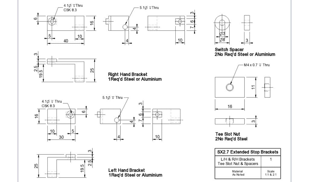
Fig 1. shows the parts that I made to regain the full length of travel which are basically handed “L” shaped replacements for the supplied straight stop brackets, new tee nuts and a pair of spacers to move the switch box out allowing the leg of the new L bracket to pass behind. The existing stop screws, springs and nuts are reused.
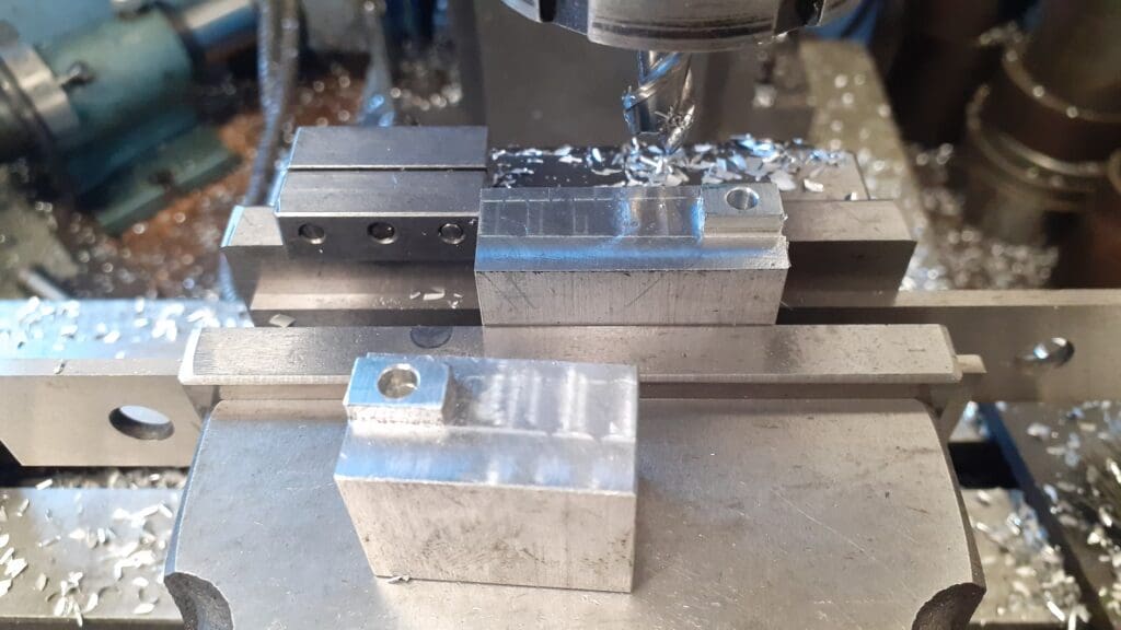
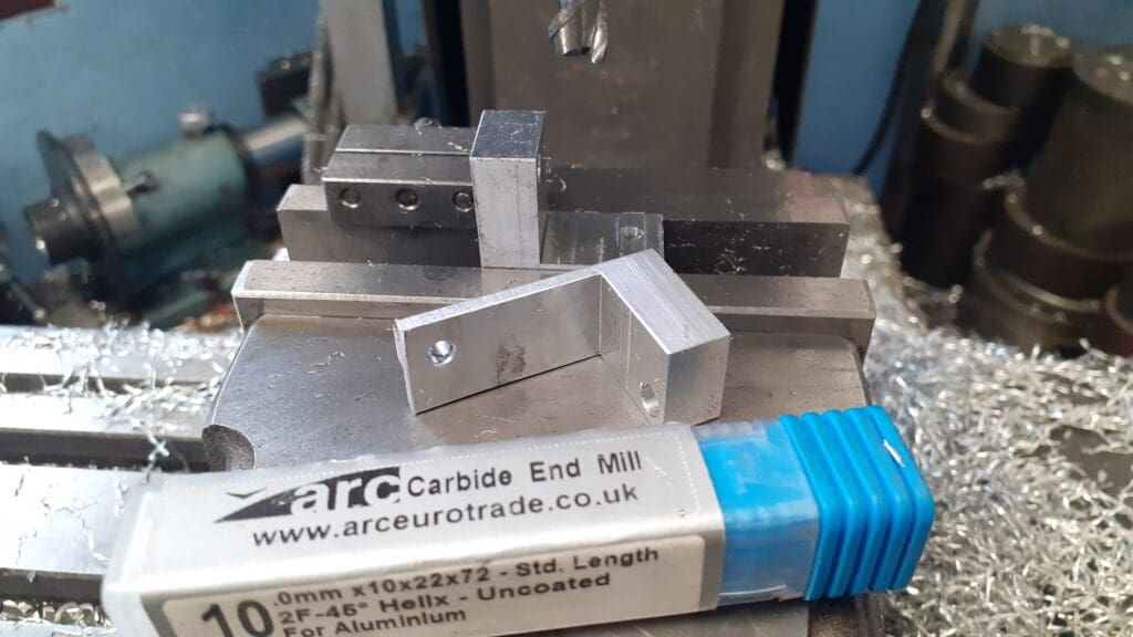
Start by milling two rectangular blocks to the respective overall sizes, I used 6082 aluminium but mild steel could also be used. It is worth roughly marking the positions of the holes and milled features as the opposite handing of the parts can get a bit confusing. Then drill the various holes, I made use of a vice stop to save having to locate the holes more times than needed. Photo 22.
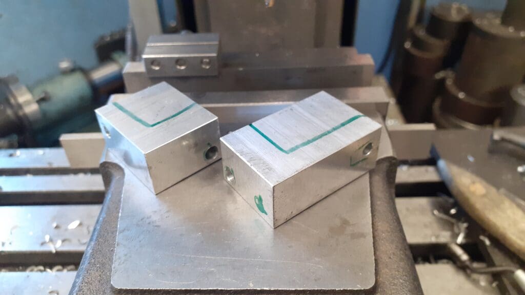
The small raised area that fits into the tee slot can be milled next, touch the end of the tool off on the top of the block, move clear and lower 3mm then lock the height and all the cuts can then be done at the one height setting. Photo 23.
Turning the blocks the opposite way up in the vice the remaining material can be milled away to form the “L” shape. As it was aluminium I used one of the cutters designed for non ferrous and aluminium and took full depth passes of 19.5mm stepping over 1mm per pass that gets the job done quite quickly and makes use of all the flutes that you have paid for rather than just wearing them towards the end. Photo 24.
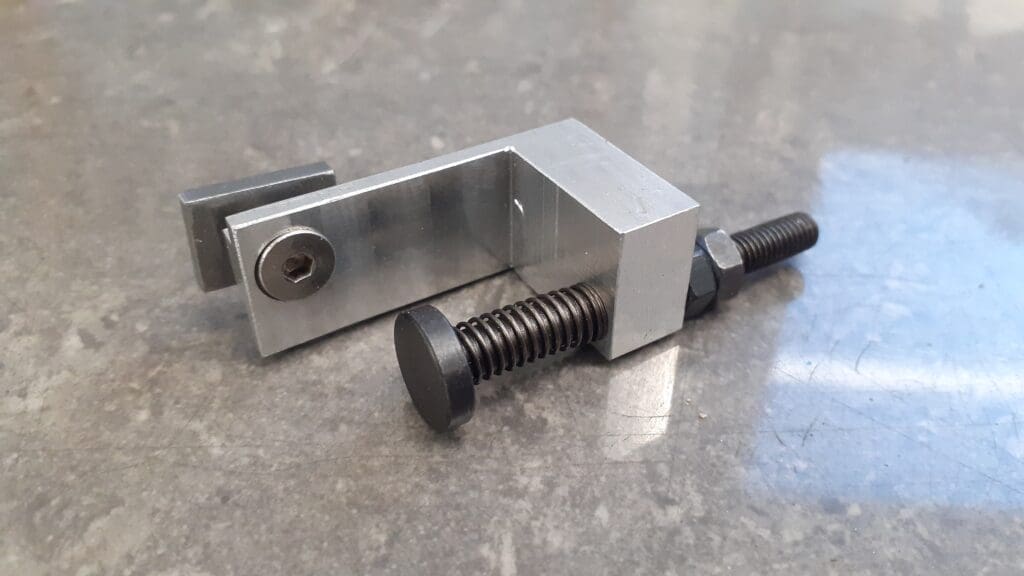
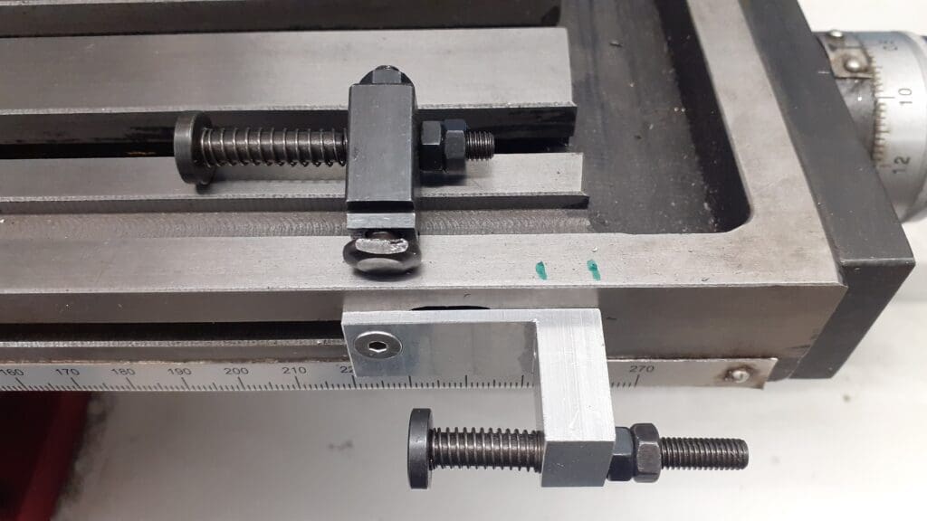
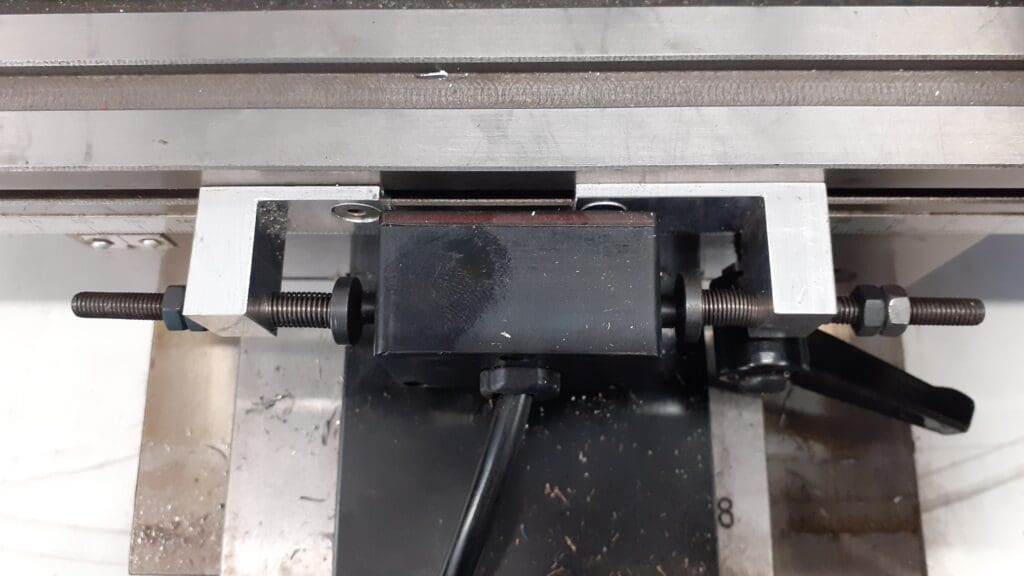
The last job is to countersinking the M4 clearance hole and ease all the external corners with a file. The Tee nuts and spacer rings are simple parts that should not really need any explanation. Photo 25 shows the assembled right hand bracket. Photo 26 shows the original bracket laid where it would have fitted to show the extra travel that the new bracket has gained, approx 30mm on the right and 20mm on the left hand one. Lastly Photo 27 illustrates how the spacers allow the new brackets to pass behind the power feed’s switch box.
https://www.arceurotrade.co.uk/Catalogue/Machines-Accessories/Milling-Machines/SIEG-SX27-Mill