Introduction
As I mentioned in the previous article some posts on Model Engineer Forum prompted me to do
some test cuts and confirm if what I have been advocating was the best approach to using insert
shell and face milling cutters with bench top hobby mills.
The Problems.
Enjoy more Model Engineer reading in the monthly magazine.
Click here to subscribe & save.
The traditional approach has generally been to run at a moderate speed and take depth of cuts and
chip loads that have always been within the capacity of the more substantial ex industrial or large
imported machines which typically have belt or gear speed reduction and a solidly built. However
when it comes to using these cutters on bench top hobby machines there are several factors that
come into play and make the traditional approach not ideal.
Firstly is the overall rigidity of the smaller hobby machines which is less than a big floor standing
machine so there is a tendency for the tool to get pushed away from the work if the cut puts too
much force into the structure. Not only can this reduce the quality of the finished surface but it will put an increased load on the motor, higher current through the control board and additional loads having to be transmitted by the gears which can be more of an issue on machines fitted with nylon gears.
Secondly machines with electronic variable speed will not be delivering there full potential at the
lower end of their speed range which runs the risk of stalling the machine with the inherent effect on motors and control boards, gears and belts. Machines with toothed belts could damage the belt
where as a traditional machine is more likely to have simple vee belts that will just slip if the load is
too much.
Thirdly the type of insert used can make a lot of difference to how a hobby machine performs with
these type of cutters. As with lathe tools the usually supplied and used inserts are moulded and the actual cutting edges are not that sharp so a substantial machine is needed to drive the inserts into the metal.
Jargon Explained
Before looking at how to overcome the points above some explanation of the terms that are used
may be useful
Cutting Speed. The cutting speed for any material is given as meters per minute (m/min) or feet per minute in imperial and is the speed that the cutting edge moves though the material, this can also be shown as Vc (Velocity of cutter) The cutting speeds shown in various makers and suppliers catalogues or websites tend to cover a range of speeds for any given material and can also be different depending on the type of cut being taken.
Spindle Speed. Not to be confused with cutting speed this is the actual revs per minute that the mill spindle is rotating at and should be calculated to suite the material being cut and diameter of thecutter being used.
For example if the cutting speed for your particular application is given as 80-120m/min take the
average of 100m/min as a starting point. Say you are using a 50mm dia cutter then the calculation
for spindle speed is:
Vc / Cutter Circumference in meters = 100 / ( 0.050 x 3.142) = 100 / 0.157 = 637rpm
Chip Load. This is the thickness of cut that each individual insert will remove per revolution as the
cutter is advanced into the work given in decimals of millimetres or inches. It is generally taken at a
point inline with the spindle axis. It is often shown on charts and tables as Fz (Feed per Tooth) but
can also be shown as tz ( thickness per tooth). As with the cutting speeds chip loads tend to be given over a range which will depend on the material and type of cut.
Feed Rate. This is the rate at which the work is fed into the rotating tool and requires another
calculation using the Spindle Speed, Chip load and number of inserts or flutes to arrive at the rate to use . It is usually given as mm per minute or inches per foot in imperial. So if we take the 637rpm from the 50mm dia cutter above as 5 insert shell Mill and a chip load of 0.1mm per tooth the calculation is:
Spindle speed x Number of inserts x Chip Load in millimetres 637 x 5 x 0.1 = 319mm/min Feed.
Depth of Cut or “DOC“. This is usually thought of as the amount the cutter is lowered per pass so
the axial amount of fed, given in millimetres or inches and sometimes shown as Ap. With a common 1604 size insert this can range from 1mm to 14mm on a typical industrial chart but that is going to be very unlikely on a hobby machine.
Cutter Engagement. This is how much of the diameter of the cutter is being used, and can be
thought of as the sideways version of DOC. Given in mm or inches and sometimes shown as Ae.
Typically for facing larger work you may use 2/3rds of the diameter so for a 50mm dia cutter you
would use in the region of 33mm cutter engagement, which can also be referred to as stepover.
A different Approach
Starting to look at the points mentioned earlier the first is the rigidity of the machine. There is not
much that can be done about this except to ensure any non moving axis are locked and that quill
extension is kept to a minimum. However by reducing the cutting loads there will be less reaction
force from the cutter trying to deflect it away from the work piece, these loads can be reduced in a
number of ways.
-Reduce the chip load to as low as possible but not so far that the inserts are rubbing rather than cutting so something like 0.02mm would be a good starting figure
-Reduce the depth of cut to something around 0.5mm, this is approx 2/3rds of a typical inserts
0.8mm corner radius and helps to thin the chip.
It is possible to do something about speed and that is to wind the knob up. By using the highest of
the speed ranges give that can be anything up to 300m/min for steel and maybe even a little more it is possible to get the machine running at its maximum spindle speed where it will be delivering all it can. As the cutting speed affects the feed rate then running at these higher speeds allows a faster feed rate which goes a long way to compensate for the reduced depth of cut for example two passes of 0.5mm deep with a feed rate of 300mm/m does not really take any longer than one pass of 1mm deep at 150mm/min.
Inserts are another area that we have some control over so by using the ground and polished ones
that are intended for Aluminium and other non ferrous metals on everything including steel, cast iron and stainless steel the cutting forces required can be reduced. These inserts may wear a little faster when used on these other metals but overall cost is not so great particularly compared with the possibility of replacing a cooked motor or control board. For the budget conscious use the inserts for Aluminium and nonferrous as intended and when the edge starts to go off switch to using them on steel as they will still be sharper than the pressed type. It’s a similar approach to using new files on brass to start with.
Putting it into practice.
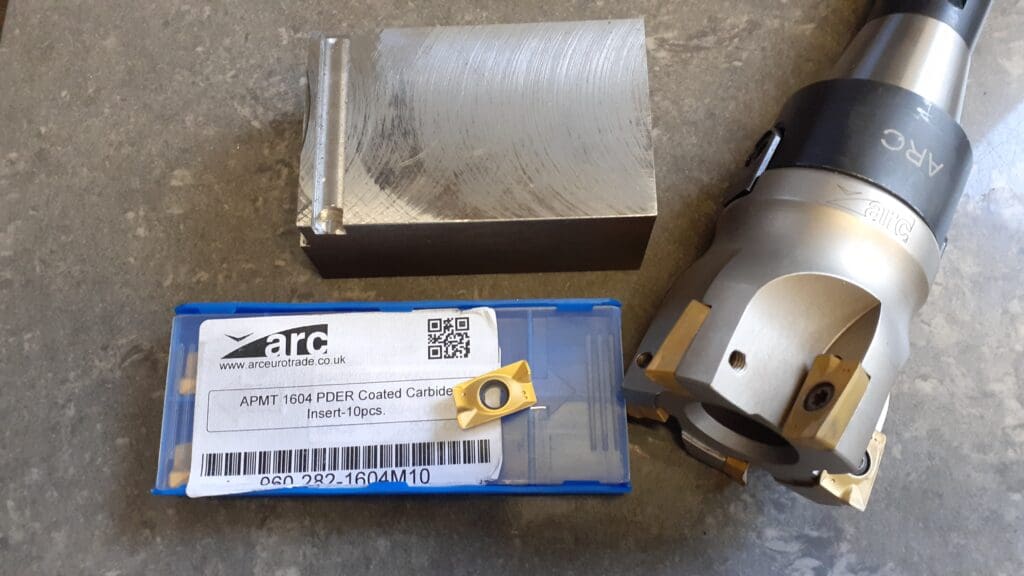
For the test cuts I used a piece of 40mm wide 070M20 (EN3) steel which gave almost 80%
engagement of the 50mm dia 5 insert cutter from ARC Euro Trade. I then used the power feed on
the SX2.7 to take various cuts at 0.5mm deep firstly using the moulded APMT inserts. Then a final
cut at 48mm wide which is near enough 100% engagement when corner radius of the inserts is
taken into account I have compiled these cuts on a video as that gives a better indication of the rates of cut being taken than just showing a photo of a machined piece of steel after each cut. It also gives an audible indication of how the machine is being loaded and should be born in mind to be compared later with the APKT inserts.
The parameters for each cut are shown on the video starting at a modest 1200rpm and chip load of
0.015mm giving a feed rate of 90mm/min right upto 2000rpm and chip load of 0.045mm giving a
feed rate of 450mm/min. Photo 8. Shows the resulting finish and the cutter used.
Although the machine did handle the very fastest of the feeds I could hear it was straining and the
finish was not ideal so for these type of inserts I would suggest a chip load of 0.03mm as about the
maximum when using the full width which equates to a feed rate of 300mm/min going upto 0.04mm when doing overlapping cuts so that is 400mm/min with 33mm engagement(stepover). Both with 0.5mm DOC.
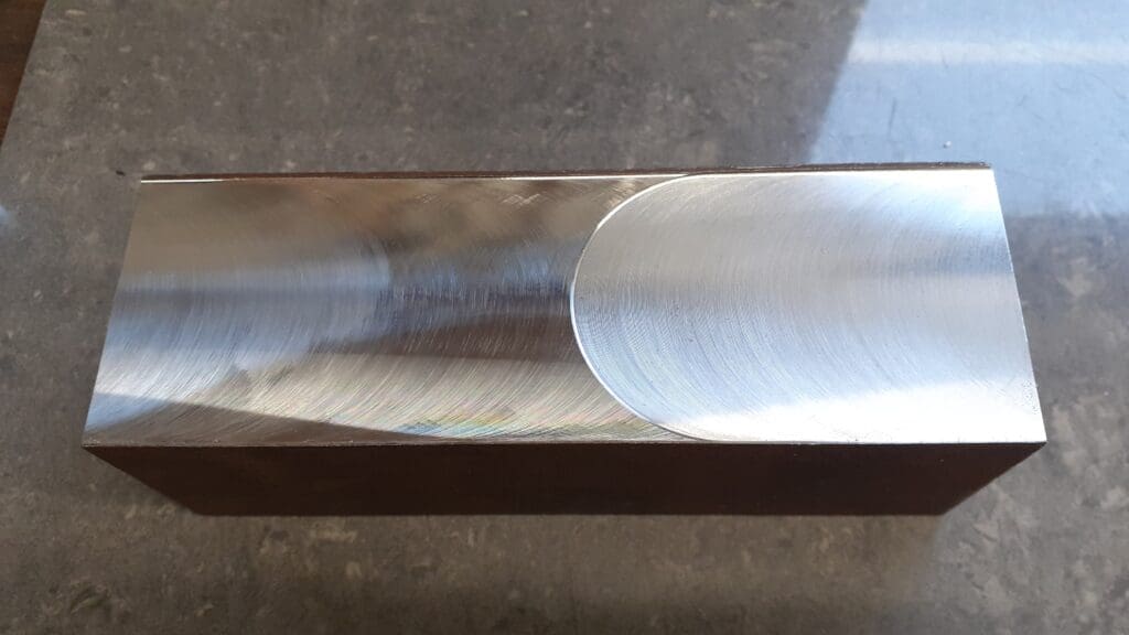
Next time I will look at the improvements changing from the finish obtained using APMT inserts
shown on the left of Photo 9 to the better finish on the right using APKT inserts can make.If You can’t wait for Part 2 to be posted here get a copy of MEW 341 which is due to be published in the next few days.
Mill and Cutters supplied by and available from ARC Eurotrade
https://www.arceurotrade.co.uk/Catalogue/Machines-Accessories/Milling-Machines/SIEG-SX27-Mill
https://www.arceurotrade.co.uk/Catalogue/Cutting-Tools/Indexable-Carbide-Shell-Mills